Salus ST620VBC User manual

Instruction Manual
Model No ST620VBC
Programmable Thermostat with Plug in RF Boiler Control
2
Salus ST620VBC Manual 008_89 09/02/2012 14:00 Page 1

ST620VBC INSTRUCTION MANUAL2
Salus ST620VBC Manual 008_89 09/02/2012 14:00 Page 2

PRODUCT COMPLIANCE
This product complies with the essential requirements of the following EC Directives:
•Electro-Magnetic Compatibility directive 2004/108/EC
•EC Marking directive 93/68/EEC
•R&TTE Directives 99/5/EC
SAFETY INFORMATION
These instructions are applicable to the Salus Controls model stated on the front cover of this manual only,
and must not be used with any other make or model.
These instructions are intended to apply in the United Kingdom only, and should be followed along with
any other statutory obligations.
This accessory must be fitted by a Competent person, and installation must comply with the guidance
provided in the current editions of BS7671 (IEE Wiring Regulations) and Part ‘P’ of the Building Regulations.
Failure to comply with the requirements of these publications could lead to prosecution.
Always isolate the AC Mains supply before installing or removing the Integral
RF Boiler Control to the boiler.
When fitting or replacing the batteries, do not mix old and new batteries together.
Do not use rechargeable batteries.
Please leave these instructions with the end user where they should be kept in a safe place
for future reference.
3ST620VBC INSTRUCTION MANUAL
Salus ST620VBC Manual 008_89 09/02/2012 14:00 Page 3

INTRODUCTION
The ST620VBC comprises of the S series programmable room thermostat with an integral plug-
in RF boiler control. The RF boiler control is a direct replacement for the basic time clock or
blanking plate usually supplied with the boiler. Installing the RF boiler control takes minutes.
Once installed, you will benefit from all the control features of the Salus ST620 programmable
room thermostat.
Your new ST620VBC includes the following:
ST620 Programmable Room Thermostat
A programmable room thermostat is a device that combines the functions of both a room
thermostat and time controller into a single unit. The programmable thermostat is used to switch
your heating system on and off as required. It works by controlling the temperature according
to a series of programmed time settings that take effect at different times of the day.
The ST620 programmable room thermostat is a stylish and accurate 5/2 or 7 day programmable
electronic thermostat with a large, easy to read display. This programmable thermostat has been
specifically designed to be used with the integral RF boiler control.
Features
•Touch Ring Technology
•Large LCD with White Backlight
•Stylish Casing
•Intelligent Communication Technology
•Battery Powered with Replacement Indicator
•Frost Protection
•Burner on Symbol
•Radio Controlled Clock (RCC)
•Holiday Function
•Service Function
•Six Time / Temperature Settings
•Secure RF Transmission
ST620VBC INSTRUCTION MANUAL4
Salus ST620VBC Manual 008_89 09/02/2012 14:00 Page 4

INTEGRAL RF BOILER CONTROL
The Integral RF boiler control is the RF receiving unit for the ST620 programmable
room thermostat. This unit uses a plug-in connection to connect directly to your
boiler and provides the ON/OFF switching.
Features
•LED status indication
•Plug-in connection to boiler
•3 position switch
•868 MHz communication
About this Manual
This manual is divided into nine parts,
these have been colour coded as follows:
1. INTRODUCTION 4
2. INSTALLATION 6
3. USER CONTROLS 15
4. BASIC OPERATION 18
5. ADVANCED FUNCTIONS 21
6. SERVICE FUNCTIONS 33
7. USEFUL INFORMATION 39
8. TECHNICAL SPECIFICATION 41
9. WARRANTY 43
Also in the box...
Installation Manual
Warranty card,
Surface mount stand
2 x Screws
2 x Anchors
2 x AA batteries
5ST620VBC INSTRUCTION MANUAL
Salus ST620VBC Manual 008_89 09/02/2012 14:00 Page 5

1. INSTALLATION
ST620 Programmable Room Thermostat
Getting Started…….
Installing the ST620 Batteries
To open the case of the ST620, undo the securing screw on the bottom.
Now pull the screw down until it stops, then carefully separate the two
halves of the case by gently pulling out an upwards direction. You will
now see the battery compartments on the rear of the front fascia as shown.
Ensure that the batteries are inserted correctly and check the polarity.
ST620VBC INSTRUCTION MANUAL6
Salus ST620VBC Manual 008_89 09/02/2012 14:00 Page 6

Powering up the ST620 for the first time
As soon as the batteries have been inserted, the ST620 will power up for the first time and behave
in the following way:
All the segments on the display along with the display backlight will be turned on as shown.
After two seconds, the software version number will be briefly on the screen.
The ST620 will now prompt you to choose a language. If you require ENGLISH press OK. If you require
a different Language use the touch ring to scroll through the language options then press OK.
The ST620 at this point will be in AUTO and at factory default settings. Changing default settings will
be explained in sections 4 & 5. You will also notice that the time at the top of the LCD is flashing.
This will continue to flash until the unit picks up the RCC (Radio Controlled Clock) signal and displays
the correct time. More information on the RCC can be found on page 29.
Now put the ST620 front fascia in a safe place so you can mount the ST620 back plate. The back
plate is easily fixed to the wall and uses industry standard mounting positions. We recommend that
you continue with the back plate mounting before starting to program the ST620.
7ST620VBC INSTRUCTION MANUAL
Salus ST620VBC Manual 008_89 09/02/2012 14:00 Page 7

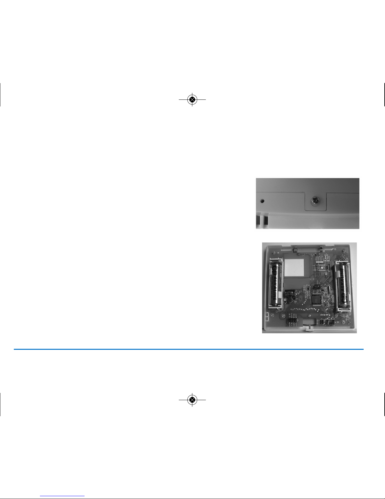
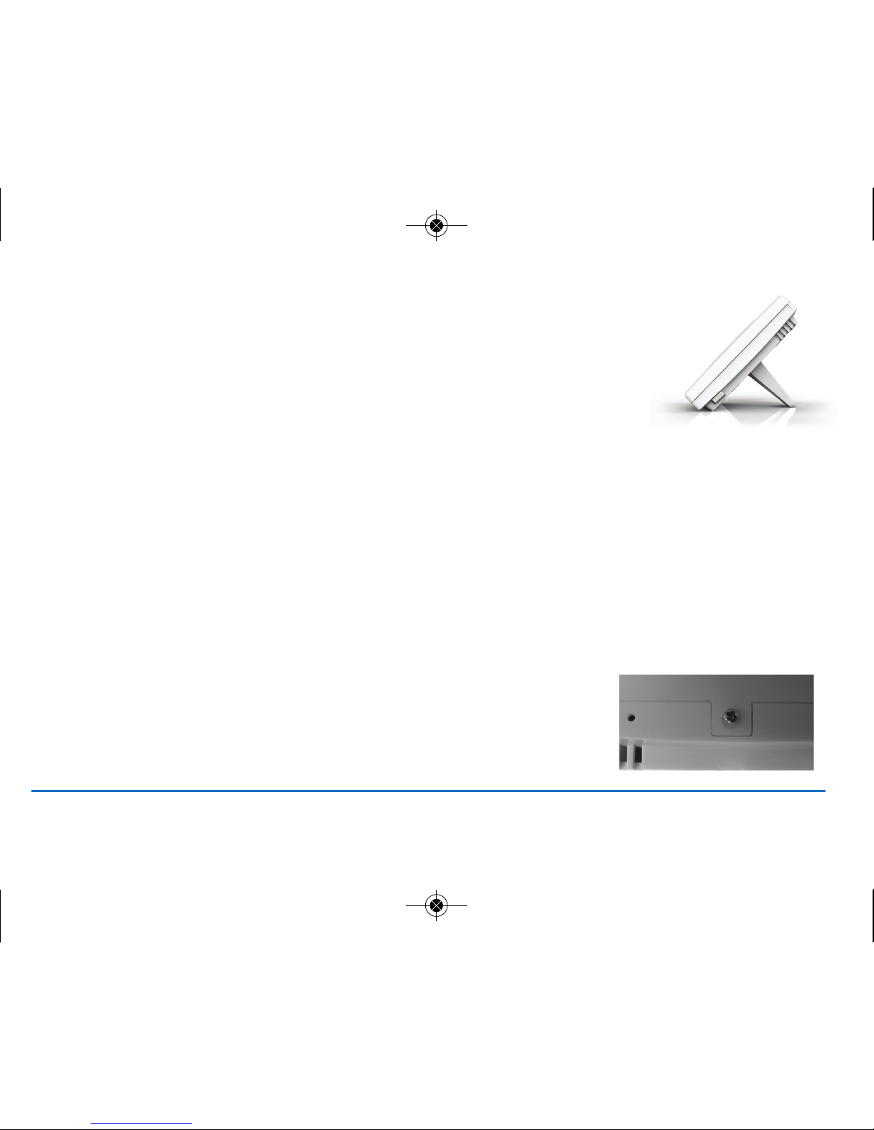
Note: If you do not wish to mount the ST620 on the wall, use the stand provided and
assemble the ST620 front and back housing. Remember to tighten the screw at the bottom.
Wall Mounting Guidelines
The ST620 should be mounted in a location where the thermostat is accessible, reasonably lit and
free from extremes of temperature and draughts. Do not mount the thermostat on an outside wall,
above a radiator or in a location where it may be subjected to direct sunlight.
The ST620 should be mounted in a location where it will not come into contact with moisture or
condensation as this can affect the Touch Ring operation.
To ensure trouble free reception for both the Radio Controlled Clock (RCC) and the Radio Frequency (RF) signal. Always ensure
that the programmable thermostat is mounted away from any possible sources of interference (such as radios, TV sets,
computers, etc.), and is not mounted on or in close proximity to large metal objects. Installing the ST620 in enclosed areas such
as cellars and basements is not recommended.
NOTE: The ideal position to locate the ST620 is about 1.5m above floor level.
RF Transmission
The receiving range between ST620 and the RF Boiler Control is around 100 metres in open air, however many factors can affect
the RF transmission and shorten the operating distance, e.g. shielding by thick walls, foil back plasterboard, metal objects
such as filing cabinets, general RF interference, and so on.
The operating range is generally around 30 metres, which is large enough for most
household applications.
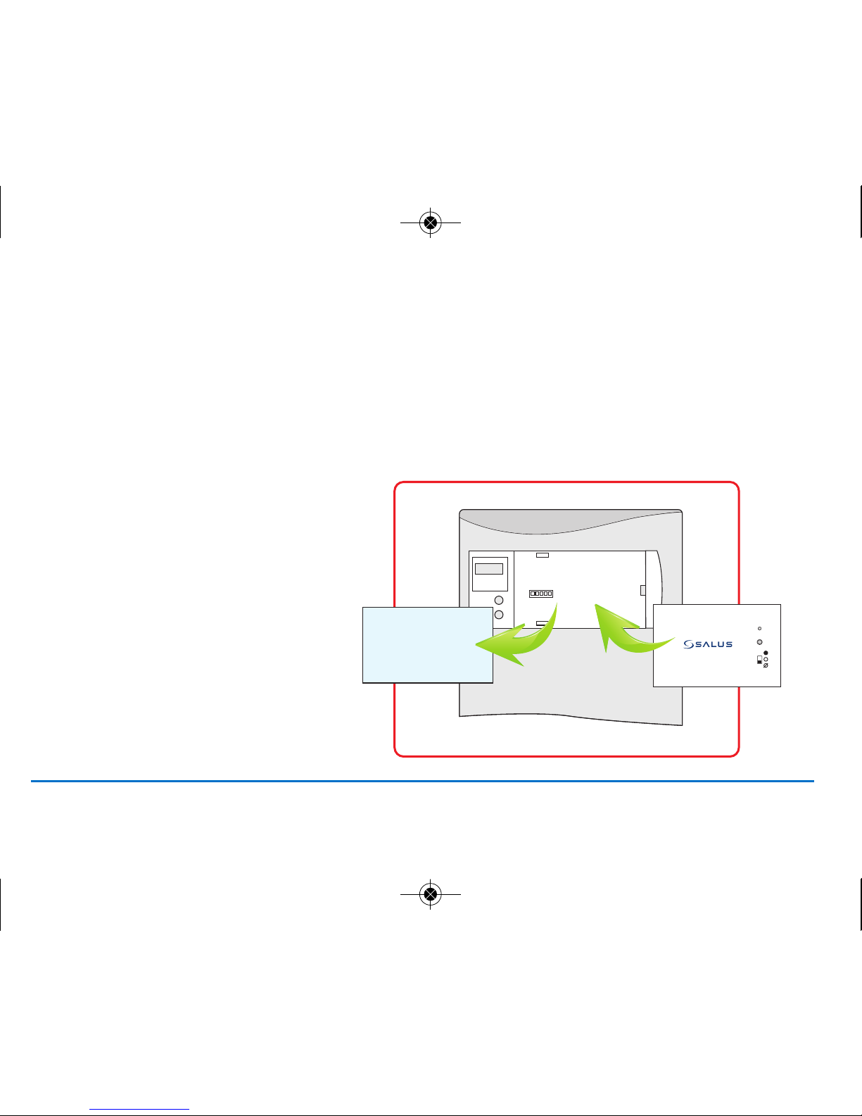
Mounting the Back plate
Use the screws and anchors supplied to mount the ST620 back plate in your chosen
position. Now attach the ST620 front fascia to the back plate. Remember to tighten the
securing screw
ST620VBC INSTRUCTION MANUAL8
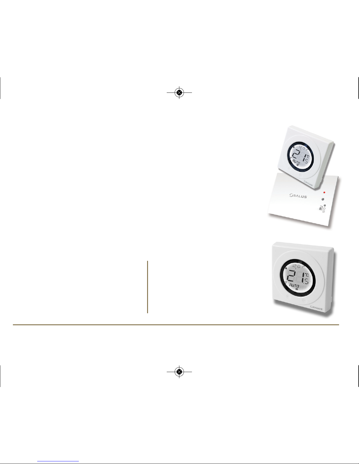
SURFACE MOUNT STAND SUPPLIED
Salus ST620VBC Manual 008_89 09/02/2012 14:00 Page 8

Mounting the RF Integral Boiler Control to the boiler
DANGER!
• 24V & 230V: Do not Touch Electrical Components or circuits
• Isolate mains electricity supply before starting any work and observe all relevant safety
precautions.
• Follow electro static discharge precaution. Do not touch any visible PCB parts or components.
1. Switch off the boiler at its main supply.
2. Remove cover panel or existing control.
3. Insert the integral boiler control ensuring
correct location of the rear Connection pins.
9ST620VBC INSTRUCTION MANUAL
Salus ST620VBC Manual 008_89 09/02/2012 14:00 Page 9

ST620VBC INSTRUCTION MANUAL10
4. Before switching the boiler on at its mains supply,
ensure the module switch is in the OFF position.
5. To ensure the boiler control is connected properly,
please now move the switch to ON .
The boiler should now go on and the LED on the
your boiler control should illuminate
Salus ST620VBC Manual 008_89 09/02/2012 14:00 Page 10

6. Now move the switch back to AUTO .
11ST620VBC INSTRUCTION MANUAL
RF COMMUNICATION
Your ST620 comes already paired with the integral boiler control. This means that the ST620 will communicate with
integral boiler control straight away.
Testing the ST620 RF communication
Press the touch ring anywhere (except the OK and Arrow keys) to enter manual override mode. The current set
temperature will be displayed on the LCD, now press the touch ring again and move your finger clockwise to increase
the displayed temperature to 35 deg. Now press the OK button, your boiler should now fire and the LED on the integral
boiler control should be illuminated.
If you find that the LED on the integral boiler control and the boiler are already on, double check you have the integral
boiler controls selector switch in the AUTO position. If the switch is in the AUTO position follow the instructions above
but decrease the temperature to 5ºC. The LED and boiler should go off.
Salus ST620VBC Manual 008_89 09/02/2012 14:00 Page 11

To stop testing the RF communication press and hold the arrow key on
the ST620 for 2 seconds – this will return the ST620 to AUTO mode. You
can now proceed to the user controls section on page 15.
Manual Setup of RF Communication
If you find that your ST620 will not communicate with integral
boiler control please follow the steps below:
1. Ensure the switch on the RF integral boiler
module is in the AUTO
2. Gently press and hold the SYNC button with a blunt
object. After 3 seconds the Boiler Control LED will flash
once every second to indicate it is ready to pair and
ready to receive a signal from the ST620. The Boiler
Control will remain in pairing mode for 12 minutes.
ST620VBC INSTRUCTION MANUAL12
Salus ST620VBC Manual 008_89 09/02/2012 14:00 Page 12

3. Activate ST620 into pairing mode. To access the Menu
screens on the ST620RF, press the OK key twice. The first
menu displayed is the PROGRAM menu:
4. Use the Touch Ring to scroll through the Menus
to locate the pair option then press OK key
5. Press OK key again activate pairing mode.
PAIR will stop flashing and the pair icon will appear
6. The display will change to show a rundown timer:
13ST620VBC INSTRUCTION MANUAL
Salus ST620VBC Manual 008_89 09/02/2012 14:00 Page 13

The display counts down for a period of 10 minutes, with the RF Signal indicator flashing while the signal is being
transmitted. The RF address code will be generated randomly.
When the Boiler Control successfully receives a signal from the ST620 during the pairing operation, the Boiler Control
will store the generated address code into its internal memory. The LED will pulse once every second and go out if the
code is stored correctly, or pulse twice every second if this was unsuccessful. If pairing is unsuccessful then you will have
to re-start the pairing process.
Additional Information
Pressing the Reset button on the ST620 will clear the RF address code and restore the default code which will be saved
into the internal memory of the unit. Replacing the ST620 batteries will not affect the RF code setting, pressing and
holding the SYNC button on the Boiler Control will however clear the RF address code saved into the internal memory,
and switch the Boiler Control into pairing mode, as previously described.
SERVICE and CONTROL functions
If you require to use the above functions of the ST620 during this Installation, please refer to pages 33 and 34.
ST620VBC INSTRUCTION MANUAL14
Salus ST620VBC Manual 008_89 09/02/2012 14:00 Page 14

USER CONTROLS
Integral RF Boiler Control
A – LED
This LED will be on when the ST620 is demanding heat.
B – Mode Switch
ON – Boiler will be on continuous
AUTO – will follow time and temperature program in the ST620
OFF – Boiler is off
C – SYNC Button - This is used only for pairing the RF communications.
ST620 Overview
The status and operation of the ST620 is clearly shown
on the large Liquid Crystal Display (LCD).
This display allows the user to see at a glance the current status of the heating
system, as well as a clear indication of the current room temperature.
15ST620VBC INSTRUCTION MANUAL
Salus ST620VBC Manual 008_89 09/02/2012 14:00 Page 15

Indicator Description Function
Clock Display Displays the day and time
Temperature indicator Displays set or measured temperature
Alphanumeric Display Displays menu and other status messages
Programme Number Displays the number of the
indicator active (selected) programme
Heat Mode indicator Indicates heating output is turned on.
Holiday indicator Indicates Holiday operation mode is selected
Battery Status Indicates battery is low
RF Signal indicator Indicates the unit is transmitting
a wireless signal
RCC indicator Indicates unit is searching for radio controlled clock signal
Service indicator Indicates Service function is active
Frost Mode indicator Indicates frost setting is turned on
Touch Lock indicator Indicates touch lock is activated
There are few user controls for the ST620, making the programmable thermostat very easy to operate. The controls are a Touch
Ring (which surrounds the user display), two touch sensitive buttons, a reset button and a slide operated switch mounted on
the side of the thermostat. These controls are shown below, along with a description of each of their functions.
ST620VBC INSTRUCTION MANUAL16
Salus ST620VBC Manual 008_89 09/02/2012 14:00 Page 16

USER CONTROL FUNCTION SUMMARY ST620:
Key / Operation Functions
Touch Ring (move clockwise) Increases the set temperature and scrolls through the menu selection
Touch Ring (move anti- clockwise) Decreases the set temperature and scrolls through the menu selection
OK Key Enters Menu or confirms a menu selection
Arrow (Back) Key Single touch- sets the unit back 1 step.
Hold for 2 seconds sets unit back to normal mode
Reset Button Resets the thermostat to default (original factory) settings
Slide Switch Activates and deactivates the key lock function (prevents accidental changes)
17ST620VBC INSTRUCTION MANUAL
Salus ST620VBC Manual 008_89 09/02/2012 14:00 Page 17

Programme Output Weekday Weekend
1ON 6:00AM 6:00AM
TEMP 21ºC 21ºC
2ON 8:00AM 8:00AM
TEMP 14ºC 14ºC
3ON 11:00AM 11:00AM
TEMP 21ºC 21ºC
4ON 1:00PM 1:00PM
TEMP 14ºC 14ºC
5ON 4:00PM 4:00PM
TEMP 21ºC 21ºC
6ON 9:00PM 9:00PM
TEMP 14ºC 14ºC
BASIC OPERATION
Getting Started………..
ST620 Programmable room thermostat
Your ST620 comes with factory set default
program. The temperature and time settings
have already been set. If the default program
meets your requirement there is no need to
change the default program.
Reviewing the Set Temperature
1. AUTO mode is when the thermostat is displaying the room temperature.
2. If you press the Touch Ring anywhere except the OK and Arrow keys
you can check the set temperature setting.
This will display the current set temperature. The set temperature will be displayed
for two seconds before the LCD changes to display the room temperature again.
The ST620 will go back to AUTO mode without changing the set
temperature after 10 seconds of inactivity, or after pressing the Arrow key.
ST620VBC INSTRUCTION MANUAL18
Salus ST620VBC Manual 008_89 09/02/2012 14:00 Page 18

Manual Override
When the ST620 is in AUTO mode, press the Touch Ring anywhere except the OK and
Arrow keys to enter the manual override mode. The currently set temperature will be
displayed on the LCD and will flash.
When the set temperature is flashing, press the touch ring and move your finger clockwise
to increase the set temperature, or anti-clockwise to decrease the set temperature. Press OK
at any time to confirm the selection.
NOTE: The ST620 will go back to AUTO mode without changing the set temperature after
10 seconds of inactivity, or after pressing the Arrow key.
When the ST620 is operating in Manual Override mode, the LCD will display MANUAL
instead of AUTO. The manual setting will remain in effect until the next programme time
is reached, or the Manual Override mode is cancelled.
Manual Override mode can be cancelled at any time by pressing and holding the Arrow key
for 2 seconds – this will return the ST620 to AUTO mode.
19ST620VBC INSTRUCTION MANUAL
Salus ST620VBC Manual 008_89 09/02/2012 14:00 Page 19

RF Boiler Control
When the switch on the Boiler Module is in the AUTO position, the
Boiler Control will automatically receive the RF signal from the
ST620 and control the module output so that it switches the boiler
accordingly.
The user can also move the switch to the MANUAL ON position;
when in this mode, the boiler will be always turned on and the LED
indicator will also be lit constantly.
The user can also move the switch to the OFF position; when in this
mode, the boiler will not receive a signal from the ST620 and the
LED indicator will also be lit constantly.
ST620VBC INSTRUCTION MANUAL20
Salus ST620VBC Manual 008_89 09/02/2012 14:00 Page 20
Other manuals for ST620VBC
1
Table of contents
Other Salus Thermostat manuals

Salus
Salus VS30W User manual

Salus
Salus HTRP230V User manual

Salus
Salus ST620RF User manual

Salus
Salus RT 10 User manual

Salus
Salus RT300RF User manual

Salus
Salus S Series User manual

Salus
Salus ST880ZB User manual

Salus
Salus WBNTSQ61024 Quantum User manual

Salus
Salus RXRT505 User manual

Salus
Salus 091FLRF User manual

Salus
Salus FC600 User manual

Salus
Salus HTRP-RF(50) User manual

Salus
Salus ERT20RF User manual

Salus
Salus AHTR5024 User guide

Salus
Salus EP101 User manual

Salus
Salus RT500 User manual

Salus
Salus RT100 User manual

Salus
Salus RT310 User manual

Salus
Salus QUANTUM SQ610RF User manual

Salus
Salus ERT50T Triac User manual