Climax Vesta ESGW Series User manual

November 28, 2019

Table of Contents
1. INTRODUCTION __________________________________________________________________ 1
2. DEVICE MANAGEMENT ____________________________________________________________ 2
2.1. IDENTIFYING THE PARTS: _____________________________________________________________ 2
2.2. THE POWER SUPPLY:________________________________________________________________ 3
2.3. SYSTEM REQUIREMENTS:_____________________________________________________________ 3
3. GETTING STARTED _______________________________________________________________ 4
3.1. SYSTEM DEPLOYMENT_______________________________________________________________ 4
3.2. INSTALLING THE CONTROL PANEL _______________________________________________________ 4
3.3. SOFTWARE INSTALLATION_____________________________________________________________ 4
4. CONNECTION TO PANEL WEBPAGE _________________________________________________ 7
5. DEVICE MANAGEMENT ____________________________________________________________ 9
5.1. LEARNING ________________________________________________________________________ 9
5.2. LEARN RULE _____________________________________________________________________ 17
5.3.WALK TEST ______________________________________________________________________ 19
5.4. EXCLUSION ______________________________________________________________________ 20
5.5. Z-WAVE TOOL ____________________________________________________________________ 21
5.6. PSS CONTROL ___________________________________________________________________ 22
5.7. UPIC CONTROL___________________________________________________________________ 24
5.8. SURVEILLANCE ___________________________________________________________________ 25
5.9. GROUP CONTROL _________________________________________________________________ 28
6. PROGRAM THE SYSTEM__________________________________________________________ 29
6.1. PANEL CONDITION _________________________________________________________________ 29
6.2. PANEL SETTINGS __________________________________________________________________ 31
6.3. PIN CODE_______________________________________________________________________ 35
7. NETWORK SETTINGS ____________________________________________________________ 36
7.1. NETWORK _______________________________________________________________________ 36
7.2.WIRELESS (OPTIONAL)______________________________________________________________ 37
7.3. UPNP __________________________________________________________________________ 38
8. SYSTEM SETTINGS ______________________________________________________________ 39
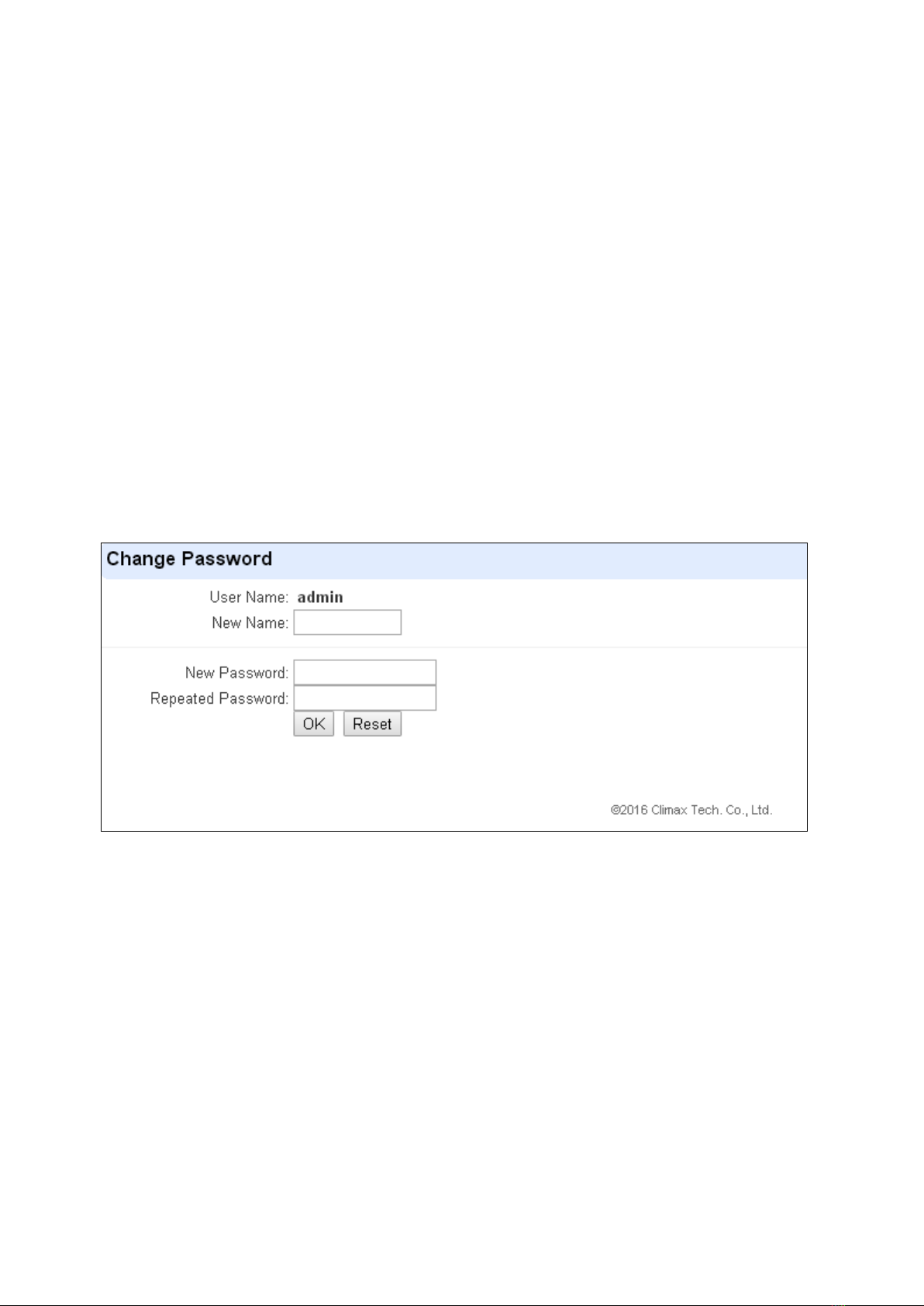
8.1.ADMINISTRATOR SETTING____________________________________________________________ 39
8.2. HOME AUTOMATION ________________________________________________________________ 40
8.3. SCENE _________________________________________________________________________ 45
8.4. REPORTING______________________________________________________________________ 47

8.5. CODE SETTINGS __________________________________________________________________ 49
8.6. SMTP SETTING___________________________________________________________________ 51
8.7. MEDIA UPLOAD ___________________________________________________________________ 52
8.8. POLLING ________________________________________________________________________ 53
8.9. XMPP__________________________________________________________________________ 54
8.10. DATE &TIME ____________________________________________________________________ 55
8.11. DYNAMIC DNS___________________________________________________________________ 56
8.12. TEST IP________________________________________________________________________ 57
8.13. FIRMWARE UPGRADE______________________________________________________________ 58
8.14. FACTORY RESET _________________________________________________________________ 59
8.15. BACKUP &RESTORE ______________________________________________________________ 60
8.16. SYSTEM LOG____________________________________________________________________ 61
9. EVENT & HISTORY _______________________________________________________________ 62
9.1. CAPTURED EVENTS ________________________________________________________________ 62
9.2. REPORTED EVENTS ________________________________________________________________ 63
9.3. EVENT LOG ______________________________________________________________________ 64
9.4. DEVICE HISTORY __________________________________________________________________ 65
10. APPENDIX ______________________________________________________________________ 66
10.1. COMMUNICATION PROTOCOL &FORMAT ________________________________________________ 66
10.2. EVENT CODE____________________________________________________________________ 67

1
1. Introduction
This section covers unpacking your ESGW IP Gateway Control Panel. Refer to later chapters for
information on setting up and configuring the system over the Web Page in more detail.
The Control Panel utilizes ZigBee Pro Home Automation 1.2 profile is compatible with all ZigBee
devices of same protocol on the market produced by other manufacturers. The advanced IP
Security System with fully integrated TCP/IP technology and Ethernet connectivity is able to take
full advantage of new advances in IP Home Security and Home Automation and multi-path
signalling.
Remote Control of the panel is achieved by registering the panel in remote server to view panel
status, receive alarm report and manage Home Automation in one complete solution.

2
2. Device Management
2.1. Identifying the parts:
1. Function Button & System Mode LED (Red/Blue)
Function Button:
Press and hold for 3 seconds –Enable WPS Protocol
Press and hold for 10 seconds –Enter Learning Mode
Press once under Learning Mode –Exit Learning Mode
Press and Hold then applyAC Power –Factory Reset
LED:
Red On –Away Arm
Red Flash –Home Arm
Blue On –Disarm
2. Network LED (Amber)
Amber On –Network Cable Unplugged and WiFi Disconnected
Amber Flash –Disconnected from Server
Off –Network Normal
3. System Status LED (Red/Amber)
Red On –System Alarming
Red Flash –Alarm In Memory
Amber On –Fault Exists in Sytem
Amber Flash –System under Learning Mode
Off –System Normal
4. Wall Mounting Holes
5. DC Jack
For connecting DC 5V 1A switching power
6. USB Port
- Z-Wave dongle USB port
7. Ethernet Port

3
2.2. The Power Supply:
An AC power adapter is required to connect to a wall outlet. Be sure only to use an adapter with
the appropriate AC voltage rating to prevent component damage. DC 5V 1A switching power
output adaptor is generally used to power the Control Panel for standard version.
2.3. System Requirements:
The system requires a TCP/IP network environment for you to connect to the Control Panel for
system programming. Hardware requirement for programming the panel vial Local Area
Network (LAN) webpage:
Microsoft Windows 8 or Windows 10 operating system.
Microsoft Internet Explorer 6.x, or later and Mozilla Firefox 3.0 compatible.
CPU: Intel Pentium II 266MHz or above
Memory: 32MB (64MB recommended)
VGA resolution: 800x600 or above

4
3. Getting Started
Read this section of the manual to learn how to set up your ESGW series Control Panel and
program System Settings over the Web page.
3.1. System Deployment
The Control Panel is designed to be placed on desktop, follow guidelines below when planning
installation location:
The Control Panel requires Ethernet connection for system programming, alarm reporting
and remote control.
The Control Panel should be installed at a location that is hidden from outside view.
The Control Panel should be protected by sensors so that no intruder can reach the Control
Panel without activating first activating sensor.
3.2. Installing the Control Panel
Step 1. For configuration and operation of Control Panel via Ethernet, connect the IP cable to
the RJ-45 connector.
Step 2. Connect the Power Adaptor to a Wall Outlet and the other end to the Control Panel.
After several seconds, the System Mode Blue LED will turn on to indicate system is
now functional.
Step 3. The Control Panel can be mounted on wall with its wall mounting holes. Use the two
holes to mark location on the wall, drill holes into wall and install screw at mounting
location, then hang the Control Panel onto the screws.
3.3. Software Installation
※THIS INSTALLATION IS ONLY REQUIRED FOR FIRST TIME USER ※
1. RUNNING THE FINDER SOFTWARE
The Finder software is required for your computer to identify the control panel on the LAN.
Step 1. To download Finder software, open your browser and type below URL in the
address bar: http://www.climax.com.tw/climax-download-finder.html.

5
Step 2. After download, install the software and follow on-screen instructions to
.complete installation.
Step 3. Follow on screen instruction to complete installation
Step 4. Once complete, the Finder icon will be displayed on your desktop.
Step 5. Double click on the “Finder.exe” to start the software. Finder will automatically search
for control panel on the LAN and display its information. If available, the panel’s LAN
IP address, Firmware version and MAC address will be displayed
Step 6. If the panel information is not displayed, check panel power and Ethernet connection
and click on “Search”to update the panel information.

6
Step 7. (Optional)You can choose to edit the panel’s network setting by clicking on the panel
column, then click “Configure Setting”
The LanType is default to DHCP and does not require manual input of
IP/Netmask/Gateawy/DNS setting. If you wish to configure these setting manually,
change LanType to Static.
After finish changing network setting, enter the user name (default: admin) and
password (default: cX+HsA*7F1) then click OK to confirm. The user name and
password can be changed later in panel configuration webpage
Step 8. Click the panel information column and click on “Open Web Page”, or double click on
the panel column to link to the panel configuration webpage. Your default browser will
start automatically to connect to the LAN IP displayed in Finder.

7
4. Connection to Panel Webpage
For first time setup, webpage connection is only available within 1 hour after the panel is
powered on; if the panel has been powered on for more than 1 hour. Webpage access will
be disabled. Reboot the panel to enable webpage function again.
Change default password after login to gain unrestricted webpage access.
Step 1. Select the Control Panel in the Finder software and click on “Open Webpage”to
connect to panel webpage.
Alternatively, enter the Control Panel IP address displayed in Finder into your
browser’s address section and proceed.
Step 2. Enter the User name & Password to proceed
Default user name: admin
Default password: cX+HsA*7F1
Step 3. You will enter change password page. Enter and repeat a new password (username
change is optional), take care that both username and password are case sensitive.
Click OK to confirm.
Step 4. Upon confirming new username and password. You will enter panel Welcome page.
The panel will prompt you to re login with new username and password.

8
The Welcome page displays current control panel firmware version information
according to different panel model and MAC address.
<
<I
IM
MP
PO
OR
RT
TA
AN
NT
T
N
NO
OT
TE
E>
>
If the default login password is not changed, webpage access will be disabled 1 hour
after power on. Reboot the panel and changed password to allow unrestricted
webpage access.

9
5. Device Management
5.1. Learning
This feature is for you to add new devices into the Control Panel.
The panel can support a maximum of 160 devices in two areas (80 devices each area.).
Up to 6 IP Cameras can be included in the panel.
If the panel has Z-Wave compatibility (with Z-Wave Dongle), it can also support Z-Wave
devices
<
<I
IM
MP
PO
OR
RT
TA
AN
NT
T
N
NO
OT
TE
E>
>
The Control Panel built-in ZigBee module supports up to 40 ZigBee devices by itself. If
you wish to include more than 40 ZigBee devices into the Control Panel, you must add
extra ZigBee Routers into the Control Panel’s ZigBee network to increase the network’s
maximum device capacity.
5.1.1. Add Sensor
Step 1. Click on “Learning/Inclusion”on the tool bar and then the following screen will be
displayed.
Step 2. Click on “Start”
Step 3. The Control Panel will automatically search for devices and include the device in the
network. (Please refer to your device manual for detail). When the Control Panel
successfully includes a new device in the network, the device information will be
displayed accordingly on the webpage.
Step 4. When the system receives the signal from your device, the screen will display its
information for selection.
Step 5. Click “Add”(highlighted in red box) to include this particular sensor into the system. If
the sensor you wish to learn into already exists in the system, the sensor information
will be displayed in the Learned Device section. If not, the sensor information will be
displayed in the Detected Device section.

10
<
<N
NO
OT
TE
E>
>
Z-Wave devices requires an additional Z-Wave Dongle.
Step 6. If the device is successfully learnt into the system, the added device will be displayed in
the “Learned Device”section as below.
5.1.2. Local Learning
Press and hold the Function Button at the top of Control Panel for 10 seconds to enter learning
mode, then transmit signal from your accessory devices. When the signal is received the panel
will add the device into panel and assigned the device to to Area 1 automatically. To exit local
learning mode, press the function Button once.

11
5.1.3. Edit Devices
Step 1. To edit device setting, go to “Panel” webpage and click “Edit” after the device column
under the Device List section.
Step 2. You device information and setting will be displayed. Programming the settings
according to instructions below and click OK when completed to confirm change.
<
<N
NO
OT
TE
E>
>
Press “Default”to reset all parameters to default values.
Press “Reset” to re-enter all the information.
Press “Cancel” to exit the screen and returns to Panel Condition Page.

12
Step 3. Edit your device setting and information according to instruction below. Click “OK”to
save your new changes when finished. Alternatively, click “Default”to reset all
parameters to default values or click “Reset” to re-enter all the information.
Name: Enter a name for the device.
Area: Select the area which the device belongs to.
Zone: Select the Device zone number.
Bybass: this function allows user to deactivate (bypass) the selected device.
If bypassed, then the Control Panel will not respond at all when the sensor is triggered.
If bypassed, the system can be armed directly regardless the device’s fault situation.
However, its fault situation will still be monitored, logged and displayed in the history
records webpage.
Latch Report (Only for Remote Controller or Door Contact with Set/Unset attribute
enabled):
Latch Report ON = Whenever the system is armed, home armed or disarmed, the

13
Control Panel will report the arm/disarm event by the particular device
Latch Reprot OFF = Whenever the system is armed, home armed or disarmed, the
Control Panel will NOT report the event.
Set/Unset: For Door Contact only. This function allows Door Contact to control system
mode..
Normal Close = The system will be armed when the Door Contact is opened, and
disarmed when Door Contact is closed.
Normal Open = The system will be armed when the Door Contact is closed, and
disarmed when Door Contact is open.
24H: this function enables the sensor to report an selected alarm event whenever it is
triggered regardless of system mode..
Disarm/ Full/ Home 1/ Home 2/ Home 3 response: if the system is in the disarm /
Full/home1//home2/home3 mode, when a sensor is triggered, it will respond according
to the attribute you set.
Trigger Response: When the device is triggered, the Control Panel will activated
pre-programmed scene setting. Please refer to Scene webpage for detail.
Exit: if No Response is ticked, the sensor does not repond to any trigger when the
system under Exit Delay Time 1/2. If No Response is not ticked, the sensor will raise
burglar alarm and report immediately when triggered during Exit Delay Timer.
Attribute List:
No Response
When a sensor with No Response is triggered, the Control Panel will not
respond.
Start Entry Delay 1/ Start Entry Delay 2
When the system is under Full Arm or Home Arm mode, if a sensor with Start
Entry Delay 1/2 attribute is triggered, the system will start an entry countdown
period to give enough time to disarm the system.
When the Control Panel is in the Disarm mode, if a sensor with Start Entry Delay
1/2 attribute is triggered, the system will immediately report a burglar interior
alarm (CID code: 132).
When the Control Panel is in the Full Arm mode, if a sensor with Start Entry
Delay 1/2 attribute is triggered, the Entry Delay 1/2 timer starts counting down.
If no correct pin code is entered during the entry delay timer to disarm the system,
the Control Panel will report a burglar perimeter alarm (CID code:131)
immediately after entry delay timer 1/2 expires.
When the Control Panel is in the Home Arm 1/2/3 mode, if a sensor with Start
Entry Delay 1/2 attribute is triggered, the Entry Delay 1/2 timer starts counting
down. If no correct pin code is entered during the entry delay period to disam
the system, the Control Panel will report a burglar interior alarm (CID code: 132)
immediately after entry delay timer 1/2 expires.
Chime
When a sensor set to Chime is activated, the system will sound a Ding-Dong
Door Chime sound to indicate.
Burglar Follow
When the system is in Full Arm or Home Arm mode mode, if a sensor set to

14
Burglar Follow is triggered, the Control Panel will report a burglar alarm
immediately.
When a Start Entry sensor is triggered and the system is under Entry Delay Timer
countdown, if a sensor set to Burglar Follow is triggered, the Control Panel will
wait until the Entry Delay Timer expires before activating a burglar alarm. If the
system is disarmed before the timer expires, the Control Panel will not activate
alarm.
Burglar Instant
When the system is under Full arm or Home Arm/ Disarm / Entry Time mode, if a
sensor set to Burglar Instant is triggered, the Control Panel will report a burglar
alarm immediately.
Burglar Outdoor
When the system is in Full Arm or Home Arm / Disarm / / Entry Time mode, if a
sensor set to Burglar Outdoor is triggered, the Control Panel will report a burglar
outdoor event immediately.
Apply Scene
The attribute is for Trigger Response only. You can select a Home Automation
Scene number with this function. When the device is triggered/activated, the
Control Panel will execute the actions programming in the Scene accordingly. For
more information, please refer to 8.3. Scene.

15
5.1.4. Delete Devices
Step 1. To delete a sensor, choose “Delete” under “Panel” section.
Step 2. A message “Delete success”is displayed and the sensor you choose is deleted
successfully.

16
5.1.5. Identify ZigBee Device
The Identify function is available for ZigBee device only, it can be used to locate ZigBee devices
after learning.
For battery powered ZigBee devices, the identify fuction should be used within 1 minute after
pressing device button, or 3 minute after learning in the device. Otherwise due to ZigBee
network mechanisms, the device may not be able to receive signal successfullly from panel.
AC powered ZigBee devices do not have such limits and you can use Identify function anytime.
Step 1. Click “Identify”under the Device List after the device column entry.
Step 2. If the ZigBee device receives signal successfully, the webpage will display a success
message and the ZigBee device LED indicator will flash 10 times to confirm.
<
<N
NO
OT
TE
E>
>
If a timeout message is displayed on webpage, it means the device did not receive
signal from Control Panel, please check ZigBee device range from panel and make
sure to follow instruction above about Identifying battery powered ZigBee devices.

17
5.2. Learn Rule
You can enter the sensor ZigBee MAC address manually to assign area and zone number to
this sensor. Sensors learned with pre-assigned rule will be put under the area and zone number
you specified. This function does not work with Z-Wave devices or IP Camera
Step 1. Under the Learn Rule menu, click Add Learn Rule.
Step 2. You will see the Add Learn Rule menu.
Step 3. Select Area and Zone number for this device.
Step 4. Select ZigBee.
Step 5. Key in the ZigBee MAC info
Step 6. Select a ZigBee Device Type
Step 7. Enter a preferred name for sensor (up to 31 letters or numbers).
Step 8. Press “OK”to save.
Step 9. If the process is successful, the screen will display “Updated Successfully.”You can
then check, edit or delete the rule under the Learn Rule menu.
Step 10 Repeat the steps to add more rules.
Table of contents
Other Climax Gateway manuals
Popular Gateway manuals by other brands

Johnson Controls
Johnson Controls MAP Series installation instructions

Helmholz
Helmholz PN/CAN gateway quick start guide

ABM
ABM ABM1-RUCM-C4 installation manual

AudioCodes
AudioCodes MediaPack 1 Series Quick setup guide

RTA
RTA 460MSQT-NNA1 Product user guide

ZyXEL Communications
ZyXEL Communications ZYWALL USG 20 manual

FingerTec
FingerTec i-Kiosk 100 Plus installation guide

Advantech
Advantech EKI-1242PNMS quick guide

AudioCodes
AudioCodes MediaPack MP-263 quick guide

Patton
Patton SN4112 quick start guide

B+B SmartWorx
B+B SmartWorx SmartSwarm 342 Quick start guides

ZyXEL Communications
ZyXEL Communications VMG4380-B10A user guide