Clinch Rivets CR-2 User manual
Page 1 of 11
CR-2 Instruction Manual
Effective Dec 19th 2013

Page 2 of 11
Contents:
Tool Properties
Technical Specifications
Safety Instructions
Tool Preparation
Operating Instructions
Maintenance and Service
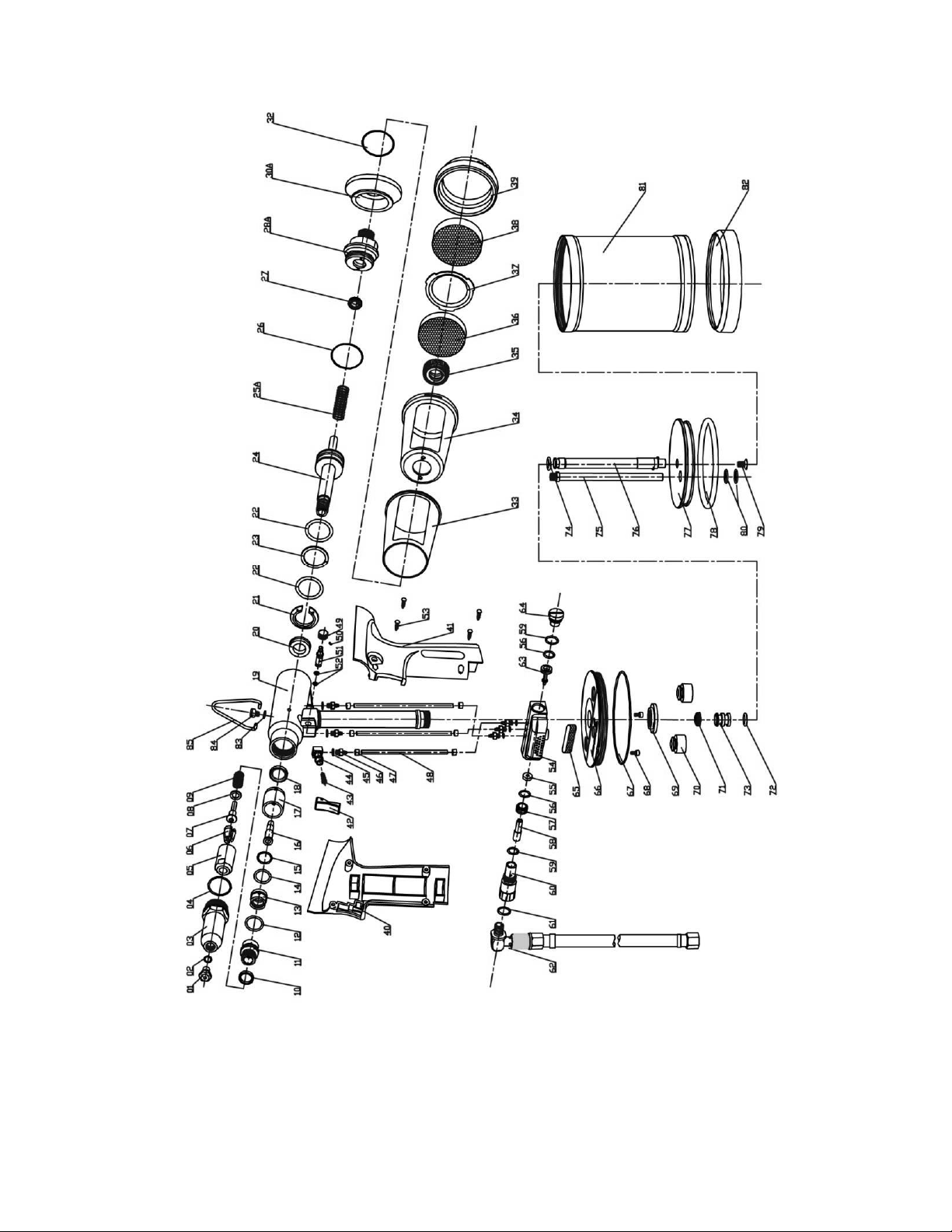
Exploded Drawing
Parts List
3
4
5
6
7
8
10
11

Page 3 of 11
Tool Property:
Light weight
High-speed operation, high power
Low noise
Shock absorption
Long stroke
Easy maintenance
Sets standard rivets up to 3/16” diameter into any materials
Designed for high strength blind rivet with 3/16” diameter i.e. monobolt, interlock, etc
Adjustable vacuum system for powering on and off mandrel retention function
The tool can operate without the mandrel container
The tool can mount the rivet in single operation
Effective air pressure is 44 to 102 psi
Max pull force is 2473 lb
CNC machined quality components ensures long life
Mandel container can be turned easily for cleaning

Page 4 of 11
Technical Specification:
Rivet size: Diameter 0.125 –1.89 inches for standard rivets
Diameter 0.189 inches for high strength structural blind rivet
Air pressure: 11.0 –15.4 lbf
Stroke: 0.787 inches
Pull force @ 5 Bar: 2472 lb
Weight: 3.20 lb

Page 5 of 11
Safety Instructions:
Please read the following instructions carefully.
Never dissemble the tool without reading the following safety instructions.
Always use the tool in accordance with the specified safety instructions. Direct any
queries regarding safety and operation to our company.
Never connect the tool to any medium other than compressed air. Set the air pressure
between 42 to 101 psi.
Do not use the tool for purpose other than installing rivets.
The tool must be maintained in a safe working condition at all times and examined at
regular intervals for damage.
Do not dismantle this tool without prior reference to the maintenance and service
instructions.
Always disconnect the air pipe from the tool inlet before maintenance and service.
Do not point tool towards people or persons.
When using the tool, wear safety glasses.

Page 6 of 11
Tool Preparation:
The tool must be connected to an air filter. This unit filters the compressed air to separate dirt
and condensate. A pressure regulator with a preferred setting of 87 psi must be installed. Air
supply must be free of moisture and particles.
Use dry and clean materials (hose, couplings, fittings, etc.) to connect the tool to the filter.
Check for leakage in the compressed air supply. If here is leakage, replace the damaged hoses
or coupling. Drain the condensate from the filter. Also check the dirt filter.
Check the compressed air supply pressure. The tool must be fitted with correct nosepiece (01)
and pusher (07) before operating.

Page 7 of 11
Operating Instruction:
1. Connect the air supply, switch ON/OFF vale (48) to ON position. (See figure 1)
2. Adjust the vacuum security system clockwise or counter-
clockwise. Air suction will allow the rivet to be held in any orientation.
(See figure 2)
Attention: If you don’t want to use vacuum system, you can turn
vacuum security system clock wise and turn it off.
3. Direct the riveter with rivet to the hole and then pull the trigger. The stems
automatically reverse to the collector and the rivet is set.
Fig 1
Fig 2

Page 8 of 11
Priming:
After 100,000 cycles, the stroke is reduced and rivets are not set by one operation, then the
tool needs to be oiled. Please use the attached bottle of lubrication oil in the box.
1. Disconnect air supply to tool and switch ON/OFF valve (48) to OFF position.
2. Remove seal screw (84) and seal (83). (See figure 3)
3. Screw the priming pump oil into the bleed screw hole.
Press down and release several times until resistance is felt.
(See figure 4)
4. Remove the priming pump and the excessive oil will
flow out. Clean out the excessive oil and replace the seal
screw and seal.
Fig 3
Fig 4

Page 9 of 11
Head Cleaning and Oiling:
Every 10,000 cycles the tool should be oil on the jaws. (See figure 5)
1. Disconnect air supply and air valve switch.
2. Dismantle the riveter head by wrench.
3. Use wrench to disassemble head components and cleaning these parts, and then
lubricate them before assembling. (See figure 5)
Trouble Shooting
Symptoms
Possible Causes
Solutions
The jaws cannot release the
mandrel
The nosepiece, jaws, jaw
carrier and out cylinder
may not be assembled
correctly
The spring may be worn
out or broken
The oil may be insufficient
There is oil or air leakage
somewhere
Check the nosepiece,
jaws, jaw carrier and out
cylinder
Replace the defective
coupling and components
Add hydraulic oil
The rivet cannot be put into
the tool nosepiece
The stem may be
obstructed
The vacuum system may
not be in good condition
Check the jaws
Adjust the vacuum
security system to the
optimal volume
The tool works very slowly or
requires more than one
trigger-pull to set the rivet.
Hydraulic oil level is low
The air pressure is low
The nosepiece is filled
with dust and particles
Add hydraulic oil
Adjust air pressure to the
specific range
Clean and oil
Fig 5
Page 10 of 11

Page 11 of 11
Parts list:
PART NO.
DESCRIPTION
PART NO.
DESCRIPTION
CR-2-01
Nosepiece
CR-2-44
On/Off base
CR-2-02
O-ring (meas. 9*1)
CR-2-45
O-ring (meas.6*1)
CR-2-03
Nosepiece casing
CR-2-46
Air interface
CR-2-04
O-ring (meas.22*2)
CR-2-47
Tie ring
CR-2-05
Jaw housing
CR-2-48
Air tube
CR-2-06
Jaws
CR-2-49
Regulatable button
CR-2-07
Pusher
CR-2-50
Retaining screw (meas.3*3)
CR-2-08
Washer
CR-2-51
Vacuum valve
CR-2-09
Jaw pusher spring
CR-2-52
O-ring (meas.4*6*1)
CR-2-10
Lock ring
CR-2-53
Tapping screw (meas.3*10)
CR-2-11
Housing
CR-2-54
Air valve body
CR-2-12
Polyurethane ring (meas.16*2)
CR-2-55
Air valve ring
CR-2-13
Set nut
CR-2-56
O-ring (meas.9.5*12.5*1.5)
CR-2-14
Polyurethane ring (meas.14.3*2)
CR-2-57
Air valve base
CR-2-15
O-ring (meas.13*16*1.5)
CR-2-58
Subordinate tube
CR-2-16
Vacuum sleeve
CR-2-59
O-ring (meas.11.5*14.5*1.5)
CR-2-17
Seal plastic housing
CR-2-60
Connecting base
CR-2-18
Seal (meas.20.5*13.5*3.5)
CR-2-61
O-ring (meas.14*2.4)
CR-2-19
Head assembly
CR-2-62
On/Off assembly
CR-2-20
Lip seal (meas.14*11*6.3)
CR-2-63
Air valve rod
CR-2-21
Retaining nut
CR-2-64
Screw plug
CR-2-22
O-ring (meas.26.7*30.26*1.78)
CR-2-65
Silencer
CR-2-23
Lip seal (meas.22*30*6)
CR-2-66
Cylinder cover
CR-2-24
Axis
CR-2-67
O-ring (meas.66*2)
CR-2-25A
Restore Spring
CR-2-68
Bolt
CR-2-26
O-ring (meas.35*1.5)
CR-2-69
Rock nut
CR-2-27
EL (meas.8*14.2*5)
CR-2-70
Buffer
CR-2-28A
End cap
CR-2-71
Lip seal (meas.8*14*6)
CR-2-30A
Stem collector adaptor
CR-2-72
O-ring (meas.11.5*1.5)
CR-2-32
O-ring (meas.47*1.5)
CR-2-73
Air tube piston
CR-2-33
Stem collector outer
CR-2-74
Piston ring
CR-2-34
Stem collector body
CR-2-75
Transfer tube
CR-2-35
Retaining nut
CR-2-76
Piston rod
CR-2-36
Silencer
CR-2-77
Cylinder piston
CR-2-37
Stem collector end cap
CR-2-78
O-ring (meas.74.6*86*5.7)
CR-2-38
Silencer
CR-2-79
Bolt (meas.6*10)
CR-2-39
Silencer cap
CR-2-80
O-Ring
CR-2-40
Handle (left)
CR-2-80
Cylinder
CR-2-41
Handle (right)
CR-2-82
Base cover
CR-2-42
Trigger
CR-2-83
BS (meas.5.7*10*1)
CR-2-43
Trigger valve
CR-2-84
Seal screw
CR-2-85
Hook
Note: Part numbers 25, 28, 30, and 62 have been upgraded, and part numbers 29 and 31 were
removed after December 2013.
This manual suits for next models
1
Table of contents
Other Clinch Rivets Rivet Tools manuals

Popular Rivet Tools manuals by other brands


FAR
FAR KJ 70-A TRANSLATION OF ORIGINAL INSTRUCTIONS

Gesipa
Gesipa PowerBird Operating manual with spare parts list

TKR Group
TKR Group VAS 6790/1 Original instructions

Gesipa
Gesipa FireBird Gold Edition operating instructions

Titgemeyer
Titgemeyer RIVETEC RL 50 operating manual

FAR
FAR KJ 73-A TRANSLATION OF ORIGINAL INSTRUCTIONS


