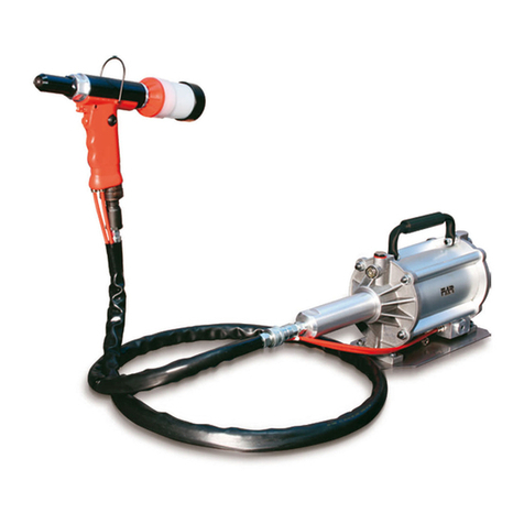
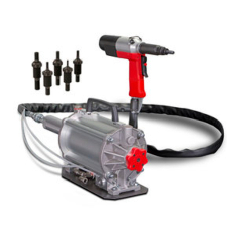
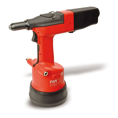
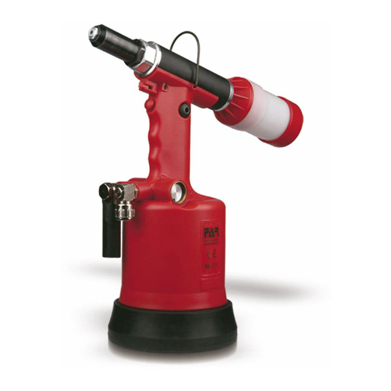
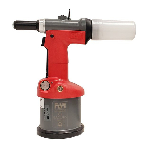
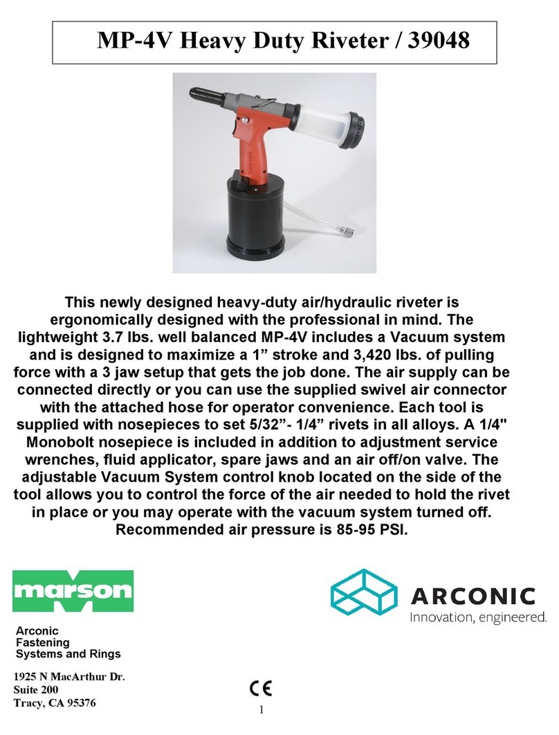
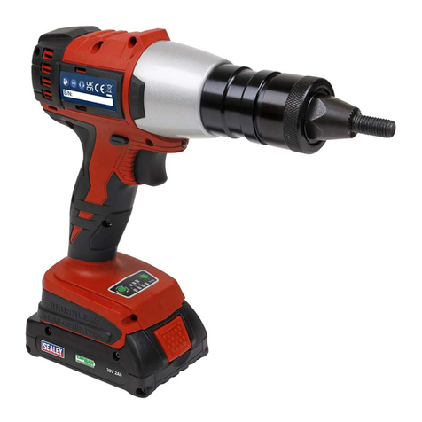
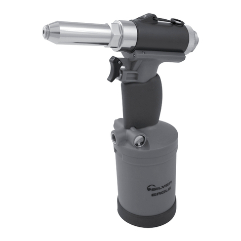
FAR KJ 70-A Setup guide

KJ 70-A
- ISTRUZIONI ORIGINALI
RIVETTATRICE OLEOPNEUMATICA
PER INSERTI 6-32 ÷ 1/2"-13
ISTRUZIONI D’USO - PARTI DI RICAMBIO
- TRANSLATION OF ORIGINAL INSTRUCTIONS
HYDROPNEUMATIC RIVETING TOOL
FOR INSERTS 6-32 ÷ 1/2"-13
INSTRUCTIONS FOR USE - SPARE PARTS
I
GB
KJ 70-A

KJ 70-A
Far S.r.l. - Massimo Generali
(Presidente del Consiglio di Amministrazione)
(Chairman of the Board of Directors)
(Président du Conseil d’Administration)
(Vorsitzender des Verwaltungsrates)
(Presidente del Consejo de Administración)
(Prezes Zarzadu)
.............................................
La sottoscritta Far S.r.l., con sede in Quarto Inferiore (BO) alla via Giovanni XXIII n° 2,
DICHIARA
sotto la propria esclusiva responsabilità che la rivettatrice
“KJ 70 Rivettatrice oleopneumatica per inserti filettati 6-32 ÷ 1/2"-13 con Booster di potenza separato dal corpo rivettatrice”
numero di serie: vedi retro copertina, alla quale questa dichiarazione si riferisce è conforme ai requisiti essenziali di sicurezza
previsti dal dal D. Lgs. 17/2010 di recepimento della Direttiva Macchine 2006/42/CE e successive modificazioni ed integrazioni.
La persona autorizzata a costituire il fascicolo tecnico risponde al nome di Massimo Generali, presso la Far S.r.l., con sede in
Quarto Inferiore (BO) alla via Giovanni XXIII n° 2.
The undersigned Far S.r.l., having its office in Quarto Inferiore (BO), Via Giovanni XXIII No. 2, herewith
DECLARES
on its sole responsability that the riveting machine
“KJ 70 Hydropneumatic tool for blind rivet nuts 6-32 ÷ 1/2"-13 Tool body separated from the intensifier” serial number: see back
cover, which is the object of this declaration complies with the basic safety requirements estabilished in the law decree Leg. D.
17/2010 of Machinery Directive 2006/42/CE acknowledge and subsequent amendments and integrations.
The person who is authorized to create the technical brochure is Massimo Generali, c/o Far S.r.l., head office in Quarto Inferiore
(BO), via Giovanni XXIII n. 2.
Quarto Inferiore, 01-03-2019
I
GB

I
I
ISTRUZIONI D’USO.................................................4
INSTRUCTIONS FOR USE.......................................9
PARTI DI RICAMBIO .............................................14
SPARE PARTS.......................................................16
KJ 70-A
GB
GB

I
4Date 04-2017 Revisione - 00
KJ 70-A
ISTRUZIONI D’USO
INDICE
GARANZIA E ASSISTENZA TECNICA.....................................4
AVVERTENZE E MISURE DI SICUREZZA...............................4
IDENTIFICAZIONE DELLA RIVETTATRICE .............................5
NOTE GENERALI E CAMPO DI APPLICAZIONE.....................5
PARTI PRINCIPALI................................................................5
DATI TECNICI........................................................................5
POSA IN OPERA DELL’INSERTO...........................................6
CAMBIO DI FORMATO ..........................................................7
RABBOCCO OLIO CIRCUITO OLEODINAMICO ......................8
SMALTIMENTO DELLA RIVETTATRICE .................................8
ATTENZIONE!!!
La mancata osservanza o trascuratezza delle seguenti
avvertenze di sicurezza può avere conseguenze sulla
vostra o altrui incolumità e sul buon funzionamento
dell’utensile.
•Leggereattentamenteleistruzioniprimadell’uso.
•Perleoperazionidimanutenzionee/oriparazioneaffidarsi
a centri di assistenza autorizzati dalla FAR s.r.l. e fare uso
esclusivo di pezzi di ricambio originali. La FAR s.r.l. declina
ogni responsabilità per danni da particolari difettosi, che
si dovessero verificare per inadempienza di quanto sopra
(Direttiva CEE 85/374).
L’ELENCO DEI CENTRI DI ASSISTENZA È DISPONIBILE SUL
NS. SITO WEB: http://www.far.bo.it ( Organizzazione )
•Siraccomandal’usodell’utensile dapartedipersonale
specializzato.
•Durantel’impiegodell’utensile, usareocchialiovisiere
protettive e guanti.
•Perleoperazionidicaricaolio,usaresolo fluidicon
caratteristiche indicate nel presente fascicolo.
•Incasodiperditeaccidentalidioliochedovesserovenire
a contatto con la pelle, lavarsi accuratamente con acqua e
sapone alcalino.
•L’utensilepuòesseretrasportatoamanoedèconsigliabile,
dopo l’uso, riporlo nel proprio imballo.
GARANZIA E ASSISTENZA TECNICA
Le rivettatrici FAR sono coperte da garanzia di 12 mesi.
Il periodo di garanzia dell'attrezzo decorre dal momento
della sua comprovata ricezione da parte dell'acquirente. La
garanzia copre l'utente/acquirente quando l'attrezzo viene
acquistatoattraversoun rivenditoreautorizzato esoloquando
viene impiegato per gli usi per i quali è stato concepito. La
garanzia non è valida se l'attrezzo non viene utilizzato e se
non viene sottoposto a manutenzione come specificato nel
manuale di istruzione e manutenzione. In caso di difetti o
guasti la FAR S.r.l. si impegna unicamente a riparare e/o
sostituire, a propria discrezione esclusiva, i componenti
giudicati difettosi.
AVVERTENZE E MISURE Dl SICUREZZA
•Si consigliaaifinidi uncorrettofunzionamentodella
rivettatrice, una revisione semestrale.
• Gliinterventidiriparazioneepuliziadell’utensiledovranno
essere eseguiti con macchina non alimentata dall’aria
compressa.
• Èconsigliabile,ove possibile,I’uso diunbilanciatore di
sicurezza.
• Incasodiesposizionequotidianapersonaleinambienteil
cui livello di pressione acustica dell’emissione ponderata
A sia superiore al limite di sicurezza di 70 dB (A), fare uso
di adeguati mezzi individuali di protezione dell’udito (cuffia
o tappo antirumore, diminuzione del tempo di esposizione
quotidiana etc...).
• Mantenereilbancoe/ol’areadilavoropulitaeordinata,il
disordine può causare danni alla persona.
• Nonlasciareche personeestranee allavoro tocchinogli
utensili.
• Assicurarsicheitubidialimentazionedell’ariacompressa
siano correttamente dimensionati per l’uso previsto.
• Nontrascinarel’utensilecollegatoall’alimentazionetirandolo
per il tubo; mantenere quest’ultimo lontano da fonti di calore
e da oggetti taglienti.
• Manteneregliutensili inbuono statod’usoe puliti,non
rimuovere mai le protezioni e il silenziatore dell’utensile.
•Dopo avereeseguitooperazionidiriparazione e/o
registrazione assicurarsi di avere rimosso le chiavi di servizio
o di registrazione.
•Primadiscollegareiltubodialimentazionedell’aria
compressa dalla rivettatrice, assicurarsi che quest’ultimo
non sia in pressione.
• Attenersiscrupolosamenteaquesteistruzioni.

5
I
Revisione - 00 Date 04-2017
KJ 70-A
IDENTIFICAZIONE DELLA RIVETTATRICE
La rivettatrice KJ 70-A è identificata da una marcatura indicante
ragione sociale e indirizzo, designazione della macchina ,
marcatura CE. In caso di richiesta di assistenza tecnica fare
sempre riferimento ai dati riportati nella marcatura.
NOTE GENERALI E CAMPO DI APPLICAZIONE
L’uso dell’utensile è finalizzato esclusivamente all’utilizzo di
inserti filettati con filetto compreso tra 6-32 e 1/2"-13.
Il sistema oleopneumatico utilizzato dalla rivettatrice KJ 70-A
fornisce una maggior potenza rispetto al tradizionale sistema
pneumatico su cui si basano altri modelli di rivettatrici. Ciò
significauna drastica riduzionedei problemidovuti all’usuradei
componenti con conseguente aumento di affidabilità e durata.
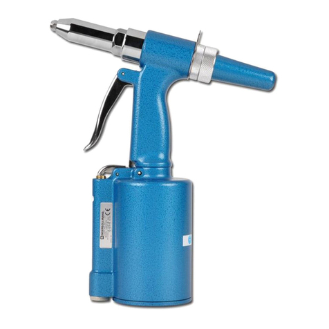
Le soluzioni tecniche adottate riducono le dimensioni e il peso
della macchina rendendo la rivettatrice KJ 70-A assolutamente
maneggevole. Lapossibilitàdi perdite dalsistemaoleodinamico
sonopreclusedall’impiego diguarnizionia tenutache eliminano
questo problema.
DATI TECNICI
• Pressionediesercizio ................................................6 BAR
• Diametrointernominimotuboalimentazione
aria compressa .......................................................... 8 mm
• Consumomaxarialibera,perciclo......................... 10,4 Nl
• Forzamassima......................................... 6 BAR - 30143 N
PESO:
• Pistola...................................................................2,050 Kg
• Totale ....................................................................6,850 Kg
• Temperaturadiutilizzo........................................-5°/+50 C°
• Valoremedioquadraticoponderatoin
frequenza dell’accelerazione complessiva (Ac)
a cui sono sottoposte gli arti superiori................ < 2,5 m/s2
• Pressioneacusticadell’emissioneponderata(A)..... 78 dBA
• Pressioneacusticaistantaneaponderata(C) ...... < 130 dBC
• Potenzaacusticaponderata(A) ............................... 90 dBA
PARTI PRINCIPALI
A)................................................. Ghiera bloccaggio testina
B).................. Foro inserimento spina sbloccaggio innesto
C)...........................................................Attacco bilanciatore
D).................................................. Ghiera regolazione corsa
E) ...........................................................Motore pneumatico
F) .................................................................. Tirante filettato
G)................................................................................Testina
H)............................ Grilletto di comando: pos.1 Trazione -
............................................................- pos.2 Svitamento
I).......................................... Allacciamento aria compressa
L) ...............................................................Tappo carico olio
M).............................................................. Tappo di servizio
N)......................................................Segnalatore livello olio
KJ 70-A
KJ 70-A
Ragione sociale e indirizzo
del fabbricante
Designazione
macchina
Numero di serie
KJ 70-A
150
315
165
Ø 25
90
350
Ø 44
265
A
I
M
NL
H
2
1
F
E
BCD
G
ALIMENTAZIONE DELL’ARIA
L’aria di alimentazione deve essere libera da corpi estranei e da
umidità per proteggere la macchina da usura precoce
delle parti in movimento; è consigliabile, pertanto, l’impiego di
un gruppo lubrificatore per aria compressa.

I
6Date 04-2017 Revisione - 00
KJ 70-A
ATTENZIONE!!! LA REGOLAZIONE NON CORRETTA DELLA CORSA DELLA RIVETTATRICE
PUÒ CAUSARE IL CATTIVO SERRAGGIO DEGLI INSERTI E LA ROTTURA DEL TIRANTE!
POSA IN OPERA DELL’INSERTO
Verificare che la coppia tirante-testina montata sulla rivettatrice sia adeguata alla misura dell’inserto che si vuole serrare; in caso
contrario procedere al cambio di formato. Solitamente la coppia tirante-testina montata sulla rivettatrice in confezione corrisponde
ad una filettatura di 3/8-16. Prima di utilizzare la rivettatrice e dopo ogni cambio di formato occorre eseguire le seguenti operazioni
in funzione del formato e dello spessore del materiale da serrare.
Inserire nelle tacche della ghiera di regolazione corsa I’apposita chiave (in dotazione). Regolare la corsa della rivettatrice al minimo,
ruotando per quanto possibile la ghiera “G” nel senso indicato dal simbolo “–”. Inserire l’inserto sul tirante ed esercitare su di esso
una leggera pressione; in questo modo l’inserto si avvita automaticamente sul tirante. Assicurarsi che la testa dell’inserto vada
in battuta con la testina della rivettatrice. Fissare l’inserto e verificare il serraggio che questo opera sullo spessore del materiale.
Regolare la corsa della rivettatrice mediante la rotazione della ghiera “G”, in funzione del serraggio desiderato, considerando che
all’aumentare della corsa (rotazione della ghiera “G” nel senso indicato dal simbolo “+”) la distanza “h” tra testa e deformazione
dell’inserto diminuisce con conseguente aumento dell’azione di serraggio.
+
–
H
H
G

7
I
Revisione - 00 Date 04-2017
KJ 70-A
CAMBIO DI FORMATO
Al variare della filettatura degli inserti da serrare, occorre eseguire la sostituzione della coppia Tirante/testina, pertanto procedere
come segue:
FIG. 1. Allentare la ghiera con una chiave commerciale di mm 22 e rimuovere la testina.
FIG. 2. Fare passare la spina (in dotazione) attraverso l’apposito foro di servizio,situato nel canotto porta testina, ed esercitare
su di essa una pressione verso l’interno in modo da sbloccare l’innesto dal tirante. Contemporaneamente svitare il tirante ed
estrarlo leggermente.
FIG. 3-4. Mantenendo sbloccato l’innesto avvitare il formato di tirante desiderato. Completata la sostituzione del Tirante ruotarlo
leggermente fino a che non si avverte lo scatto d’innesto, procedere quindi al montaggio della relativa testina bloccandola con
l’apposita ghiera allentata in precedenza. Ogni volta che si effettua il cambio di formato ripetere le operazioni di registrazione
riportate nelle pagine precedenti.
ATTENZIONE! LE OPERAZIONI SOPRAELENCATE DEVONO ESSERE ESEGUITE CON MACCHINA NON ALIMENTATA.
22 mm.
22 mm.
1 2
34

I
8
KJ 70-A
Date 04-2017 Revisione - 00
ATTENZIONE! Prima di scollegare il tubo dell’aria compressa dalla rivettatrice accertarsi che quest’ultimo non
sia in pressione! Si raccomanda l’uso di olio HLP 32 cSt o simili.
SMALTIMENTO DELLA RIVETTATRICE
Per lo smaltimento della rivettatrice attenersi alle prescrizioni imposte dalle leggi nazionali.
Dopo aver scollegato la macchina dall’impianto pneumatico, procedere allo smontaggio dei vari componenti
suddividendoli in funzione della loro tipologia: acciaio, alluminio, materiale plastico, ecc.
Procedere quindi alla rottamazione nel rispetto delle leggi vigenti.
RABBOCCO OLIO CIRCUITO OLEODINAMICO
Verificare periodicamente che il livello dell’olio non scenda mai al di sotto dei 3/4 indicati dall’apposito segnalatore (B). Nel caso si rendesse
necessario un rabbocco togliere il tappo (A) servendosi di una chiave di mm 17, quindi immettere olio idraulico HLP 32 cSt finché questo non
raggiunge il bordo del foro filettato.
ATTENZIONE ! Nel caso questa operazione non venga effettuata, si potrà riscontrare, nel tempo, un calo di corsa della rivettatrice che andrà
accentuandosi fino a comprometterne il funzionamento. Occorrerà pertanto eliminare la presenza d’aria all’interno del circuito oleodinamico e
ripristinarne la corretta quantità di olio. Procedere quindi come segue: Riporre il corpo rivettatrice all’interno di un raccoglitore (in modo da non
disperdere eventuali fuoriuscite di olio) e posizionare la parte superiore del booster in modo tale che si trovi esattamente sullo stesso piano
del corpo rivettatrice, mentre i tubi di alimentazione devono essere disposti come da figura. Rimuovere il tappo di rabbocco olio (A) e il tappo
di servizio (C) servendosi rispettivamente di una chiave commerciale di mm. 17 e di una chiave commerciale a brugola di mm.5. Immettere olio
idraulico HLP 32 cSt fino a che questo non uscirà privo di tracce di aria (bolle) dal foro liberato dal tappo di servizio (C). Ad operazione ultimata
rimontare il tappo di servizio (C) e verificare che l’olio abbia raggiunto il bordo del foro filettato, rimontare quindi il tappo (A) e pulire accuratamente
larivettatricedall’oliofuoriuscito.Èestremamenteimportanteattenersialleistruzionisopraindicateedeffettuareleoperazionidirabboccoolio
muniti di guanti.L’olio fuoriuscito durante le operazioni indicate, dovrà essere raccolto in appositi recipienti ed affidato successivamente ad una
ditta autorizzata per lo smaltimento del rifiuto. Non schiacciare o tagliare i tubi che collegano la rivettatrice al booster.
Ach.17mm
IMPORTANTE: Assicurarsi che il tappo di rabbocco
olio (G) venga serrato con una coppia pari a:
min. 5 Nm ÷ Max. 8 Nm.
min. 5 Nm
Max. 8 Nm
C
B
KJ
70-A
KJ 70-A

9
GB
KJ 70-A
Revisione - 00 Date 04-2017
INSTRUCTIONS FOR USE I
INDEX
GUARANTEE AND TECHNICAL ASSISTANCE.............................. 9
SAFETY MEASURES AND REQUIREMENTS ............................... 9
TOOL IDENTIFICATION ............................................................. 10
GENERAL NOTES AND USE ...................................................... 10
MAIN COMPONENTS ................................................................ 10
TECHNICAL DATA ..................................................................... 10
PLACING OF THE INSERT......................................................... 11
CHANGE OF SIZE ..................................................................... 12
TOOPING UP THE OIL-DYNAMIC CIRCUIT ............................... 13
DISPOSAL OF THE RIVETING TOOL ......................................... 13
CAUTION!!!
All the operations must be done in conformity with the
safety requirements, in order to avoid any consequence
for your and other people security and to allow the best
tool work way.
•Readtheinstructionscarefullybeforeusingthetool.
•Forall maintenance and/orrepairspleasecontact FAR
s.r.l. authorized service centers and use only original
spare parts. FAR s.r.l. may not be held liable for
damages from defective parts caused by failure to
observe what mentioned above (EEC directive
85/374).
The list of the service centres is available on our website
http://www.far.bo.it ( Organization )
•Thetoolmustbeusedonlybyexpertworkers.
•Aprotectivevisorandglovesmustbeputonwhenusing
the tool.
•Fortoppingupthe oil,wesuggestusingonly fluidsin
accordance with the features specified in this working book.
•Ifanydropofoiltouchesyourskin,youmustwashwith
water and alkaline soap.
•Thetoolcanbecarriedandwesuggestputtingitintoitsbox
after using.
GUARANTEE AND TECHNICAL ASSISTANCE
FAR riveting tools are covered by a 12-month warranty. The
tool warranty period starts on the date of delivery to the
buyer, as specified in the relevant document. The warranty
covers the user/buyer provided that the tool is purchased
through an authorized dealer and only if it is used for the
purposes for which it was conceived. The warranty shall
not be valid if the tool is not used or maintained as specified
in the instruction and maintenance handbook. In the event
of defects or failures, FAR S.r.l. shall undertake solely to
repair and/or replace the components it judges to be faulty.
SAFETY MEASURES AND REQUIREMENTS
• Thetoolneedsathoroughsix-monthlyoverhaul.
• Repairingandcleaningoperationsmustbedonewhenthe
tool is not fed.
• Asafetybalancerissuggestedwhenitispossible.
• IftheA-weightedemissionsoundpressurelevelismorethan
70 dB (A), you must use some hearing protections (anti-noise
headset, etc.).
• Theworkbenchandtheworksurfacemustbealwaysclean
and tidy. The untidy can cause damages to people.
• Donotallowunauthorizedpersonstousetheworkingtools.
• Makeyousurethatthecompressedairfeedinghoseshave
the correct size to be used.
• Donotcarrytheconnectedtoolbypullingthehose.Thehole
must be far from any heating sources or from cutting parts.
• Keepthetoolsingoodconditions;donotremoveeithersafety
parts or silencers.
• Afterrepairingand/oradjusting,makesureyouhavealready
removed the adjusting spanners.
• Beforedisconnectingthecompressedairhosefromthetool
make sure that there is no pressure in the hose.
• Theseinstructionsmustbecarefullyfollowed.

GB
10 Date 04-2017 Revisione - 00
KJ 70-A
TOOL IDENTIFICATION
The riveting tool KJ70-Aisidentified fromamarking thatshows
company name and address of manufacturer, designation of
the tool, CE. Always refer to the information on the riveting tool
when requesting technical service.
GENERAL NOTES AND USE
The tool can be employed only for blind rivet nuts with thread
of 6-32 e 1/2"-13 diameter.
The KJ 70-A oil pneumatic system assures more power than
the pneumatic system used for other models. That means
a reduction in the problems due to the wear and tear of the
components, therefore, there will be an increase in reliability.
The technicai solutions adopted reduce the dimensions and the
weight of the tooi which, for these reasons, make it very handy.
The possibilities of leakage from the oil-dynamic system, are
eliminated by some sealed gaskets, which solve this problem.
TECHNICAL DATA
• Workingpressure ......................................................87 psi
• Min.int.diam.ofthecompressedair
feeding hose ...........................................................0.315"
• Airconsumptionpercycle ........................................6.3 in³
• Maxpower................................................ 87 psi - 3070 lbf
WEIGHT:
• Gun.......................................................................... 4.52 lb
• Total............................................................................ 15 lb
• Workingtemperature.....................................-23°F/+122°F
• Rootmeansquareintotalaccelerationfrequency(Ac)
to which the arms are subjected...................... < 98.42 ips²
• A-weightedemissionsoundpressurelevel............. 78 dBA
• PeakC-weightedinstantaneoussoundpressure<130 dBC
• A-weightedsoundpower........................................ 90 dBA
MAIN COMPONENTS
A) ..................................................... Ring nut clamping head
B) ................................ Insertion Pin Hole Dechucking clutch
C) ...........................................................Balancer connection
D) ................................................Ring nut adjustment stroke
E) ............................................................... Pneumatic motor
F) .................................................................Threaded tie rod
G) ...................................................................................Head
H)........... Drive trigger: Pos. 1 Tiraction - Pos. 2 Unscrewing
I) ................................................... Compressed air connection
L) .......................................................................Oil filler plug
M) ......................................................................Service plug
N)................................................................ Oil level indicator
KJ 70-A
KJ 70-A
KJ 70-A
5.9”
12.5”
6.5”
Ø
1”
3.5”
13.8”
Ø
1.7”
10.4”
A
I
M
NL
H
2
1
F
E
BCD
G
AIR FEED
The air feed must be free from foreign bodies and humidity in
order to protect the tool from premature wear and tear
of the components in movement, therefore we suggest to use
a lubrificator group for compressed air.
Company name and
address
Designation of
the tool
Serial number

11
GB
Revisione - 00 Date 04-2017
KJ 70-A
WARNING!!! A WRONG ADJUSTMENT OF THE RIVETING TOOL STROKE
MAY CAUSE A FAULTY CLAMPING OF INSERTS AND MAY BRAKE THE TIE ROD!
PLACING OF THE INSERT
Make sure that the couple tie-rod/head mounted on your riveting tool is suitable for the insert to clamp; otherwise, change size
accordingly. Usually the riveting tool is supplied with the couple tie-rod/head corresponding to a 3/8-16 thread. Before using
the riveting tool and after any change of size, perform the following operations according to the size and thickness of the part to
clamp. Plug in the notchs of the regulation stroke ring nut the special key (issued). Adjust the riveting tool stroke to the minimum
by turning the ring nut “G” to “–” marked on the tool. Place the insert on the tie rod and push slightly on it so as to make it clamp
automatically. Make sure the insert head touches the riveting tool head properly. Fasten the insert and in order to ensure a proper
clamping of the material, adjust the riveting tool stroke by turning the ring nut “G” accordingly. By increasing stroke, i.e. by turning
the ring nut “G” to “+”, the distance “h” between head and insert deformation will decrease and clamping will result more effective.
+
–
H
H
G

GB
12 Date 04-2017 Revisione - 00
KJ 70-A
CHANGE OF SIZE
Depending on insert thread, it is necessary to replace the couple “tie-rod/head” as follows:
PICTURE 1. Loosen the ring nut by means of a 22-mm standard spanner and remove the riveting tool head.
PICTURE 2. Make the pin supplied pass through the pertinent service hole located on the cone carrying head and apply a light
pressureontheheadinwards,inordertodechuckthetierodclutch.,atthesametime,unscrewthetierodandextractit.
PICTURE 3-4.Keeptheclutchdechuckedandscrewthetierodsizedesired.Whenthereplacementofthetierodhasbeen
performed, swing it until you hear a click. Them assembly the proper head and lock it with the corresponding ring nut loosen
before. Each time you carry out any change of size, repeat the adjustment operations as specified in the previous pages.
WARNING! DESCONNECT AIR FEED WHEN PERFORMING THOSE OPERATIONS.
22 mm.
22 mm.
1 2
34

13
GB
Revisione - 00 Date 04-2017
KJ 70-A
TOPPING UP THE OIL-DYNAMIC CIRCUIT
Verify periodically that the oil level does not go below 3/4 of the limit indicated by the proper indicator (
B
).Whetheryouneedtotopup
the circuit, remove the plug (
A
) by means of a 17-mm wrench, then pour hydraulic oil,
HLP 32 cSt
, until it reaches the border of the
threaded hole.
WARNING!
If you fail to perform this operation, you will note power loss that will lead to jeopardise the proper working of the tool.
Therefore,youneedtogetridoftheairfromthetoolandrestoretheexactoillevelintheoil-dynamiccircuit.
Proceed as follows: put the riveting gun inside a container, in order to avoid loosing oil, and put the upper side of the booster on the same
level of the gun/and lay the feed hoses as the picture shows. Remove the oil screw cap (
A
) and the service plug (
C
) by using a 17-mm
wrench and a 5-mm allen wrench respectively. Pour oil
HLP 32 cSt
until it flows from the hole, without plug (
C
), completely free from
airbubbles.Whentheoperationhasbeencarriedout,replacetheplug(
C
) and make sure that oil has reached the border of the threaded
hole. Screw the screw cap (
A
) and clean carefully the riveting tool from overflowed oil. It is very important to apply carefully to the
instructions and use always gloves when you handle the tool. Overflowed oil, during the topping, must be collected in proper containers
and delivered afterwards, to specialized waste oil getthering company. Do not smash or cut the connecting hoses between gun and booster.
WARNING! Before disconnecting the compressed air hose, make sure that it is not under pressure!
We recommend to use oil HLP 32 cSt or similars.
DISPOSAL OF THE RIVETING TOOL
Follow the prescriptions of the national laws for disposing of the riveting tool.
After disconnecting the tool from the pneumatic system, disassemble and split all the components according
to the material: steel, aluminium, plastic material, etc.
Then proceed to scrap the materials in accordance with current laws.
Ach.17mm
WARNING: Make sure that the oil filler cap
(A) is tightened at a torque corresponding to
min. 3.69 ÷ Max. 5.90 ftlb.
min. 3.69 ftlb
Max. 5.90 ftlb
C
B
KJ 70-A
KJ
70-A

I
14 Date 04-2017 Revisione - 00
KJ 70-A
PARTI DI RICAMBIO
Tav. 1/3 Tav. 1/3
N° COD. Qt. DESCRIZIONE KIT N° COD. Qt. DESCRIZIONE KIT
68
711106 2 Testina 10-24 UNC 10-32 UNF
69 711107 1 Testina 1/4"-20 UNC 1/4-28 UNF
70 711108 1 Testina 5/16"-18 UNC 5/16"-24 UNF
71 711110 1 Testina 1/2"-13 UNC
72 710873 1 Gancio bilanciatore
73 711092 1 Chiave a brugola 5 mm
74 710969 1 Contenitore olio
75 710970 1 Chiave regolazione corsa
76 710876 1 Spina disinnesto tirante
77 711348 1
Vite TCCE M4 x 16 UNI 5931
78 711135 1 Protezione motorino
83 722118 2 Cannotto guida tubo
85 712120 1 Innesto maschio
86 712044 1 Anello Parbak 8-217
87 711595 1 Tirante 10-32 UNF
KIT
N° COD. Qt. DESCRIZIONE
KITA 740879 Kit Innesto tirante
20A 710879 1 Innesto per tirante
21A 710138 1 Spinaelasticaø4x16UNI6873
22A 710874 1 Molla disinnesto tirante
KITB 740861 Kit Pulsante
38B 710885 1 Perno
39B 710861 1 Pulsante
KIT Indica che il particolare viene venduto in Kit composti da
particolari diversi in quantità diverse.
01 712151 1 Guarnizione B-141110 / NEO
03 710833 1 Pistone oleodinamico
04 710883 1 Innesto femmina
07 710875 1 Molla ritorno pistone
08 710869 1 Raccordo regolazione corsa
09 710925 1 Guarnizione OR 027
10 710863 1 Cannotto convogliatore aria
11 712122 1 Motore pneumatico SP-326
12 721496 2 Raccordo
13 710862 2
Tubo Rilsan ø 5 x 3,5
14 711600 1 Tirante 3/8-16 UNC
15 711109 1 Testina 3/8-16 UNC 3/8-24 UNF
16 710884 1 Ghiera
17 710880 1 Cannotto porta testina
18 710878 1 Raccordo anteriore
19 710881 1 Cannotto porta tirante
20A 710879 1 Innesto per tirante A
21A 710138 1 Spina elastica ø 4 x 16 UNI 6873 A
22A 710874 1 Molla disinnesto tirante A
23 710912 1 Dado M 10 x 6
24 710877 1 Bussola per guarnizione
25 710578 1 Guarnizione OR 2-217
26 710577 1 Guarnizione B-086055
27 710908 1 Rondella
28 711974 1 Anello Seeger JV 22
29 711083 1 Cilindro Oleodinamico
30 710866 2 Pulsante valvolina
31 710919 2 Guarnizione OR 2-004
32 710868 1 Corpo valvolina lunga
33 710847 1 Corpo valvolina
34 710528 2 Guarnizione OR 008
35 710867 1 Pistoncino valvola lungo
36 711150 1 Pistone valvolina
37 710918 2 Guarnizione OR 2-005
38B 710885 1 Perno B
39B 710861 1 Pulsante B
41 710376 2 Guarnizione OR 2-009
43 710906 1 Rondella 400-020-4490
44 710839 1 Tappo serbatoio olio
45 720813 1 Impugnatura
46 710385 2 Guarnizione OR 2-006
47 711035 1 Rondella
48 710931 1 Guarnizione OR 614
49 711037 1 Raccordo
50 711039 1 Raccordo girevole
51 711061 3 Guarnizione OR 5-614
52 711038 1 Raccordo sso
53 710921 1 Guarnizione OR 2-115
54 711036 1 Riduzione
55 711073 1 Tubo alta pressione mt 1,8
57 711084 2 Raccordo 6700 - ø 5
58 711059 2 Tubo Rilsan ø 5 x 3,5 x 2600
59 711031 1 Raccordo nale impugnatura
60 711592 1 Tirante 6-32 UNC
61 711593 1 Tirante 8-32 UNC
62 711594 1 Tirante 10-24 UNC
63 711596 1 Tirante 1/4"-20 UNC
64 711598 1 Tirante 5/16"-18 UNC
65
711602 1 Tirante 1/2"-13 UNC
66
711156 1 Testina 6-32 UNC
67
711105 1 Testina 8-32 UNC

15
I
Revisione - 00 Date 04-2017
KJ 70-A
Tav. 2/3
PARTI DI RICAMBIO
Tav. 3/3
N° COD. Qt. DESCRIZIONE
01
711218 1 Asta
02
711529 1 Ghiera
03
712124 1 Portasatelliti estremo
04
710949 1 Dado
05
710947 1 Cuscinetto 608-2Z
06
712123 3 Satellite
07
711477 1 Corona
08
711530 1 Distanziale
09
711531 1 Corpo esterno
10
710037 1 Cuscinetto 609-2Z
11
711524 1 Piattello anteriore
12
711474 6 Aletta
13
712125 1 Rotore
14
711476 1 Statore
15
711525 1 Piattello posteriore
16
710071 1 Cuscinetto 625-2Z
17
710944 1 Perno
18
721496 2 Raccordo
19
711532 1 Vite STCE M5 x 5 UNI 5923
20
710772 1 Guarnizione OR 2-007
21
711235 1 Sfera ø 7
22
711473 1 Molla
23
711498 1 Tappo
24
711485 1 Deettore
A
712122 Motore pneumatico SP-326
N° COD. Qt. DESCRIZIONE KIT
01 711824 1 Raccordo NV 1/4" NPT-M
02 711823 1 Raccordo NV 1/4" NPT-F
03 711825 1 Raccordo NPT 1300
04 711662 1 Livello olio HFE.9
05 710375 2 Guarnizione OR 2-131
06 711660 1 Tappo
07 711663 1 Tappo 2611-1/4"
08 710211 6 Vite TCCE M6 x 14 UNI 5931
09 711656 1 Testata cilindro
10 711664 1 Guarnizione OR 2-237
11 711658 1 Cannotto Booster
13 711053 1 Anello di arresto guarnizione
14 711066 1 Anello Sealing RSS 12-20
15 711050 1 Bussola per guarnizione
16C 710572 1 Guarnizione OR 2-120 C
17C 711661 1 Guarnizione OR 2-135 C
18C 711065 1 Anello Sealing WRI 12 C
19 711827 1 Guarnizione TS-12-19-5,7 / L
20 711657 1 Guida stelo
21 710931 1 Guarnizione OR 614
22D 710829 1 Ammortizzatore D
23 711659 1 Stelo
24D 710923 1 Guarnizione OR 012 D
25 711678 1 Pistone pneumatico
26D 710912 1 Dado M 10 x 6 D
27 711679 1 Guarnizione OR 2-339
28 711655 1 Cilindro
29E 711829 2 Vite TSCE M6 x 20 UNI 5933 E
30 711828 1 Piede
31E 710623 2 Dado M 6 UNI 7473 E
32 710173 1 Raccordo dado fresato 1/4"
33 712061 1 Rondella
34F 710840 1 Distanziale valvola F
35F 710921 3 Guarnizione OR 2-115 F
36F 710823 3 Gabbia F
37F 711158 1 Molla ritorno spoletta F
38 710841 1 Spoletta
39 710916 1 Guarnizione OR 2-015
40 710528 1 Guarnizione OR 008
41 710822 1 Pistoncino valvola
42 710258 1 Guarnizione OR 5-612
43 710905 1 Anello Seeger 11 UNI 7437
44 710922 2 Guarnizione OR 018
45 712268 1 Tappo guida molla
46 711665 1 Tappo valvola
47 711085 1 Silenziatore SPL 3 / 8"
48 711068 2 Raccordo 6520 - ø 5 - 1/8"
49 711826 1 Raccordo 2020 - 1/4"
50 711121 1 Riduzione 2521-1/4"-3/8"
51 712160 1 Guaina contenimento tubi
52 712050 1 Vite STCE M8 x 8 UNI 5923
Tav. 2/3
KIT
N° COD. Qt. DESCRIZIONE
KITC 741065 Kit Guarnizioni
16C
710572 1 Guarnizione OR 2-120
17C
711661 1 Guarnizione OR 2-135
18C
711065 1 AnelloSealingWRI12
KITD 740829 Kit Ammortizzatore
22D
710829 1 Ammortizzatore
24D
710923 1 Guarnizione OR 012
26D
710912 1 DadoM10x6
KITE 741829 Kit Vite M 6
29E
711829 5 ViteTSCEM6x20UNI5933
31E
710623 5 Dado M 6 UNI 7473
KITF 740840 Kit Distanziale valvola
34F
710840 1 Distanziale valvola
35F
710921 3 Guarnizione OR 2-115
36F
710823 3 Gabbia
37F
711158 1 Molla ritorno spoletta
KIT Indica che il particolare viene venduto in Kit composti da
particolari diversi in quantità diverse.

GB
16 Date 04-2017 Revisione - 00
KJ 70-A
SPARE PARTS
Tab. 1/3 Tab. 1/3
No. CODE Q.ty DESCRIPTION KIT No. CODE Q.ty DESCRIPTION KIT
68
711106
2
Head 10-24 UNC 10-32 UNF
69 711107 1 Head 1/4"-20 UNC 1/4-28 UNF
70 711108 1 Head 5/16"-18 UNC 5/16-24 UNF
71 711110 1 Head 1/2"-13 UNC
72 710873 1 Balancer hook
73 711092 1 Wrench 5 mm
74 710969 1 Oil container
75 710970 1 Stroke adjusting nut
76 710876 1 Tie rod release pin
77 711348 1
Screw TCCE M4 x 16 UNI 5931
78 711135 1 Fender motor
83 722118 2 Guide tube sleeve
85 712120 1 Male clutch
86 712044 1 Ring Parbak 8-217
87 711595 1 Head 10-32 UNF
KIT
No. CODE Q.ty DESCRIPTION
KITA 740879 Tie rod clutch kit
20A 710879 1 Tie rod clutch
21A 710138 1 Springpinø4x16UNI6873
22A 710874 1 Disengagement tie rod spring
KITB 740861 Push-button kit
38B 710885 1 Roll pin
39B 710861 1 Push-button
KIT It indicates that the part is sold in kits consisting of different
parts in different quantities.
01 712151 1 Gasket B-141110 / NEO
03 710833 1 Oil-dynamic piston
04 710883 1 Female clutch
07 710875 1 Piston return spring
08 710869 1 Adjustement stroke connector
09 710925 1 Gasket OR 027
10 710863 1 Air conveyor sleeve
11 712122 1 Pneumatic Motor SP-326
12 721496 2 Connector
13 710862 2
Rilsan tube ø 5 x 3,5
14 711600 1 Tie rod 3/8-16 UNC
15 711109 1 Head 3/8-16 UNC 3/8-24 UNF
16 710884 1 Ring nut
17 710880 1 Sleeve carrying head
18 710878 1 Front connector
19 710881 1 Sleeve carrying tie rod
20A 710879 1 Tie rod clutch A
21A 710138 1 Spring pin ø 4 x 16 UNI 6873 A
22A 710874 1 Disengagement tie rod spring A
23 710912 1 Nut M 10 x 6
24 710877 1 Sleeving gasket
25 710578 1 Gasket OR 2-217
26 710577 1 Gasket B-086055
27 710908 1 Washer
28 711974 1 Seeger ring JV 22
29 711083 1 Oil-dynamic cylinder
30 710866 2 Push-button
31 710919 2 Gasket OR 2-004
32 710868 1 Long valve body
33 710847 1 Valve body
34 710528 2 Gasket OR 008
35 710867 1 Long valve piston
36 711150 1 Valve piston
37 710918 2 Gasket OR 2-005
38B 710885 1 Roll pin B
39B 710861 1 Push-button B
41 710376 2 Gasket OR 2-009
43 710906 1 Washer 400-020-4490
44 710839 1 Oil tank plug
45 720813 1 Handgrip
46 710385 2 Gasket OR 2-006
47 711035 1 Washer
48 710931 1 Gasket OR 614
49 711037 1 Connector
50 711039 1 Rotating connector
51 711061 3 Gasket OR 5-614
52 711038 1 Fixed connector
53 710921 1 Gasket OR 2-115
54 711036 1 Reduction
55 711073 1 High pressure tube mt 1,8
57 711084 2 Connector 6700 - ø 5
58 711059 2 Rilsan tube ø 5 x 3,5 x 2600
59 711031 1 Ending handgrip connector
60 711592 1 Tie rod 6-32 UNC
61 711593 1 Tie rod 8-32 UNC
62 711594 1 Tie rod 10-24 UNC
63 711596 1 Tie rod 1/4"-20 UNC
64 711598 1 Tie rod 5/16"-18 UNC
65 711602 1 Tie rod 1/2"-13 UNC
66 711156 1 Head 6-32 UNC
67 711105 1 Head 8-32 UNC

17
GB
Revisione - 00 Date 04-2017
KJ 70-A
SPARE PARTS
Tab. 2/3
No. CODE Q.ty DESCRIPTION KIT
01 711824 1 Connector NV 1/4" NPT-M
02 711823 1 Connector NV 1/4" NPT-F
03 711825 1 Connector NPT 1300
04 711662 1 Oil level HFE.9
05 710375 2 Gasket OR 2-131
06 711660 1 Cap
07 711663 1 Cap 2611-1/4"
08 710211 6 Screw TCCE M6 x 14 UNI 5931
09 711656 1 Cylinder head
10 711664 1 Gasket OR 2-237
11 711658 1 Booster sleeve
13 711053 1 Stop ring
14 711066 1 Ring Sealing RSS 12-20
15 711050 1 Sleeving gasket
16C 710572 1 Gasket OR 2-120 C
17C 711661 1 Gasket OR 2-135 C
18C 711065 1 Ring Sealing WRI 12 C
19 711827 1 Gasket TTS-12-19-5,7 / L
20 711657 1 Steam guide
21 710931 1 Gasket OR 614
22D 710829 1 Shock absorber D
23 711659 1 Steam
24D 710923 1 Gasket OR 012 D
25 711678 1 Pneumatic piston
26D 710912 1 Nut M 10 x 6 D
27 711679 1 Gasket OR 2-339
28 711655 1 Cylinder
29E 711829 2 Screw TSCE M6 x 20 UNI 5933 E
30 711828 1 Foot
31E 710623 2 Nut M 6 UNI 7473 E
32 710173 1 Milled nut connector 1/4"
33 712061 1 Washer
34F 710840 1 Valve spacer F
35F 710921 3 Gasket OR 2-115 F
36F 710823 3 Cage F
37F 711158 1 Coil return spring F
38 710841 1 Coil
39 710916 1 Gasket OR 2-015
40 710528 1 Gasket OR 008
41 710822 1 Valve piston
42 710258 1 Gasket OR 5-612
43 710905 1 Seeger ring 11 UNI 7437
44 710922 2 Gasket OR 018
45 712268 1 Spring guide plug
46 711665 1 Valve cap
47 711085 1 Silencer SPL 3 / 8"
48 711068 2 Connector 6520 - ø 5 - 1/8"
49 711826 1 Connector 2020 - 1/4"
50 711121 1 Reduction 2521-1/4"-3/8"
51 712160 1 Sheath
52 712050 1 Dowel STCE M8 x 8 UNI 5923
Tab. 3/3
No. CODE Q.ty DESCRIPTION
01
711218 1 Rod
02
711529 1 Ring nut
03
712124 1 Gear cage
04
710949 1 Nut
05
710947 1 Bearing 608-2Z
06
712123 3 Planetary gear
07
711477 1 Crown gear
08
711530 1 Spacer
09
711531 1 Outside body
10
710037 1 Bearing 609-2Z
11
711524 1 Front cap
12
711474 6 Vane
13
712125 1 Rotor
14
711476 1 Stator
15
711525 1 Back cap
16
710071 1 Bearing 625-2Z
17
710944 1 Roll pin
18
721496 2 Connector
19
711532 1 Screw STCE M5 x 5 UNI 5923
20
710772 1 Gasket OR 2-007
21
711235 1 Ball ø 7
22
711473 1 Spring
23
711498 1 Cap
24
711485 1 Bafe
A
712122 Pneumatic Motor SP-326
Tab. 2/3
KIT
No. CODE Q.ty DESCRIPTION
KITC 741065 Gasket Kit
16C
710572 1 Gasket OR 2-120
17C
711661 1 Gasket OR 2-135
18C
711065 1 RingSealingWRI12
KITD 740829 Dampener kit
22D
710829 1 Shock absorber
24D
710923 1 Gasket OR 012
26D
710912 1 NutM10x6
KITE 741829 Screw M 6 kit
29E
711829 5 ScrewTSCEM6x20UNI5933
31E
710623 5 Nut M 6 UNI 7473
KITF 740840 Valve spacer kit
34F
710840 1 Valve spacer
35F
710921 3 Gasket OR 2-115
36F
710823 3 Cage
37F
711158 1 Coil return spring
KIT
It indicates that the part is sold in kits consisting of different
parts in different quantities.

18
PARTI DI RICAMBIO • SPARE PARTS
KJ 70-A
Date 04-2017 Revisione - 00
Tav.1/3•Tab.1/3
60
15
67
68
69
70
71
66
16 17 18 19 20 A
21 A
1
72
3485 78910
12
11
30 31
37363433
22 A 23 24 25 26
83
83
A
A
B
B
27
38 B
39 B
28
29
78 77
30 31
3735
73
44
43
59
46
45
34
32
74 75 76
13
14
61
62
63
64
65
47
48
49
50
51
52
53
54
55
57
58
57
58
ABC
KIT A
KIT B
20A(x1)
21A(x1)
22A(x1)
38B(x1)
39B(x1)
41
41
86
mt 1,8
TAV. 2
68
87

19
PARTI DI RICAMBIO • SPARE PARTS
KJ 70-A
Revisione - 00 Date 04-2017
1
11
5
13
14
15
16 C
17 C
21
22 D
23
25
26 D
27
28
18 C
19
20
2
3
8
9
10
4
5
6
7
24 D
29 E
33
34 F
35 F
30
31 E
32
36 F
35 F
36 F
35 F
36 F
37 F
38
40
41
39
42
43
44
45
44
46
KIT C
KIT D KIT E KIT F
16C(x1)
17C(x1)
18C(x1)
22D(x1)
26D(x1)
24D(x1)
29E(x5)
31E(x5)
34F(x1)
35F(x3)
36F(x3)
37F(x1)
TAV. 1
50
47
49
48
51
48
B
A
C
52
KJ 70-A
Tav.2/3•Tab.2/3

20
PARTI DI RICAMBIO • SPARE PARTS
KJ 70-A
Date 04-2017 Revisione - 00
1
13
9
18
19
20 21 22
24
23
12
14
17
15
16
2
4
5
3
6
7
8
10
11
Tav.3/3•Tab.3/3
Table of contents
Languages:
Other FAR Rivet Tools manuals