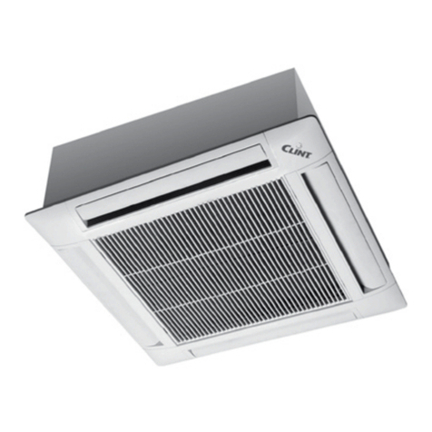
Clint TCW 42 Service manual

Manual de instalare, utilizare si intretinere • Casete
Installation, use and maintenance manual • Cassette
TCW
Serie / Series
TCW 42÷104
Editie / Edition Inlocuieste / Supersedes
04.06 ---
Catalog /
Catalogue
CLM 28
Produsele Clintsunt distribuite de:
031.100.66.66
[email protected] www.climatico.ro

MODEL MODEL 42 44 54 84 104
Debit de aer: Air flow: max m³/h 700 700 760 1550 1725
med m³/h 460 460 515 1350 1360
min m³/h 420 420 460 1100 1075
Nivel de zgomot (1): Sound pressure (1): max dB(A) 39 39 44 48 48
med dB(A) 27 27 36 40 41
min dB(A) 24 24 31 37 36
Alimentare electrica: Power supply: V/Ph/Hz <---------------230 / 1 / 50 ---------------->
Putere absorbita: Absorbed power: max kW 0,06 0,08 0,11 0,20 0,22
Alimentare baterie electrica: Electrical heater power supply: V/Ph/Hz <---------------230 / 1 / 50 ---------------->
Putere absorb. baterie electrica: Electric heater absorbed power: kW 1,5 2,3 2,6 4,3 5,2
Racorduri hidraulice pt. 2 si 4 tevi: Water connections for 2 and 4 pipes: ”G 1/2” 1/2” 3/4” 1” 1”
Masa: Weight: Kg 26 26 30 49 55
Performante / Performances
Dimensiuni, caracteristici tehnice si componente / Dimensions, technical characteristics and components
(1)
La distanta de 1 m si timp de reverberatie de 0,5 s.
Presiune maxima de functionare 1000 kPa.
Temperatura maxima apa la introducere 90 °C.
Poate fi adaugat aditional etilen glycol in apa.
(1)
At a distance of 1 m and with reverberation time of 0.5 s.
Maximum operating temperature 1000 kPa.
Maximum inlet water temperature 90 °C.
Inhibited ethylene glycol can be added to the water.
1.1 Dimensiuni modele 42 ÷ 54 / Models 42 ÷ 54 dimensions
Casete cu 2 si 4 tevi / 2 and 4 pipes Cassette
3
4
9
8
7
12
11 2
6
1
625
200
120
140
118
571
510
625
30
40 270
32
327
CD
571
BA
E
30
287
F
10
5
13 ø 100 mm
14 ø 200 mm
G. I. Holding S.p.A. va multumeste pentru alegerea dumneavoastra de a cumpara aceasta
unitate.
Va recomandam sa cititi in intregime acest manual. Mesajele “Pericol” si “Atentie” trebuie tratate
cu seriozitate; in cazul in care nu sunt observate, pot aparea avarii ale unitatii sau se pot produce
vatamari corporale.
G. I. Holding S.p.A. nu isi asuma responsabilitatea pentru orice vatamare cauzata de folosirea
inadecvata a unitatii sau de citirea neatenta a acestui manual.
In cazul in care apar anomalii care nu sunt prezentate in acest manual, va rugam sa contactati
Atentie!
Pastrati manualul in conditii corespunzatoare, ferit de umiditate, pentru a evita deteriorarea
acestuia.
G. I. Holding S.p.A. thanks you for your choice in the purchase of this unit.
This manual must be read completely and carefully. The messages “Danger” and “Warning” in
the usage insructions must be given special attention; if they are not observed there may be
damage to the unit, persons and things.
G. I. Holding S.p.A. declines any responsibility for any damage caused by inattentive reading
of this manual or by improper use of the unit.
For any abnormalities not covered by this manual, please promptly contact technical customer
service.
Attention!
Keep manuals in a dry place to avoid their deterioration, for future reference.
3
4
6
4
3
1225
20
320
845
13 ø 100 mm
14 ø 200 mm
140
118
430
369
120
20
625
115
530
5
21
1271
1171
40 287
10
11
7
15
12 9
8
200
145
23
72
60
585
510
17
571
1.2 Dimensiuni modele 84 - 104 / Models 84 - 104 dimensions
Casete cu 2 si 4 tevi / 2 and 4 pipes Cassette
Model 2 T Model 2 P mm 42 44 54
AAmm 39 39 50
BBmm 120 113 95
CCmm 118 120 102
Model 4 T Model 4 P mm 42 44 54
AAmm 39 39 39
BBmm 120 113 106
CCmm 28 70 80
DDmm 50 50 50
EEmm 39 39 50
FFmm 95 95 95
departamentul tehnic.

1.3 Caracteristici tehnice
Casete pentru sisteme cu 2 sau 4 tevi, potrivite pentru instalarea in tavanul
fals. Designul placut este potrivit pentru cele mai sofisticate destinatii,
unde este necesara economia de spatiu si silentiozitatea.
1.4 Componente
Structura.
Carcasa izolata, inaltime maxima (287 mm) si dimensiuni compatibile
cu modulele standard pentru tavanul fals (600x600 mm si 600x1200 mm),
create special pentru o instalare si utilizare facila a racordurilor hidraulice
si electrice, usor accesibile incepand cu zona grilei frontale .
Carcasa.
Grila.
Ventilatorul.
Pompa de condens
Evacuare condens
1.3 Technical characteristics
Water boxes for two and four pipe systems, suitable for installation in
false ceilings. The pleasant design is suitable for the most sophisticated
settings where space and silence are the main requirements.
1.4 Components
Structure. For insulated recess fitting, limited depth (287 mm) and
dimensions compatible with the standard double-ceiling modules
(600x 600 mm and 600x1200 mm); specially designed for easy in-
stallation and maintenance of the hydraulic and electrical connec -
tions, accessible starting from the front panel grille.
Casing. Panels in insulated galvanized sheet; combined air in-
take/suction grille; manual adjustment for diffusion of air on the
four sides; possibility of closing one or two air intake sides; suc -
tion in middle with regenerable filter; precut holes for connection
to an external air intake and for connection to a branch duct for
conditioning an adjoining room (in this case a decompression in
the adjoining room must be guaranteed in order to ensure suction
of the air on the Box).
Combined air diffusion/suction grille with air filter and manu-
ally adjustable air diffusion on the 4 sides with suction in mid -
dle.
Fan. Centrifugal turbine with direct feed. The motors, mounted on elas -
tic suspension and equipped with internal thermal safety, are 3-speed.
Lift pump with float and detection at 3 levels (On-Off-Alarm) of con -
densation for lift in the upper part of the box. Discharge occurs by
gravity, outside the appliance (lift height up to 600 mm).
Combined air diffusion/suction grille with air filter and manually
adjustable air diffusion on the 4 sides with suction in middle.
Panta de 1 cm/m
1 : 100 slop
Racord tevi
Hose connection
Teava izolata pentru condens
Moisture drain pipe heat insulated
Sistem de scurgere
Drain system
NO NO
Sifon
Odor trap
Racord la partea superioara a tevii de evacuare
Connection on the top of draining
Sistem de scurgere cu cateva unitati
Drain system with several units
50
Tavan fals / Double ceiling
Tija in forma de T (tavan fals) / T-shaped rod (double ceiling)
Baterie pentru schimb termic / Heat exchanger coil
Ventilatoare / Fan
Grila combinata aspiratie/refulare /
Combined air diffusion/suction grille
Conexiuni electrice / Electrical connection
Evacuare condens (Ø 3/4” pt. mod. 42÷54) (Ø 1/2” pt. mod. 84÷104)
Draining of condensate (Ø 3/4” for model 42÷54) (Ø 1/2” for model 84÷104)
Racord hidraulic introducere apa 2 T (M) / 2 P Coupling of water inlet (M)
3
2
1
4
5
6
7
8
9
10
11
12
Port pentru aspiratie aer proaspat (pre-perforat)
Port to suction fresh air (pre-punched)
Port pentru distribuitie aer prin tubulatura intr-o incapere alaturata
(pre-perforat)
Port to distribute air through a duct into a neighbouring room (pre-punched)
Orificiu pentru tavita de condens auxiliara
Hole for auxiliary condensing tray
13
14
15
Baterie pentru schimb termic.
Baterie de incalzire electrica.
Filtru de aer.
• Tip filtru: Din material sintetic, cu demontare rapida
• Clasa incendiu: M4 (PV LNE No 812 02 29 din 30/01/89).
• Eficienta medie : 55% (EUROVENT 4/5 ASHRAE gravimetric
52-76 NF X 44-012).
Panou electric intern de comanda si protectie.
.
Heat exchanger coil.
Copper pipes and aluminium fins with airvent on the distributors.
Electric heater.
The boxes are factory-fitted (optional) with an electric heater (heating
elements) thermally protected against any abnormal temperature in-
crease by means of two automatic or manual-reset thermostats.
Regenerable-type air filter
Accessible after opening the combined air intake/suction grille.
• Type of filter: Synthetic fabric quick-removal boxes.
• Fire class: M4 (PV LNE No. 812 02 29 to 30/01/89).
• Average efficiency: 55% (EUROVENT 4/5 - ASHRAE
gravimetric 52-76 NF X 44-012).
Internal electric control and protection board with power supply
terminal block for connection to terminals without screws and multi-
output (42÷54) auto-transformer. Outer placed electrical board (84-
104).
Racord hidraulic evacuare apa 2 T (M) /
2 P Coupling of water outlet (M)
Racord hidraulic introducere apa 4 T (M) / 4 P Coupling of water inlet 4 T (M)
Racord hidraulic evacuare apa 4 T (M) /4 P Coupling of water outlet (M)
Aerisire / Air vent
Construita cu panouri izolate din tabla galvanizata; grila combinata de
aspiratie/refulare aer; reglare manuala pentru distributia aerului in 4
directii; posibilitate de inchidere a refularii pe una sau doua parti;
aspiratie centrala prin filtre lavabile; gauri pre-perforate pentru aport aer
proaspat si pentru distributie aer prin tubulatura pentru climatizarea unui
spatiu alaturat.
Combinata de aspiratie/refulare cu filtru de aer si refulare aer cu reglare
manuala in 4 directii si cu aspiratie centrala.
Antrenare directa a ventilatorului centrifugal. Motoarele cu 3 viteze sunt
montate pe suporti elastici si sunt echipate cu protectie termica interna.
Pompa de condens cu flotor cu contacte pe 3 nivele (On-Off-Alarma)
care poate ridica condensul in partea superioara a casetei pana la o
inaltime de max. 600 mm.
Prevazut cu sistem de evacuare cu panta si sifon pentru conducta de
evacuare.
Baterie de caldura cu tevi din cupru si aripioare de aluminiu.
Baterie de incalzire electrica montata in fabrica (optional), protejata
termic impotriva oricarei cresteri anormale a temperaturii prin
intermediul a doua termostate cu resetare manuala sau automata.
Comanda si protectie cu riglete fara suruburi pentru legaturile electrice
externe si pentru legaturile la autotransformator (42÷54); panou electric in
exteriorul unitatii (84-104).
Filtru de aer, regenerabil, accesibil dupa deschiderea grilei pentru
aspiratie.

Instalare, legaturi electrice si pornire / Installation,
electrical connections and start-up
Console pentru suport
Sustaining brackets
Antivibranti
Shock mount
Saiba Washer
Piulita Nut
Contrapiulita Lock nut
2.1 Montare
2.1 Fixed
The air treatament units is to be flush-mounted into a double ceilings of
standard 600 x 600 mm and 600 x 1200 mm modules. Fastening is carried
out with threaded rods to be fixed on clamps which are supplied.
2.2 Aspiratia aerului proaspat si refularea intr-o camera alaturata
2.3 Aspiratie aer proaspat:
debitul de aer proaspat nu trebuie sa fie ma i
2.4 Refularea aerului intr-o camera invecinata :
daca se introduce
2.5 Instalarea modulului .
2.2 Fresh air intake and treated air discharge in an adjacent room:
Prepunched openings at the side allow to install ducts to intake fresh air
from the outside or to discharge towards an adjacent room.
2.3 Fresh air intake: Fresh air flow shouldnot exceed 12% of nominal air
flow. An anti-frost thermostat preset at +5 °C, installed on site on fresh
air intake is mandatory for winter application. A filter, fan and insulated
air duct are to be installed on site.
2.4 Air delivery to an adjacent room: if air is delivered to an adjacent
room, provide decompression of it towards the intake of the treatment
box.
2.5 Installation of diffusion module.
Unpack the assembly with care. Put the positioning clips on the cor -
ners of the frame.
Insert the frame in the unit and screw it in (Fig. A).
After installation, check that the distance between the frame and the
false ceiling is at least 5 mm (Fig. B).
Avoid distortions of the frame due to excessive traction. The frame
must be properly centred with respect to the false ceiling, and espe -
cially it must ensure separation between air intake and outlet.
Fig. A
Fig. C
2. 6 Distribution of treated air: place the air treatement unit in the center
of the room to allow air to be distributed on all four faces of the appliance.
It is possible to close the discharge on 1 or 2 faces in order to adapt the
air distribution to the constraints of the room to be treated.
Air distribution at discharge: the louvers of air discharge of the treatment
unit can be set in three different positions (Fig. C).
Orificiile laterale pre-gaurite permit instalarea tubulaturii pentru aspiratia
de aer proaspat din exteriior sau pentru refularea spre o camera
alaturata.
Unitatile sunt preconcepute pentru montarea in tavanul fals cu
dimensiuni standard de 600 x 600 mm si 600 x 1200mm. Prinderea se
realizeaza prin intermediul unor tije filetate care se vor fixa pe clemele de
prindere cu care este furnizata unitatea.
mare de 12% din debitul de aer nominal. Este necesara montarea unui
termostat anti-inghet presetat la +5 °C, instalat pe partea de aspiratie a
aerului. Este necesar monajul filtrului, al ventilatorului si a tubulaturii
izolate pentru aer.
aer intr-o camera invecinata, asigurati depresurizarea camerei inainte de
introducerea aerului tratat.
Despachetati cu grija ansamblul. Asezati clipsurile pentru pozitionare pe
colturile cadrului.
Asezati cadrul pe unitate si fixati-l cu suruburi (Fig. A).
Dupa instalare, verificati daca distanta dintre unitate si tavanul fals este
de cel putin 5 mm (Fig. B).
Evitati distorsiunea cadrului. Cadrul trebuie sa fie centrat corespunzator,
cu respectarea spatiilor impuse intre unitate si tavanul fals; trebuie sa se
asigure in mod special separarea clara intre aspiratia si refularea aerului.
2.6. Refularea aerului tratat: pozitionati unitatea in centru camerei
pentru a permite refularea aerului in toate cele 4 directii. Este posibila
oprirea refularii pe una sau dou parti pentru adaptarea la conditiile
specifice din camera.
Lamelele jaluzelelor pot fi setate in 3 pozitii diferite (Fig. 3).

3 4 5
CV
KH
YC
7
YF
1
MV MP
FCA
SB1 SB2
KRX
6 2 X
PCB
R1 R2
FCM
KH
LPE N
Q1
1 3
2 4
21 11
1222
TV
M M
6 1 L
A1
A2
A2
A1
230V-50Hz
Unit for system with 4 pipes, with
two valves, or with 2 pipes, with or
without valve and electric heater,
with DRA control panel.
PE L N
N L
230 Vac
~230 V 50 Hz
Min
Med
Max
13
2 4
Q1
SM
Unit for system with 2 pipes, with
or without valve, with DRA control
panel.
2.7 Conexiuni electrice
UNITATE PENTRU SISTEME CU 2 SAU 4 TEVI: MODELELE 42÷54
2.7 Electrical connections
Before performing any work on the electrical part of the unit, turn off the
main switch. Always remember to connect the earth wire.
Earth connection is obligatory by law.
The installer must provide for it via the terminal marked with the interna-
tional earth symbol.
UniT FoR 2 AnD 4 pipes sysTem: moDels 42÷54
Main layout: the variants made in the constructions can involve modifi -
cations. Always refer to the layout supplied with the product.
N L
Unit for system with 2 pipes, with
or without valve, with DRM con -
trol panel.
PE L N 3 4 5
16 17 18
N L
230 Vac
SM
~230 V 50 Hz
Min
Med
Max
13
2 4
Q1
min
med
max
viteza minima
/
minimum speed
viteza medie
/
medium speed
viteza maxima
/
maximum speed
CV Condensator /
Condenser
FCA Siguranta automata /
Automatic protection
FCM Siguranta manuala / Manual protection
KH Relee de alarma /
Alarm relais
LFaza / Phase
MP Motor pompa evacuare condens
Drain pump motor
MV Motor ventilator / Fan motor
NNul /
Neutral
PCB Tablou electronic / Electronic board
PE Impamantare /
Ground
Q1 Protectie / Protection
R1/R2 Baterie electrica / Electric heater
SB1/SB2 Sonda nivel apa / Water level sensor
SM
Sonda temp. minima apa
/ Sensor min. water temp.
TV Autotransformator /
Autotransformer
XBloc terminal /
Power terminal block
YC Vana cu 3 cai (4 T) / 3-way valve (4 T)
YF Vana cu 3 cai / 3-way valve
Inainte de efectuarea oricaror operatii pe partea electrica,
deconectati-va de la sursa principala de energie prin actionarea
intrerupatorului general. Conectati intodeauna cablurile pentru
impamantare.
Impamantarea este obligatorie prin lege.
Instalatorul trebuie sa utilizeze terminalul cel mai apropiat care este
marcat cu simbolul international pentru impamantari.
Schema de montaj: aceasta varianta furnizata din fabrica poate sa
contina modificari. Utilizati intotdeauna schema livrata cu produsul
achizitionat.
Unitate pentru sisteme cu 4 tevi cu
doua vane, sau sistem cu 2 tevi, cu
sau fara vane, cu panou de
comanda DRA.
Unitate pentru sisteme cu 2 tevi, cu
sau fara vane, cu panou de
comanda DRA.
Unitate pentru sisteme cu 2 tevi, cu
sau fara vane, cu panou de
comanda DRM.
BLOC TERMINAL BLOC TERMINAL
BLOC TERMINAL

2.8 Unitati pentru sisteme cu 2 sau 4 tevi: modele 84 -104 2.8 Unit for 2 and 4 pipes system: models 84 - 104
Main layout: the variants made in the constructions can involve modifi -
cations. Always refer to the layout supplied with the product.
Unit for system with 2 pipes, with
or without valve, with DRM control
panel.
PE L N
N L
230 Vac
~230 V 50 Hz
Min
Med
Max
13
2 4
Q1
230V-50Hz
3
LPE
2
1
1
N
QG
4
3
53
YF
2
KRX
BU
BN 4
14
11
15
54
3
56
54
55
55
56
56
55 54
54
MED
56
MAX
CV2
54
MV2
55
MIN
53
WH
55
56
56
MV1
55 54
54
53
53
3
12
KRX
22
KRX
7
15
98
8
32
9
24
16
10
31
10
34
X
15
KRX
FV
U
A1
BU
A2
OG
16 20
220
21
53
53
CV1
14
1
14
16
MP
17
19
SB
BK BK 19
MAX
MED
MIN
WH
6
GN/YE
PE L N
N L
230 Vac
~230 V 50 Hz
Min
Med
Max
13
2 4
Q1
SM
Unit for system with 2 pipes, with
or without valve, with DRA control
panel.
PE L N 3 4 5 1 7 6 2
16 17 18 19 14
N L
230 Vac
~230 V - 50 Hz
Min
Med
Max
20 15
13
2 4
Q1
SM
67
Unit for system with 4 pipes, with
two valves, or with 2 pipes, with or
without valve and electric heater,
with DRA control panel.
CV2
53
KRX
230V-50Hz
LPE
2
1
1
N
QG
4
3
3
53
BU
YF
5556
GY
BU
54
MV2
OG
WH
12
BU
13
MAX
2 3
BN
14
4 15
11
56
4 5
MIN
54
55
BU
MED
YC
3
54
54
56
56
56 56 GY
55
55
54
MV1
55
55 BU
54 OG
CV1
53
53
53
53 WH
6
BN
7
15
98
KRX
8
9
32
X
10
31
10
34
MP
KRX
22 24
21
17
14
1
14
19
16
KRX
A2
A1
BU OG
16
15
2 20
SB
20 BK BK 19
GN/YE
FV
U
BK Negru /
Black
BN Maro / Brown
BU Albastru / Blue
GN/YE Verde-galben / Green-Yellow
GY Gri /
Grey
OG Portocaliu / Orange
WH Alb /
White
min
med
max
viteza minima
/
minimum speed
viteza medie
/
medium speed
vinteza maxima
/
maximum speed
CV1/CV2 Condensator / Condenser
FV Varistor / Varistor
KRX Releu alarma / Alarm relais
LFaza / Phase
MP Motor pompa evacuare condens
Drain pump motor
MV1/MV2 Motor ventilator / Fan motor
NNul /
Neutral
PE Impamantare / Ground
Q1 Protectie / Protection
QG Protectie / Protection
SB Sonda nivel apa / Water level sensor
SM
Sonda temp. minima apa /
Sensor min. water temp.
XBloc terminal putere / Power terminal block
YC Vana cu 3 cai (4 T) / 3-way valve (4 T)
YF Vana cu 3 cai / 3-way valve
Schema de montaj: aceasta varianta furnizata din fabrica poate sa
contina modificari. Utilizati intotdeauna schema livrata cu produsul
achizitionat.
Unitate pentru sisteme cu 2 tevi, cu
sau fara vane, cu panou de
comanda DRM.
BLOC TERMINAL
Unitate pentru sisteme cu 2 tevi, cu
sau fara vane, cu panou de
comanda DRA.
FRIG
CALDURA
FRIG
Unitate pentru sisteme cu 4 tevi cu
doua vane, sau sistem cu 2 tevi, cu
sau fara vane, cu panou de
comanda DRA.
BLOC TERMINAL
BLOC TERMINAL

Racire
Incalzire
Automat auto(1)
Selectarea vitezei ventilatorului
maxima medie minima Automat
auto(2)
3.1 Remote control panel (optional)
Remote automatic control panel (optional)
These versions include a thermostat that makes it
possible to adjust the room temperature directly
form the unit control group.
To switch on the
units, use the selector and select the operating
mode.
Cooling
Heating
Automatic auto(1)
(1) The function automatically selects the mode
according to the ambient temperature and the
inlet water temperature and enables the control -
ler to control the unit operating also as minimum
temperature thermostat both in winter and sum -
mer mode.
Select the fan speed:
maximum medium minimum Automatic
To rapidly reach the set temperature, we suggest
using the fan’s maximum speed.
(2) The function automatically selects the speed
to the difference between set point and room
temperature.
Setting temperature by means of the thermo-
stat.
The thermostat will act upon the fan and the
motorized valve if mounted. To reach a comfor-
table temperature rapidy, we suggest setting
the speed at the maximum in the manual mode.
When the room temperature is comfortable, set
the speed selector in the desired position.
Note
Control with the thermostat and minimum tem -
perature sensor prevent the fan coil unit from
delivering into the room cold air in winter and
hot air in summer mode.
auto(2)
Functionare si control / Operation and control
2.9 Pornire 2.9 Start-up
Bleed the system after having filled it. Also bleed the unit by means of
the appropriate valves and check unit for proper operation.
Attention!
The first start-up of the unit must be made at maximum speed,
letting the fan run for 4-5 hours. Repeat this operation after a long
shutdown period.
Aerisiti sistemul dupa umplere.
Aerisiti de asemenea si unitatea prin supapele speciale si verificati
unitatea pentru functionarea corespunzatoare.
Atentie!
La prima pornire a unitatii, acesta trebuie sa functioneze la viteza
maxima timp de 4/5 ore. Repetati aceasta operatie dupa o perioada
lunga de inactivitate.
3.1 Panou cu comanda la distanta (optional)
Panou cu comanda la distanta automat
(optional)
Aceste versiuni includ un termostat care permite
reglarea temperaturii din camera direct din panoul
de comanda al unitatii. Pentru a porni unitatea
folositi butonul de selectie si alegeti modul de
functionare.
(1) Aceasta functie selecteaza automat modul de
operare in functie de temeperatura camerei si de
temperatura apei la introducere, permitand
controlerului sa regleze modul de operare al
venti lator ului la temepratura m inima a
termostatului, atat iarna cat si vara.
Pentru a atinge rapid temperatura setata, va
sugeram sa setati manual viteza maxima a
ventilatoarelor.
(2) Aceasta functie permite selectarea automata
a vitezei ventilatoarelor pentru reglarea diferentei
dintre temperatura setata si cea din camera.
Setarea temperaturii din temostat.
Termostatul va actiona ventilatoarele si vana cu
servomotor (daca este montata). Pentru a se
atinge rapid o temperatura confortabila, va
recomandam sa setati manual viteza maxima a
ventilatoarelor.
Can d tem per atu ra in c ame ra d evi ne
confortabila, stabiliti viteza ventilatoarelor din
butonul de selectie.
Nota
Controlul cu termostat si sonda de temperatura
minima previne introducerea de aer rece in
camera in perioada de iarna si de aer cald in
perioada de vara.

44
54
100
0
10
20
30
200 300 400
Pa
42
1 Jaluzea inchisa / 1 Closed air louver
104
100 200 300 400 500 600 700
Pa
84
0
10
20
30
44 54
100 200 300 400
Pa
42
0
10
20
30
104
100 200 300 400 500 600 700
Pa
84
0
10
20
30
Modul de functionare a jaluzelelor / serrand
2 Jaluzele inchise / 2 Closed air louvers
Tubulatura pentru refulare aer
Disponibil de presiune
Tubulatura pentru refulare aer
Disponibil de presiune

Atentie!
1
2
1
Atentie!
Atentie!
Installation, commissioning and maintenance of these machines must
be performed by qualified personnel with a good knowledge of local
standards and regulations.
Various wiring performed at the worksite must comply with local electri -
cal standards.
Ensure the that the identification tag of the unit matches the available
electrical power supply before wiring in accordance with the provided
electrical diagram.
The unit must be CONNECTED TO GROUND to avoid risks arising from
defective insulation.
It is prohibited to undertake any work on electrical components without
first disconnecting the machine from the electrical power supply.
It is prohibited to undertake any work on electrical components in the
presence of water or high humidity in the place of installation.
When connecting the unit, prevent impurities from getting into the pipes
and water circuits.
The unit can be moved using lifting systems that are appropriate for the
size and weight of the unit.
Atentie / Warnings
Intretinere /
Maintenance
Attention!
All maintenance operations must be perfor-
med after disconnecting the electrical power
supply from the unit.
Each year, it is advisable to perform special
maintenance for complete cleaning of the
unit, contacting the retailer or the authori-
zed technical customer service center.
4.1 Unit cleaning
To clean the unit use a cloth slightly dampened
with water and alcohol at a maximum tempera-
ture of 45° C.
Dry with a soft cloth and use a brush to clean
the grilles.
4.2 Filter cleaning
The unit is manufactured with modern tech -
nologies which ensure proper operation and
maximum efficiency over time, therefore the
only regular maintenance to be performed is the
cleaning of the air filter.
This cleaning will ensure excellent performance
of the unit and especially good air filtration.
The filter must be cleaned dry with a vaccuum
cleaner or washed every 15-20 days for rooms
which are not overly dusty.
Extracting the filter from units.
1)
Unscrew the two fastening screws located
(Fig. A).
2) If it is washed, leave it to dry in the shade.
3) Place the dry filter back in its housing and
fasten it with the screws.
Attention!
Do not use gasoline, chemical solvents,
powder detergents and/or abrasives, furni-
ture polish, rough cloths or sandpaper.
Attention!
Clogged filters may cause reduced perfor-
mance of the unit.
2
Fig. A
1
Fig. B
Toate operatiunile de intretinere trebuie sa se
realizeze dupa deconectarea unitatii de la sursa de
alimentare electrica.
Este recomandat ca, in fiecare an, sa se realizeze o
operatiune speciala de intretinere pentru curatirea
completa a unitatii; pentru aceasta va rugam sa
contactati serviciul de suport tehnic pentru clienti.
4.1 Curatirea unitatii
Pentru curatirea unitatii folositi o laveta putin umezita
cu apa si alcool la o temperatura maxima de 45° C.
Stergeti pentru a usca cu o laveta moale si folositi o
perie pentru a curata grilele.
4.2 Curatirea filtrelor
Unitatea este fabricata folosind o tehnologie moderna
care asigura functionarea corespunzatoare cu
eficenta maxima pentru un timp indelungat; prin
urmare singura operatie de intretinere necesara este
curatirea filtrelor.
Aceasta curatire va asigura o performanta excelenta a
unitatii, in special in ceea ce priveste filtrarea de aer
curat.
Filtrele trebuie curatate cu un aspirator uscat sau
spalate la fiecare 15-20 de zile in cazul camerelor care
nu contin foarte mult praf.
Extractia filtrelor.
1) Actionati dispozitivele pentru deblocare (Fig. B).
2) Extrageti filtrul si curatati-l astfel:
• Filtrul poate fi curatat cu un aspirator sau cu apa
calduta si detergent cu pH neutru.
• Daca filtrul a fost spalat, lasati-l sa se usuce la umbra.
3) Reintroduceti filtrul uscat in locasul sau si fixati la
loc clemele .
Nu folositi benzina, solventi chimici, detergenti pudra
sau abrazivi, solutii pentru lustruirea mobilei, lavete
abrazive sau smirghel.
Filtrele m urdare po t produce scade rea
performantei unitatii.
Instalarea, utilizarea si intretinerea acestor unitati trebuie sa fie realizate
de catre personal autorizat si care este la curent cu standardele si
reglementarile locale.
Diferitele activitati de cablare trebuie sa fie in concordanta cu standardele
locale.
Asigurati-va ca eticheta de identificare a unitatii este in concordanta cu
sursa de alimentare electrica locala inainte de a efectua cablarea
conform cu schema electrica furnizata.
Este obligatoriu ca unitatea sa aiba IMPAMANTARE pentru a evita riscul
unei defectiuni cauzate de catre o izolare incorecta.
Sunt interzise orice fel de operatiuni la componentele electrice in conditii
de umiditate la locul instalarii.
La conectarea unitatii, trebuie prevenita patrunderea impuritatilor in
interiorul tevilor si a circuitelor hidraulice.
Unitatea poate fi mutata prin folosirea sistemelor de ridicare
corespunzatoare cu masa si dimensiunile unitatii.

Simboluri de siguranta / Safety symbols
Pericol: Tensiune electrica
Danger: live current
Impamantare
Ground
Pericol: organe in miscare
Danger: moving parts
Legenda
Legend
Trasport / Transportation
Nu va asezati pe pachete.
Do not let the packaging get
wet.
Do not transport the pac-kage
alone if its weight is more than
35 kg.
Don’t stand on packages.
Always check on the package for
the direction of storage and the
number that can be stacked.
5
Trouble shooting
Before calling technical customer service, please check the following:
Anomalii de functionare / Operating abnormalities
Descriere defectiune Cauze posibile Solutie posibila
Unitatea sufla o cantitate mica de aer
Unitatea nu raceste aerul
Unitatea nu incalzeste aerul
Unitatea nu functioneaza • lipsa energie electrica • verificati alimentarea electrica
Defect description Possible cause Possible solution
Little air coming out of unit • improper setting on control panel • select correct speed
• filter clogged • clean filter
• obstruction of entry/exit air flow • remove obstruction
The unit does not cool • no cold water • check chiller
• improper setting on control panel • set proper temperature
• excessive difference between room temperature and
the one set on the automatic control
• reduce temperature difference
The unit does not heat • no hot water • check boiler
• improper setting on control panel • set proper temperature
• excessive difference between room temperature and
the one set on the automatic control
• reduce temperature difference
The unit does not run • no electrical energy • check electrical current
Nu permiteti umezirea pachetului. Nu transportati singuri pachetul
daca acesta depaseste 35 kg. Verificati intotdeauna pe ambalaj
directia de depozitare si numarul
de pachete care pot fi stivuite.
Depanare
Inainte de a apela serviciul pentru suport tehnic, va rugam verificati urmatoarele:
• setare necorespunzatoare din panoul de comanda • selectati viteza corespunzatoare
• filtre infundate • curatati filtrele
• obstructionare fluxului de aer aspirat/refulat • indepartati elementele de obstuctionare
• lipsa apa rece • verificati chiller-ul
• setare necorespunzatoare din panoul de comanda • setati temperatura corecta
• diferenta excesiva intre temperatura din camera si
cea setata din panoul de comanda
• reduceti diferenta de temperatura
• lipsa apa calda • verificati centrala termica
• setare necorespunzatoare din panoul de comanda • setati temperatura corecta
• diferenta excesiva intre temperatura din camera si
cea setata din panoul de comanda
• reduceti diferenta de temperatura

G.I. HOLDING S.p.A. - Via Max Piccini, 11/13 - 33050 RIVIGNANO (UD) - ITALY
Tel. +39 0432 773220 r.a. - Fax +39 0432 773855 - http://www.clint.it - e-mail: [email protected]
The data indicated in this manual is purely indicative. The ma-
nufacturer reserves the right to modify the data whenever it is
considered necessary.
Datele indicate in acest manual sunt pur indicative. Fabricantul isi
rezerva dreptul de a modifica datele oricand se considera ca este
necesar.
Other manuals for TCW 42
1
This manual suits for next models
4
Table of contents
Other Clint Air Conditioner manuals