manuals.online logo
Brands
  1. Home
  2. •
  3. Brands
  4. •
  5. Clint
  6. •
  7. Chiller
  8. •
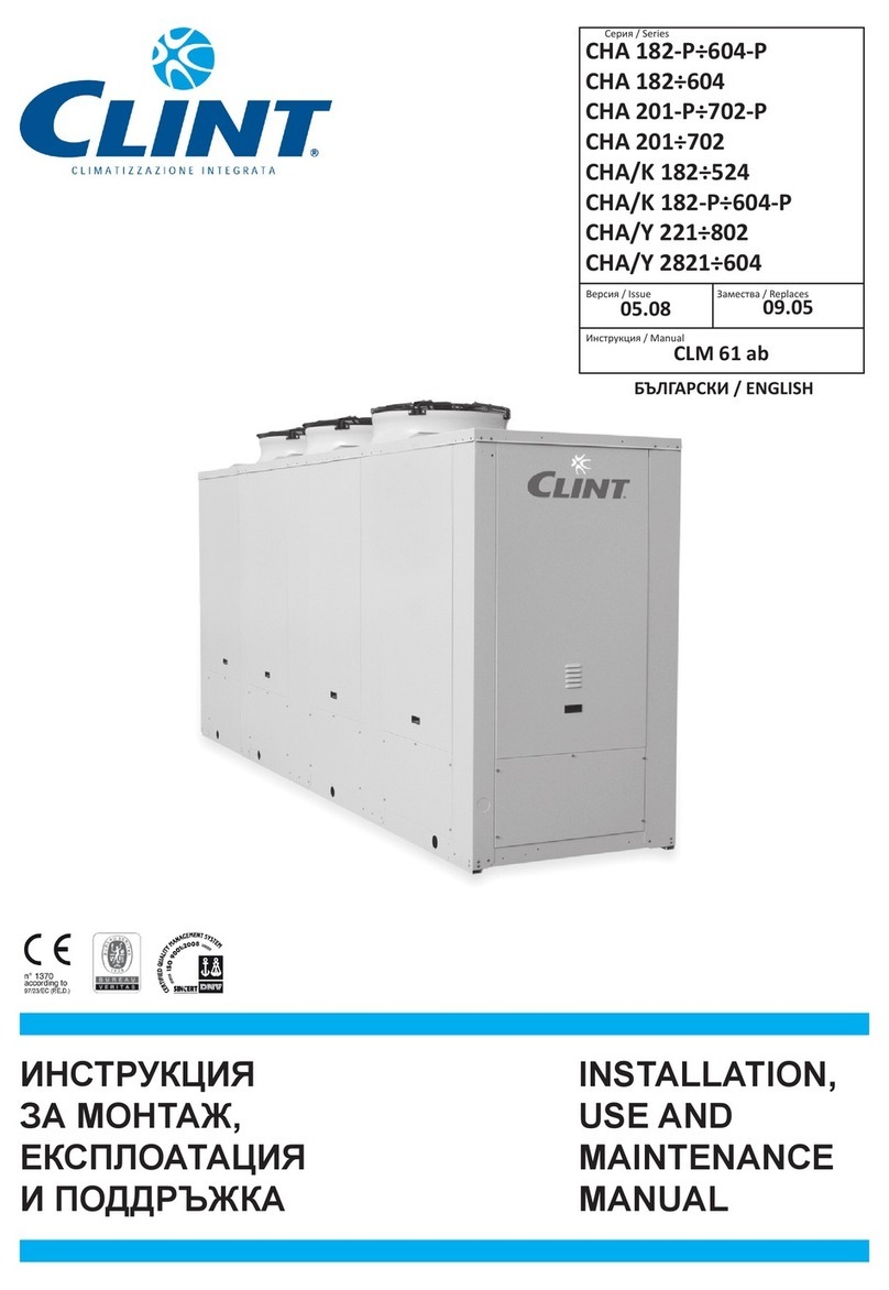
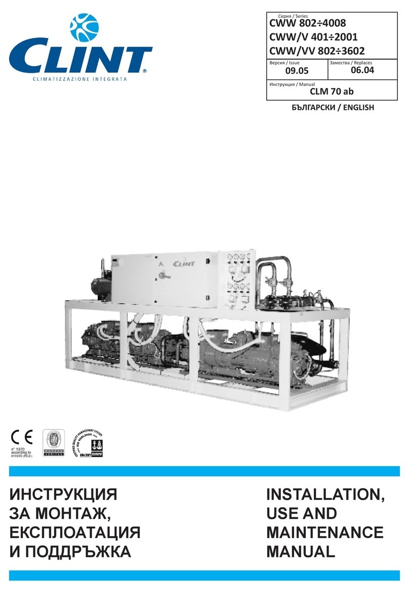
  9. Clint CWW 702-V Series User manual

Clint CWW 702-V Series User manual

This manual suits for next models

21

Other Clint Chiller manuals

Clint CHA Series Quick start guide

Clint

Clint CHA Series Quick start guide

Clint CWW Series User manual

Clint

Clint CWW Series User manual

Clint MEA 1302-B User manual

Clint

Clint MEA 1302-B User manual

Clint CHA/K Series Service manual

Clint

Clint CHA/K Series Service manual

Clint CWW 18/C Series User manual

Clint

Clint CWW 18/C Series User manual

Clint idroinverter CHA/IK Series Quick start guide

Clint

Clint idroinverter CHA/IK Series Quick start guide

Clint R410A User manual

Clint

Clint R410A User manual

Clint FVW Series Service manual

Clint

Clint FVW Series Service manual

Clint CHA 182-P-604-P User manual

Clint

Clint CHA 182-P-604-P User manual

Clint CWW/Y/A 1302 User manual

Clint

Clint CWW/Y/A 1302 User manual

Clint MultiPower CHA 726-P User manual

Clint

Clint MultiPower CHA 726-P User manual

Clint CHA 182-P-604-P Quick start guide

Clint

Clint CHA 182-P-604-P Quick start guide

Clint CHA/K/FC Series User manual

Clint

Clint CHA/K/FC Series User manual

Popular Chiller manuals by other brands

Trane RTAA-70 Installation & maintenance guide

Trane

Trane RTAA-70 Installation & maintenance guide

Carrier Omnizone 50BVC Installation, Start-Up, Service and Controls Operation and Troubleshooting

Carrier

Carrier Omnizone 50BVC Installation, Start-Up, Service and Controls Operation and Troubleshooting

York YGWH 115 Installation, commissioning & operation

York

York YGWH 115 Installation, commissioning & operation

Galletti PERFORMA MPE Series Technical manual

Galletti

Galletti PERFORMA MPE Series Technical manual

SMC Networks HRR Series manual

SMC Networks

SMC Networks HRR Series manual

Daikin EWAQ016CAW Installation and operation manual

Daikin

Daikin EWAQ016CAW Installation and operation manual

Trane CVHE Troubleshooting

Trane

Trane CVHE Troubleshooting

Moffat Friginox TSR-11SC Specification sheet

Moffat

Moffat Friginox TSR-11SC Specification sheet

Gree GWH07AGA-K6DNA1C Service manual

Gree

Gree GWH07AGA-K6DNA1C Service manual

MP Systems PURGE Series manual

MP Systems

MP Systems PURGE Series manual

Penguin COLD THERAPY CHILLER owner's manual

Penguin

Penguin COLD THERAPY CHILLER owner's manual

Telemark TVP-2000 Operation, installation and service manual

Telemark

Telemark TVP-2000 Operation, installation and service manual

TICA MINI VRF CHR Series Installation & operation manual

TICA

TICA MINI VRF CHR Series Installation & operation manual

MAXA A68 Installation and operation manual

MAXA

MAXA A68 Installation and operation manual

AERMEC NRL FC 2000 installation manual

AERMEC

AERMEC NRL FC 2000 installation manual

SABROE ChillPAC operating manual

SABROE

SABROE ChillPAC operating manual

Aqua Optima Corona Instructions for use

Aqua Optima

Aqua Optima Corona Instructions for use

Nordcap SKF 5 GN 1 manual

Nordcap

Nordcap SKF 5 GN 1 manual

manuals.online logo
manuals.online logoBrands
  • About & Mission
  • Contact us
  • Privacy Policy
  • Terms and Conditions

Copyright 2025 Manuals.Online. All Rights Reserved.

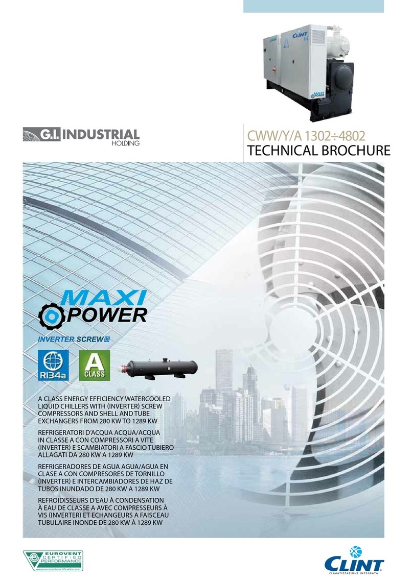
R407C
SCREW
REFRIGERATORI D’ACQUA E
POMPE DI CALORE ACQUA/ACQUA
CON COMPRESSORI A VITE
DA 185 kW A 1630 kW
WATERCOOLED LIQUID CHILLERS
AND HEAT PUMPS WITH
SCREW COMPRESSORS
FROM 185 kW TO 1630 kW
Serie / Series / Serie / Série
Emissione / Issue
Ausgabe / Edition
Sostituisce / Supersedes
Ersetzt / Remplace
Catalogo / Catalogue / Katalog / Brochure
CWW 702-V ÷ 5602-V
09.08
CLB 58.5
07.06
GROUPES DE PRODUCTION D’EAU
GLACÉE À CONDENSATION À EAU
ET POMPES À CHALEUR AVEC
COMPRESSEURS À VIS
DE 185 kW À 1630 kW
FLÜSSIGKEITSKÜHLER UND
WÄRMEPUMPE WASSERGEKÜHLT MIT
SCHRAUBEN VERDICHTERN
VON 185 kW BIS 1630 kW
2
3
INDICE Pag.
•Descrizione generale 4
•Versioni 4
•Caratteristiche costruttive 4
•Accessori montati in fabbrica 4-6
•Accessori forniti separatamente 4-6
•Condizioni di riferimento 6
•Limiti di funzionamento 6
•Dati tecnici 8-9
•Rese in raffreddamento 12-13
•Perdite di carico circuito idraulico - Evaporatore 14
•Limiti portata acqua evaporatore 14
•Fattori di correzione - Evaporatore 14
•Coefficienti correttivi per fattori
di sporcamento evaporatore 14
•Perdite di carico circuito idraulico - Condensatore 15
•Limiti portata acqua condensatore 15
•Fattori di correzione - Condensatore 15
•Coefficienti correttivi per fattori
di sporcamento condensatore 15
•Schema circuito frigorifero:
Unità per solo raffreddamento 16
•Circuito idraulico:
Caratteristiche generali 17
Schema circuito idraulico 17
•Dimensioni d'ingombro, spazi di rispetto e
distribuzione pesi 18-19
•Pressione sonora 20
•
Sistema di regolazione con microprocessore
21
•Legenda schemi circuiti elettrici 22
•Schemi circuiti elettrici 23-25
•Consigli pratici di installazione 26
INDEX Pag.
•General description 4
•Versions 4
•Technical features 4
•Factory fitted accessories 4-6
•Loose accessories 4-6
•Reference conditions 6
•Operating range 6
•Technical data 8-9
•Cooling capacity 12-13
•Water circuit pressure drops - Evaporatore 14
•Evaporator water flow limits 14
•Correction factors - Evaporator 14
•Evaporator fouling factors
corrections 14
•Water circuit pressure drops - Condenser 15
•Condenser water flow limits 15
•Correction factors - Condenser 15
•Condenser fouling factors
corrections 15
•Refrigeration circuit diagram:
Only cooling units 16
•Water circuit:
General characteristics 17
Water circuit diagram 17
•Dimensions, weights and clearancesand clearances 18-19
•Sound pressure level 20
•Microprocessor control system 21
•Wiring diagrams explanation 22
•Wiring diagrams 23-25
•Installation recommendations 26
INHALTSVERZEICHNIS Seite
•Allgemeines 5
•Bauvarianten 5
•Konstruktionsmerkmale 5
•Im Werk montiertes Zubehör 5-7
•Lose mitgelieferten Zubehöre 5-7
•
Richtwerte Bedingungen am Gerätestandort
7
•Einsatzbereich 7
•Technische daten 10-11
•Kälteleistungen 12-13
•Wärmetauscher-Druckverlust e des
hydraulischen Kreislaufs - Verdampfer 14
•Verdampfer Wassermengerenzen 14
•Korrektionfaktoren - Verdampfer 14
•Korrekturkoeffizienten für
Verschmutzungsfaktoren - Verdampfer 14
•Wärmetauscher-Druckverlust e des
hydraulischen Kreislaufs - Verflüssiger 15
•Verflüssiger Wassermengerenzen 15
•Korrektionfaktoren - Verflüssiger 15
•Korrekturkoeffizienten für
Verschmutzungsfaktoren - Verflüssiger 15
•Kältekreislaufschema:
Einheit nür Kühlung 16
•Wasserkreislauf:
Allgemeine Merkmale 17
Hydraulisches Schema 17
•Außenmaße, Raumbedarf und Gewichtsverteilung 18-19
•Schalldruckpegelhalldruckpegel 20
•
Funktion und ausstattung der Mikroprozessorregelungen
21
•Schaltpläne Erklärung 22
•Schaltpläne 23-25
•Hinweise zur Installation 27
INDEX Pag.
•Généralités 5
•Versions 5
•Caractéristiques techniques 5
•Accessoires montés en usine 5-7
•Accessoires fournis separement 5-7
•Conditions de référence 7
•Limites de fonctionnement 7
•Données techniques 10-11
•Puissance frigorifique 12-13
•Pertes de charge circuit hydraulique - Évaporateur 14
•Limites débit d'eau évaporateur 14
•Facteurs de correction - Évaporateur 14
•Coefficients correcteurs pour facteurs
d’encrassements évaporateur 14
•Pertes de charge circuit hydraulique - Condenseur 15
•Limites débit d'eau condenseur 15
•Facteurs de correction - Condenseur 15
•Coefficients correcteurs pour facteurs
d’encrassements condenseur 15
•Schema du circuit frigorifique:
Groupe de production d’eau glacée 16
•Circuit hydraulique::
Caractéristiques générales 17
Circuit hydraulique 17
•Encombrements, espaces pour entretien etespaces pour entretien et
distribution des poids 18-19
•Niveaux de pression sonore 20
•Systeme de réglage avec microprocesseur 21
•Explication de le diagrammes 22
•Diagrammes électriques 23-25
•Conseils pratiques pour l'installation 27
4
DESCRIZIONE GENERALE
Refrigeratori d’acqua condensati ad acqua per installazione
interna. La gamma comprende 20 modelli che coprono poten-
zialità frigorifere da 185 a 1630 kW.
VERSIONI:
CWW - solo raffreddamento
CWW/SSL - solo raffreddamento super silenziata
CARATTERISTICHE COSTRUTTIVE:
Struttura. Di tipo autoportante, realizzata in lamiera zincata con
un’ulteriore protezione ottenuta tramite verniciatura a polveri
poliestere. Questo tipo di struttura sorregge i componenti prin-
cipali e permette un facile accesso ad essi per le operazioni di
manutenzione e riparazione.
Compressori. Semiermetici a vite, con separatore olio incorpo-
rato, riscaldatore del carter, spia livello olio, protezione termica
e rubinetti d’intercettazione.
Condensatore. Del tipo a mantello e fascio tubiero con testate
in ghisa facilmente asportabili per una semplice manutenzione.
E’ previsto un condensatore per ogni circuito frigorifero. Col-
legamenti idraulici per funzionamento con acqua di torre.
Evaporatore.Deltipoamantelloe fascio tubiero con due circuiti
indipendenti sul lato refrigerante ed uno sul lato acqua.
Quadro elettrico. Include: interruttore generale con blocco-
porta, fusibili, relè termici a protezione dei compressori, relè di
interfaccia e morsetti per collegamenti esterni.
Microprocessoreperlagestioneautomaticadell’unità.Permette
di visualizzare in qualsiasi istante lo stato di funzionamento
dell’unità, di controllare la temperatura dell’acqua impostata e
quella effettiva e, in caso di blocco parziale o totale dell’unità,
di evidenziare quali sicurezze sono intervenute.
Circuito frigorifero. Ciascuna unità include due circuiti frigoriferi
indipendenti. Realizzato in tubo di rame, comprende per tutti i mod-
elli i seguenti componenti: valvola di espansione termostatica con
equalizzazione esterna, elettrovalvola sulla linea del liquido (pump
down),filtrodisidratatore,indicatorediliquidoedumidità,pressostati
di alta e bassa pressione (a taratura fissa) e valvola di sicurezza.
Circuito idraulico. Include: evaporatore, sonda di lavoro, sonda
antigelo, sfiato aria e scarico acqua.
ACCESSORI MONTATI IN FABBRICA:
IM - Interrutori magnetotermici in alternativa a fusibili e relè
termici.
RZ - Parzializzazione continua dei compressori per
l'adeguamento della potenza frigorifera al carico termico
dell'impianto.
HR - Desurriscaldatore con recupero del 20%.
HRT- Recuperatore calore totale con recupero del 100%.
RF - Rubinetto circuito frigorifero sulla linea del liquido.
FE - Resistenza antigelo evaporatore ad inserimento ter-
mostatato.
SS - Soft start per la limitazione della corrente di spunto
all'avviamento del compressore.
DP - Dispositivoperilfunzionamentoapompadicalore.Include
sondeditemperaturaperingressoeduscitaacquaalcondensatore
che provvedono all'avviamento e all'arresto dei compressori.
CP - Contatti puliti per segnalazione a distanza.
ACCESSORI FORNITI SEPARATAMENTE:
MN - Manometri alta/bassa pressione per ogni circuito
frigorifero.
CR - Pannello comandi remoto da inserire in ambiente per
il comando a distanza dell’unità, con funzioni identiche a quello
inserito in macchina.
GENERAL DESCRIPTION
Water cooled liquid chiller units for indoor installation. The
range consists of 20 models covering a cooling capacity from
185 to 1630 kW.
VERSIONS:
CWW - cooling only
CWW/SSL - super silenced cooling only
TECHNICAL FEATURES:
Frame. The unit features a galvanized steel frame further pro-
tected with polyester powder painting. The frame supports the
main components and allows easy acess for maintenance and
other necessary operations.
Compressors. Screw semihermetic, with built-in oil separator,
cranckcase heater, oil sight glass, thermal protection andinter-
cepting valves.
Condenser. Shell and tube type, with easily removable cast
iron heads to enable acess for maintenance operations. Each
refrigerant circuit is supplied with an indipendent condenser.
Water connections for cooling tower operation.
Evaporator. Shell and tube type, with two indipendent refriger-
ants circuits and one water circuit.
Electricalboard. Includes:mainswitchwithdoorsafetyinterlock;
fuses, overload protection for compressors; interface relays and
electrical terminals for external connections.
Microprocessor for automatic control of the unit allowing con-
tinuous display of the operational status of the unit, control set
and real water temperature and, in case of partial or total block
of the unit, indication of security device that intervened.
Refrigerant circuit. Each unit includes two independent re-
frigerant circuits. Produced in copper tubing, all models have
the following components: thermostatic expansion valve with
external equalisation, electro valve on liquid line (pump down),
lter-drier, level and humidity indicator, high and low pressure
switches (with xed setting) and safety valve.
Water circuit. Includes: evaporator, temperature sensor, anti-
freeze sensor, air vent and water drain.
FACTORY FITTED ACCESSORIES:
IM - Magnetothermic switches instead of fuses and thermal
relays.
RZ - Stepless regulation of the compressor to adjust the
cooling capacity to the termic load of the system.
HR - Desuperheater with 20% heat recovery.
HRT - Total heat recovery for 100% heat recovery.
RF - Cooling circuit shut off valve on liquid line.
FE - Evaporator heater with thermostatic control.
SS - Soft start to reduce compressor starting current.
DP - Device for the heat pump functioning. Includes: water
inletand outlet temperaturesensors on the condenser to control
the compressor start and stop.
CP - Potential free contacts for remote alarm and control.
LOOSE ACCESSORIES:
MN - High and low pressure gauges for every refrigeration
circuit.
CR - Remote control panel to be inserted in the room for
remote control of the unit, with the same functions as that
inserted in the machine.
5
ALLGEMEINE EIGENSCHAFTEN
Wassergekühlte Flüssikeitskühler für Innenaufstellung. Die
Produktpalette besteht aus 20 Modellen, die Kälteleistungsbe-
reich von 185 bis 1630 kW abdecken.
BAUVARIANTEN:
CWW - nur Kühlung
CWW/SSL - nur Kühlung, super schallisoliert
KONSTRUKTIONSMERKMALE:
Struktur. Selbsttragend, bestehend aus verzinktem Rahmen,
pulverbeschichtet mit polyesterlacken. Diese Struktur trägt die
Hauptbestandteilen und ist leicht zugänglich für die Wartung
bzw. Reparatur.
Verdichter. Halbhermetisch schrauben mit intergriertem Ölab-
scheiderundCarterÖlwannenheizung,Ölschauglas,thermischen
Schutz und Rückschlagventilen.
Verflüssiger. Der Rohrbündel-Verflüssiger mit abnehmbarem
Kopf aus Gußeisen ist leicht zugänglich für die Wartung. Es ist je
KältekreislaufeinVerflüssigervorgesehen.DieWasseranschlüsse
sind für Turmwasser geeignet.
Verdampfer. Rohrbündel mit Kupferrohren, Mantel aus Koh-
lensoffstahl. Zwei unabhängige Kältekreisläufe.
Schaltschrank. Ausgestattet mit: Hauptschalter als Lasttrenn-
schalterindenTüren,Sicherungen,BirelaisanVerdichtern,Schnitt-
stellenrelais und Klemmenleiste für externe Ansteuerung.
Mikroprozessor zur automatischen Anlagensteuerung; dieser
ermöglicht jederzeit die Funktionskontrolle der Anlage und
zeigt Soll-und Istwert der Wassertemperaturen an. Ausserdem
werden Störungen und aktivierte Sicherheitseinrichtungen
angezeigt.
Kühlkreislauf. Jedes Gerät verfügt über zwei unabhängige Kühl-
kreisläufe aus Kupferrohren, bei allen Modellen mit folgenden
Komponenten: thermostatisches Expansionsventil mit externem
Ausgleich,ElektroventilaufderFlüssigkeitslinie(Pumpdown),Ent-
feuchtungsfilter,Flüssigkeit-undFeuchtigkeitsanzeiger,Hoch-und
Niederdruckschalter (feste Einstellung) und Sicherheitsventil.
Wasserkreislauf. Bestehend aus: Verdampfer, Temperatur- und
Frostschutzfühler, Entlüftung und Wasser Entladen.
IM WERK MONTIERTES ZUBEHÖRE:
IM - Motorschutzschalter. ersetzen Sicherungen und ther-
mische Relais.
RZ - Stufenlose Regelung der Verdichter , um die Kälteleis-
tung mit der thermischen Last der Anlage einzustellen.
HR- Überhitzungsschutz mit 20% Wärmerückgewinnung.
HRT - Total Wärmerückgewinner von 100% Wärmerückgewin-
nung.
RF - Absperrventil auf dem Kältekreislauf auf der Flüssig-
keitslinie.
FE - Begleitheizung am Verdampfer Thermostat geregelt.
SS - Sanftanlasser zur Reduzierung des Verdichter Anlauf-
stroms.
DP - Vorrichtung für die Wärmepumpe Funktion. Enthält:
Wasser Ein- und Austrittstemperatur Fühler an dem Konden-
sator zur Ein- und Ausschaltung der Verdichter.
CP - Potentialfreie Kontakte für externe Ein/Ausschaltung.
LOSE MITGELIEFERTEN ZUBEHÖRE:
MN - Hoch/Niedrigdruckmanometer für jeden Kühl-
kreislauf.
CR - Fernbedienung die am Standort installiert wird und
von der aus eine Fernsteuerung der Einheit möglich ist. Mit
den gleichen Funktionen wie das Gerät.
DESCRIPTION GÉNÉRALE
Groupe d’eau glacée à condensation à eau pour installation
à l’intérieur. La gamme est composée de 20 modèles d’une
puissance de 185 iusqu’à 1630 kW.
DIFFÉRENTES VERSIONS:
CWW - uniquement refroidissement
CWW/SSL - uniquement refroidissement ultra silencieux
CARACTERISTIQUES:
Structure. Structure autoportante en tôle galvanisée et proté-
gée par une couche de peinture à poudre polyestère. La struc-
ture porte tous les composants principaux et permet un accès
facile pour toutes les opérations de maintenance et réparation.
Compresseur. À vis semihermetique, avec separateur de
l’huile incorporé, réchauffage de l’huile, voyant pour niveau del
l’huile, protection thermique et robinets d’interceptation.
Condenseur. Echangeur à faisceaux de tuyaux avec la pos-
sibilité d’enlever les tetes en fonte pour avoir accès en cas de
maintenance. Chaque circuit frigorifique a son échangeur indé-
pendent. Les raccords sont pour eau de tour.
Evaporateur. Échangeur à faisceaux de tuyaux avec deux cir-
cuits indipéndants.
Tableau electrique. Comprend: sectionneur générale sur porte,
fusibles, relais de protection thermique pour compresseur, relais
d'interface et bornier pour raccordements extérieurs.
Microprocesseur pour gérer automatiquement l'unité ce qui
permet de visualiser sur voyant les paramètres de fonction-
nement de la machine, de contrôler le point de consigne et
température réelle de l'eau, et, en cas d'arrêt partiel ou total
de l'unité, d'indiquer l'alarme correspondante.
Circuit frigorifique. Chaque unité comprend deux circuits frigoriques
indépendants. Réalisé en tuyau de cuivre, pour tous les modèles sont
inclus les composants suivants: soupape d’expansion thermostatique
avec équalisation externe, électrovanne sur la ligne liquide (pump
down), ltre déshydrateur, voyant de liquide et d’humidité, pressotats
de haute et basse pression (à calibrage xe) et soupape de securité.
Circuithydraulique.Lecircuitinclut:évaporateur,sondedetravail,
sonde anti-gel, purge d’air et vidange d'eau.
ACCESSOIRES MONTÈS EN USINE:
IM - Interrupteurs magnétothermiques ouen alternativedes
fusibles et relais thermique.
RZ - Partialisation ètages des compresseurs. pour adapter
la puissance frigorique au charge termique de l'équipe-
ment.
HR - Désurchauffeur avec récupération de 20%.
HRT - Récupérateur chaleur totale avec récupération du 100%.
RF - Robinet circuit frigo sur liquide.
FE - Resistances antigel evaporateur contrôle thermostatique.
SS - Soft start pour reduction courant au demarrage du com-
presseur.
DP -Dispositifpourlefonctionnementpompeachaleur.Ilinclut
sondesdetempératurepourentréeetsortiedel’eauaucondensateur
qui pourvoient au démarrage et l’arrête des compresseurs.
CP - Contcts secs pour signalisation à distance.
ACCESSOIRES FOURNIS SEPAREMENT:
MN - Manomètreshaute/bassepressionpourchaquecircuit
frigorique.
CR - Tableau de commandes à distance à insérer dans un
environnement pour la commande à distance de l’unité, avec
fonctions identiques à celles insérées dans la machine.
6
CONDIZIONI DI RIFERIMENTO
I dati tecnici, indicati a pagina 8 e 9, si riferiscono alle seguenti
condizioni di funzionamento:
- in raffreddamento:
• temperatura ingresso acqua fredda 12°C.
• temperatura uscita acqua fredda 7°C.
• temperatura ingresso acqua al condensatore 30 °C.
• temperatura uscita acqua al condensatore 35 °C.
- in riscaldamento:
• temperatura ingresso acqua 40°C
• temperatura uscita acqua 45°C
• temperatura ingresso acqua all'evaporatore 10 °C.
- pressione sonora (DIN 45635):
rilevata in campo libero a 1 m di distanza e ad 1,5 m dal suolo.
Secondo normativa DIN 45635.
- pressione sonora (ISO 3744):
rilevata in campo libero a 1 m dall'unità. Valore medio definito
dalla ISO 3744.
L'alimentazione elettrica di potenza é 400V/3Ph/50Hz; l'alimenta-
zione elettrica ausiliaria é 230V/1Ph/50Hz.
REFERENCE CONDITIONS
All technical data, indicated on pages 8 e 9, refer to the following
unit operating conditions:
- cooling:
• entering water temperature 12°C.
• leaving water temperature 7°C.
• condenser entering water temperature 30°C.
• condenser leaving water temperature 35°C.
- heating:
• entering water temperature 40°C.
• leaving water temperature 45°C.
• evaporator entering water temperature 10°C.
- sound pressure level (DIN 45635):
measured in free eld conditions at 1 m from the unit and at 1,5 m
from the ground. According to DIN 45635.
- sound pressure level (ISO 3744):
measured in free eld conditions at 1 m. As dened by ISO 3744.
The power supply is 400V/3Ph/50Hz; auxiliary supply is 230V/1Ph/
50Hz.
IS - Interfaccia seriale RS 485 per collegamento a sistemi
di controllo e di supervisione centralizzati.
PV3 - Valvola pressostatica a 3 vie per il controllo della
condensazione.
AG - Antivibranti in gomma da inserire alla base dell’unità
per smorzare eventuali vibrazioni dovute al tipo di pavimento
ove la macchina è installata.
AM - Antivibranti a molla da inserire alla base dell’unità per
smorzare eventuali vibrazioni dovute al tipo di pavimento ove
la macchina è installata.
FL - Flussostato a protezione dell'evaporatore da possibili
interruzioni del flusso d'acqua.
IS - RS 485 serial interface for connection to controls and
centralized supervision systems.
PV3 - 3-ways pressostatic valve to control the condensa-
tion.
AG - Rubber vibration dampers to be inserted at the bottom
of the unit to dampen possible vibrations due to the type of oor
where the machine is installed.
AM - Spring shock absorbers to be inserted at the bottom of
the unit to dampen possible vibrations due to the type of oor
where the machine is installed.
FL - Flow switch to prevent any water ow interruption.
LIMITI DI FUNZIONAMENTO min max OPERATING RANGE
Temperatura acqua in ingresso evaporatore °C 8 20 Evaporator inlet water temperature
Temperatura acqua in uscita evaporatore °C 5 15 Evaporator outlet water temperature
Salto termico acqua evaporatore (1) °C 3 9 Evaporator water thermal difference (1)
Temperatura acqua in ingresso condensatore °C 10 45* Condenser inlet water temperature
Temperatura acqua in uscita condensatore °C 25 50** Condenser outlet water temperature
Salto termico acqua condensatore (1) °C 4 12 Condenser water thermal difference (1)
Minima temperatura dell'acqua refrigerata con
l'impiego di glicole °C - 8 Min. chilled water/glycol temperature
Max. pressione di esercizio lato acqua
evaporatore kPa 1000 Max. operating pressure evaporator water side
Max. pressione di esercizio lato acqua
condensatore kPa 1000 Max. operating pressure condenser water side
(1) Inogni casola portatad'acquadovràrientrareneilimiti riportati
a pagg. 14-15.
* 42 °C per i modelli 5002-V; 5602-V;
** 47 °C per i modelli 5002-V; 5602-V.
(1) In all cases the water range will have to re-enter within the
reported limits on pagg. 14-15.
* 42 °C for models 5002-V; 5602-V;
** 47 °C for models 5002-V; 5602-V.
7
CONDITIONS DE RÉFÉRENCE
Les données techniques, indiquées page 10 et 11; se réfèrent
aux conditions de fonctionnement suivantes:
- refroidissement:
• température d’entrée de l’eau froide: 12°C
• température de sortie de l’eau froide: 7°C
• température d’entrée de l’eau au condenseur 30°C.
• température de sortie de l'eau au condenseur 35°C.
- rechauffage:
• température d’entrée de l’eau 40°C
• température de sortie de l’eau 45°C
• température d’entrée de l’eau au evaporateur 10°C.
- pression sonore (DIN 45635):
mèsuré en champs libre à 1 métre de l'unité et à 1,5 métres du
sol. Selon normes DIN 45635.
- pression sonore (ISO 3744):
niveau moyen de pression sonore en champ libre à 1m de l'unité.
Comme déni de ISO 3744.
L’alimentation électrique de puissance est de 400V/3Ph/50Hz,
l’alimentation électrique auxiliaire est de 230V/1Ph/50 Hz.
BEZUGS - UND AUSLEGUNGSDATEN
Diehierangegebenentechnischen Daten, Seite 10 und 11,beziehen
sich auf folgenden Auslegungsdaten:
- im Kühlbereich:
• Kaltwassereintrittstemperatur 12°C;
• Kaltwasseraustrittstemperatur 7°C;
• Wassertemperatur am Verflüssigereintritt 30 °C.
• Wassertemperatur am Verflüssigeraustritt 35 °C.
- im Heizbereich:
• Wassereintrittstemperatur 40°C;
• Wasseraustrittstemperatur 45°C;
• Wassertemperatur am Verdampfereintritt 10 °C.
- schalldruckpegel (DIN 45635):
messungineinemMeter Abstand gegenüber der Verflussigerseite,
in einer Höhe von 1,5 m. Gemab DIN 45635.
- schalldruckpegel (ISO 3744):
Mittlerer Schalldruck in 1 m von der Einheit in freien Feld, wie von
ISO 3744 angegeben.
Separate Einspeisung von 400V/3Ph/50Hz; Steuerspannung
230V/1Ph/50Hz wird mittels montierte Trenntrafos erzeugt.
IS - Serielle Schnittstelle RS 485 für den Anschluss an Kon-
trolllsysteme oder zentrale Supervisor.
PV3 - 3-Wege pressostatisches Ventil zur Regelung der
Kondensation.
AG - Gummi Schwingungsdämpfer werden unter der Einheit
zur Dämpfung eventueller Vibrationen eingesetzt, die von dem
Bodentypverursachtwerdenkönnen,aufdemdieEinheitinstalliert
ist.
AM - Feder Schwingungsdämpfer werden unter der Einheit zur
DämpfungeventuellerVibrationeneingesetzt,dievondemBodentyp
verursacht werden können, auf dem die Einheit installiert ist.
FL - Strömungswächter zur Wassermängel Vermeidung am
Verdampfer.
IS - Interface de série RS 485 pour branchement à système
de contrôle et de supervision centralisées.
PV3 - Valve pressostatic à 3 voies pour commander la
condensation.
AG - Antivibreurs en caoutchouc à insérer à la base de
l’unité pour estomper les vibrations éventuelles dues au type
de sol sur lequel la machine est installée.
AM - Antivibreurs à ressort à insérer à la base de l’unité
pour estomper les vibrations éventuelles dues au type de sol
sur lequel la machine est installée.
FL - Controlleur de débit à protection de l'evaporateur en cas
d'interruptions du debit d'eau.
(1) Die Wasser Durchflußmenge muss jedenfalls den auf der
Tabelle Seiten 14-15 Grenzen entsprechen.
* 42 °C für die Modelle 5002-V; 5602-V;
** 47 °C für die Modelle 5002-V; 5602-V.
(1) Dans chacun des cas la portée d'eau devra rentrer dans limites
reportées à pagg. 14-15.
* 42 °C pour modéles 5002-V; 5602-V;
** 47 °C pour modéles 5002-V; 5602-V.
BETRIEBSGRENZEN min max LIMITES DE FONCTIONNEMENT
Verflüssiger Wassereintrittstemperatur °C 8 20 Température eau entrée condenseur
Verflüssiger Wasseraustrittstemperatur °C 5 15 Température eau entrée condenseur
Verflüssiger Wassertemperaturdifferenz (1) °C 3 9 Ecart de température condenseur (1)
Verdampfer Wassereintrittstemperatur °C 10 45* Température eau entrée evaporateur
Verdampfer Wasseraustrittstemperatur °C 25 50** Température eau entrée evaporateur
Verdampfer Wassertemperaturdifferenz (1) °C 4 12 Ecart de température evaporateur (1)
Min. Kaltwasser/Glykol Temperatur °C - 8 Température minimum de l'eau réfrigéré avec
l'emploi de glicole
Max. Betriebsdruck Verflüssiger Wasser-Seite kPa 1000 Pression maximun d’utilisation échangeur côte
eau
Max. Betriebsdruck Verdampfer Wasser-Seite kPa 1000 Pression maximun d’utilisation evaporateur côte
eau
8
(1) Condizioni di riferimento a pagina 6.
R407C
DATI TECNICI GENERALI
MODELLO 702-V 802-V 902-V 1102-V 1202-V 1502-V 1602-V 1802-V 2002-V 2202-V
Raffreddamento:
Potenza frigorifera (1) kW 185 226 246 291 319 370 427 470 526 605
Potenza assorbita (1) kW 47 58 62 72 78 90 103 116 125 140
Riscaldamento:
Potenza termica (1) kW 212 255 282 323 355 412 475 534 581 671
Potenza assorbita (1) kW 54 65 71 80 86 99 114 132 137 153
Compressori n° 2 2 2 2 2 2 2 2 2 2
Circuiti frigoriferi n° 2 2 2 2 2 2 2 2 2 2
Gradini di parzializzazione % < - - - - - - - - - - - - - - - - - - 0 / 25 / 37 / 50 / 75 / 87 / 100 - - - - - - - - - - - - - - - - - - - >
Evaporatore:
Portata acqua (1) l/s 8,84 10,80 11,75 13,90 15,24 17,68 20,40 22,46 25,13 28,91
Perdite di carico (1) kPa 52 62 43 53 30 39 44 53 53 57
Attacchi idraulici DN 100 100 125 125 125 125 150 150 150 200
Contenuto acqua dm³ 50 55 105 105 100 90 145 135 120 230
Condensatore:
Portata acqua (1) l/s 11,08 13,57 14,72 17,34 18,97 21,98 25,32 28,00 31,10 35,59
Perdite di carico (1) kPa 46 48 43 43 55 58 55 39 50 44
Attacchi idraulici ”G 2” 2” 2½” 2½” 2½” 2½” 2½” DN80 DN80 DN80
Contenuto acqua dm³ 20 22 27 30 34 37 46 56 62 66
Compressore:
Potenza assorbita unitaria (1) kW 23,6 29,1 31,2 36,2 38,9 45,1 51,6 57,9 62,3 70,2
Corrente assorbita unitaria (1) A 42,6 52,0 55,5 64,5 68,5 79,1 90,4 101 108 120
Carica olio unitaria Kg 7 6 7 6 6 8 7 14 10 16
Versione standard:
Pressione sonora - DIN (1) dB(A) 74 74 74 74 75 75 75 77 77 77
Pressione sonora - ISO (1) dB(A) 63 63 63 63 64 64 64 66 66 66
Carica refrigerante R407C Kg 30 30 42 42 44 44 56 76 82 74
Lunghezza unità mm 3300 3300 3300 3300 3300 3300 3300 3100 3100 3100
Larghezza mm 780 780 780 780 780 780 780 1420 1420 1420
Altezza mm 2000 2000 2000 2000 2000 2000 2000 2150 2150 2150
Peso di trasporto unità
Kg 1150 1310 1285 1410 1575 1845 2010 2060 2295 2460
Versione SSL:
Pressione sonora - DIN (1) dB(A) 68 68 68 68 69 69 69 71 71 71
Pressione sonora - ISO (1) dB(A) 57 57 57 57 58 58 58 60 60 60
Carica refrigerante R407C Kg 30 30 42 42 44 44 56 76 82 74
Lunghezza unità mm 3300 3300 3300 3300 3300 3300 3300 3100 3100 3100
Larghezza mm 780 780 780 780 780 780 780 1420 1420 1420
Altezza mm 2000 2000 2000 2000 2000 2000 2000 2150 2150 2150
Peso di trasporto unità
Kg 1550 1710 1685 1810 1975 2245 2410 2460 2695 2860
Assorbimenti
Alimentazione
V/Ph/
Hz <- - - - - - - - - - - - - - - - - - - - - - - -- 400 / 3 / 50 - - - - - - - - - - - - - - - - - - - - - - - - - ->
Corrente di spunto A 308 357 366 393 469 475 491 662 663 753
Corrente massima A 136 160 174 180 192 248 280 314 336 410
(1) Referential conditions at page 6.
9
(1) Referential conditions at page 6.
TECHNICAL DATA
2402-V 3202-V 3302-V 3402-V 3602-V 4002-V 4202-V 4602-V 5002-V 5602-V MODEL
Cooling:
633 754 843 897 931 1026 1096 1332 1508 1630 kW Cooling Capacity (1)
150 176 195 207 215 236 252 316 347 373 kW Absorbed power (1)
Heating:
700 832 928 994 1030 1135 1212 1500 --- --- kW Heating capacity (1)
165 194 215 225 237 261 278 342 --- --- kW Absorbed power (1)
2 2 2 2 2 2 2 2 2 2 n° Compressors
2 2 2 2 2 2 2 2 2 2 n° Refrigerant Circuits
< - - - - - - - - - - - - - - - - - - - 0 / 25 / 37 / 50 / 75 / 87 / 100 - - - - - - - - - - - - - - - - - - > % Capacity steps
Evaporator:
30,24 36,02 40,28 42,86 44,48 49,02 52,36 63,64 72,05 77,88 l/s Water ow (1)
60 49 43 45 46 60 51 53 59 56 kPa Pressure drops (1)
200 200 200 200 200 200 200 200 200 200 DN Water connections
230 215 195 240 240 210 300 440 420 480 dm³ Water volume
Condenser:
37,41 44,43 49,59 52,75 54,75 60,30 64,40 78,74 88,63 95,70 l/s Water ow (1)
51 54 58 40 41 41 42 54 30 35 kPa Pressure drops (1)
DN80 DN80 DN80 DN100 DN100 DN100 DN100 DN100 DN125 DN125 ”G Water connections
72 84 92 102 102 112 122 132 180 180 dm³ Water volume
Compressor:
75,0 88,2 97,6 103,6 107,3 118,2 126,2 158,2 173,5 186,7 kW Unitary absorbed power (1)
129 150 168 179 185 203 217 274 299 321 A Unitary absorbed current (1)
10 15 14 18 16 23 23 20 28 28 Kg Oil charge
Standard version:
77 78 79 79 80 80 80 81 82 82 dB(A) Sound pressure level - DIN (1)
66 67 68 68 69 69 68 69 70 70 dB(A) Sound pressure level - ISO (1)
80 78 78 100 100 100 100 110 136 142 Kg Refrigerant charge R407C
3100 3100 3100 3300 3300 3800 3800 3800 3800 4600 mm Unit lenght
1420 1420 1420 1450 1450 1450 1550 1550 1650 1650 mm Width
2150 2150 2150 2150 2150 2150 2200 2200 2200 2200 mm Height
2515 2845 2855 3220 3240 3830 4050 4210 4810 4980 Kg Unit transport weight
SSL version:
71 72 73 73 74 74 74 75 76 76 dB(A) Sound pressure level - DIN (1)
60 61 62 62 63 63 62 63 64 64 dB(A) Sound pressure level - ISO (1)
80 78 78 100 100 100 100 110 136 142 Kg Refrigerant charge R407C
3100 3100 3100 3300 3300 3800 3800 3800 3800 4600 mm Cooling only unit lenght
1420 1420 1420 1450 1450 1450 1550 1550 1650 1650 mm Width
2150 2150 2150 2150 2150 2150 2200 2200 2200 2200 mm Height
2915 3245 3255 3620 3640 4230 4450 4610 5210 5380 Kg Cooling only unit transport weight
Total electrical consumption:
<- - - - - - - - - - - - - - - - - - - - - - - - - 400 / 3 / 50 - - - -- - - - - - - - - - - - - - - - - - - - - ->
V/Ph/
Hz Power supply
514 579 619 693 723 843 929 995 1524 1560 A Starting current
392 450 490 552 540 600 668 800 936 1002 A Max. Current
(1) Condizioni di riferimento a pagina 6.
R407C
10
(1) Conditions de référence à page 7.
(1) Bezugs-und auslegungsdaten sehen sie Seite 7.
ALLGEMEINE TECHNISCHE DATEN
MODELLE 702-V 802-V 902-V 1102-V 1202-V 1502-V 1602-V 1802-V 2002-V 2202-V
Kühlung:
Kälteleistung (1) kW 185 226 246 291 319 370 427 470 526 605
Leistungsaufnahme (1) kW 47 58 62 72 78 90 103 116 125 140
Heizleistung:
Wärmeleistung (1) kW 212 255 282 323 355 412 475 534 581 671
Leistungsaufnahme (1) kW 54 65 71 80 86 99 114 132 137 153
Verdichter n° 2 2 2 2 2 2 2 2 2 2
Kältekreisläufe n° 2 2 2 2 2 2 2 2 2 2
Leistungsstufen % < - - - - - - - - - - - - - - - - - - 0 / 25 / 37 / 50 / 75 / 87 / 100 - - - - - - - - - - - - - - - - - - >
Verdampfer:
Kaltwassermenge (1) l/s 8,84 10,80 11,75 13,90 15,24 17,68 20,40 22,46 25,73 28,91
Druckverlust (1) kPa 52 62 43 53 30 39 44 53 53 57
Wasseranschlüsse DN 100 100 125 125 125 125 150 150 150 200
Wasserinhalt dm³ 50 55 105 105 100 90 145 135 120 230
Verflüssiger:
Kaltwassermenge (1) l/s 11,08 13,57 14,72 17,34 18,97 21,98 25,32 28,00 31,10 35,59
Druckverlust (1) kPa 46 48 43 43 55 58 55 39 50 44
Wasseranschlüsse ”G 2” 2” 2½” 2½” 2½” 2½” 2½” DN80 DN80 DN80
Wasserinhalt dm³ 20 22 27 30 34 37 46 56 62 66
Verdichter:
Abgenommene Leistung pro Einheit (1)
kW 23,6 29,1 31,2 36,2 38,9 45,1 51,6 57,9 62,3 70,2
Stromaufnahme pro Einheit (1) A 42,6 52,0 55,5 64,5 68,5 79,1 90,4 101 108 120
Ölmenge pro Einheit Kg 7 6 7 6 6 8 7 14 10 16
Standardversion:
Schalldruckpegel - DIN (1) dB(A) 74 74 74 74 75 75 75 77 77 77
Schalldruckpegel - ISO (1) dB(A) 63 63 63 63 64 64 64 66 66 66
Kältemittelfüllung R407C Kg 30 30 42 42 44 44 56 76 82 74
Einheit Länge mm 3300 3300 3300 3300 3300 3300 3300 3100 3100 3100
Breite mm 780 780 780 780 780 780 780 1420 1420 1420
Höhe mm 2000 2000 2000 2000 2000 2000 2000 2150 2150 2150
Transportgewicht Kg 1150 1310 1285 1410 1575 1845 2010 2060 2295 2460
SSL Version:
Schalldruckpegel - DIN (1) dB(A) 68 68 68 68 69 69 69 71 71 71
Schalldruckpegel - ISO (1) dB(A) 57 57 57 57 58 58 58 60 60 60
Kältemittelfüllung R407C Kg 30 30 42 42 44 44 56 76 82 74
Einheit Länge mm 3300 3300 3300 3300 3300 3300 3300 3100 3100 3100
Breite mm 780 780 780 780 780 780 780 1420 1420 1420
Höhe mm 2000 2000 2000 2000 2000 2000 2000 2150 2150 2150
Transportgewicht Kg 1550 1710 1685 1810 1975 2245 2410 2460 2695 2860
Gesamteltrodaten:
Elektrische Einspeisung
V/Ph/
Hz <- - - - - - - - - - - - - - - - - - - - - - - - - 400 / 3 / 50 - - - - - - - - - - - - - - - - - - - - - - - - ->
Anlaufstrom A 308 357 366 393 469 475 491 662 663 753
Max. Betriebsstrom A 136 160 174 180 192 248 280 314 336 410
R407C