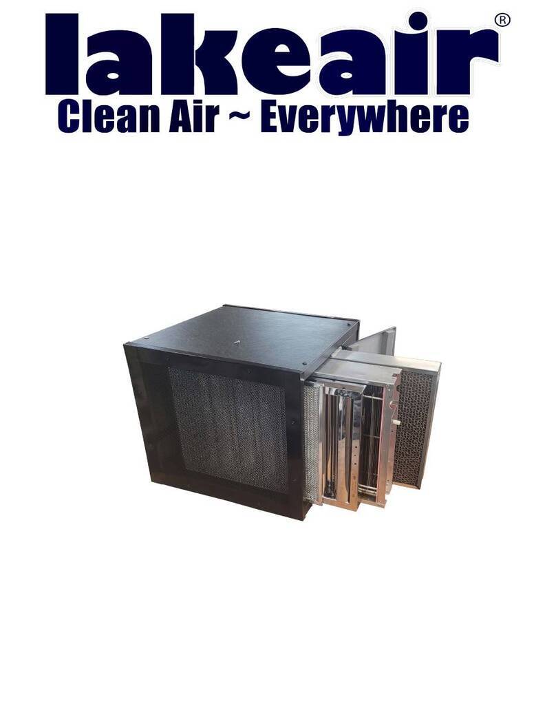
lakeair LA2000 User manual

OPERATING AND SERVICE
INSTRUCTIONS
RK Ventures Inc
www.lakeair.com
LA2000
LA2000-OC

TABLE OF CONTENTS
3
3
3
I. Introduction
A. How a LakeAir Unit Works
B. Specifications
II. Installation
A. How to Determine the Number of Electronic Air Cleaners Required Y
oAur pplication
B. Proper Location of LA2000 & LA2000-OC Electronic Air Cleaners
C. Mounting Your LakeAir Model LA2000 & LA2000-OC Electronic
AirCleaners
III. Operating Instructions
IV. Cleaning Electronic Cell(s) and Filter
A. Removal of Electronic Cell(s), Prefilter Screen, and Carbon Afterfilter
B. Cleaning the Prefilter Screen
C. Cleaning the Carbon Filter
D. Cleaning the Electronic Cell(s)
V. Repa anir Maind tenance
A. Owner’s Checklist and Return Procedure
B. Trouble Shooting Electronic Air Cleaners
C. PartsList
VI. Schematic Drawing for LA2000 & LA2000-OC
VII. Lake WarAir ranty
4-6
4
5
5-6
6
6-7
7
7
7
7-8
8-9
8
9
10
11
12

I. INTRODUCTION
A. HOW a LakeAir UNIT WORKS
In business establishments, millions of airborne particles are continually being circu-
lated through the interior environment. A LakeAir unit removes these smoke, dust
dirt, and pollen particles with an electrostatic process that works this way:
1. The circulating fan draws dirt laden air
through the PREFILTER SCREEN which
collects large lint particles.
2. Then the IONIZING SECTION, with its
many fine ion wires, charges the airborne
particles. As the charged particles move
along the collecting section, they are col-
lected on the collector plates and trapped
there (just like a magnet attracts and collects
iron fillings).
3. The optional ACTIVATED CARBON
FILTER removes odors and freshens the air.
4. The cleaned and purified air is now dis-
charged to recirculate through your establish-
ment.
B. SPECIFICATIONS
Input Voltages Model LA2000 Model LA-2000-OC
120 VAC 60 Hz
6 Amps
Model LA-1402S
120 VAC 60 Hz
6 Amps
Model LA-2002S
Capacity
Cabinet Dimensions
(H X W X D)
Approximate Shipping
Weights
230 VAC 50 Hz
3 Amps
1600-2000 CFM
45-56 m3/minute
21” X 22” X 19”
53.3 X 55.9 X48.25CM
105lbs.
47.62 kg.
230 VAC 50 Hz
3 Amps
800-1200 CFM
23-34 m3/minute
21” X 22” X 19”
53.3 X 55.9 X48.25CM
109 lbs.
49.44 kg.
3
ACTIVATED
CARBON
FILTER
ELECTRONIC
CELL
PRE-FILTER
SCREEN
IONIZING WIRE
SECTION
COLLECTING
CELL PLATES

II. INSTALLATION
CAUTION:
All external wiring must comply with applicable codes and local ordinances.
DO NOT connect power supply until air cleaner has been installed and/or checked.
A. HOW TO DETERMINE THE NUMBER OF ELECTRONIC AIR CLEANERS
REQUIRED
To determine the number of electronic air cleaners required for your business
establishments, use the method below as a guideline. If you have any questions,
call the LakeAir HOTLINE at 1-800-558-9436 and we will help you.
METHOD: SIZE BY ROOM VOLUME AND AIR CHANGES PER
HOUR
1. Calculate the volume of the room. Volume (cubic feet) = Length x Width x Height
2. Determine the circulation of the air needed, based upon 8 air changes per hour for
average conditions, to reduce the smoke and pollution. Use 16 air changes per hour for
high concentrations of smoke and contaminants, or when one has a desire to reduce smoke
and pollution even further.
3. The LA2000 and 2000-OC have differing capacities in cubic feet/minute. Both models
are two speed units with a high and a low speed of operation. The LA2000-oc produces 800
cfm at low speed and 1200 cfm at high speed. The LA2000 produces 1600 cfm at low
speed and 2000 cfm at high speed. To establish the correct unit and/or number of units to
use, you should calculate the cubic feet of air in the area to be cleaned, and then use a figure
of 8 air changes/hour in that area for average cleaning, and 16 air changes per hour for very
polluted or smoke filled conditions. You shouldremember that the slower the air passes
over the surface of the air cleaner, the more efficiently the unit will operate. Therefore,
when calculating the number of units needed, take into account air flow and cleaning
capacity.
EXAMPLE #1
ROOM DIMENSIONS:
TYPE OF AREA: 50’ X 100’ X 10’ CEILING
RESTAURANT OR LOUNGE
AIR CHANGES DESIRED: 16/HOUR
STEP 1 - VOLUME =50’ X 100’ X 10’ = 50,000 CU. FT.
STEP 2 - VOLUME TO BE CLEANED = 50,000 CU. FT. X 16 AIR CHANGES/HOUR
STEP 3 – VOLUME/MINUTE TO BE CLEANED = 800,000 CU.FT./HOUR = 13,333 CU.FT. MIN.(CFM)
60,000 MINUTES/HOUR
STEP 4 – NUMBER OF UNITS NEEDED = 13,333 CFM ÷ THE CFM OF THE CHOSEN UNIT
(MODEL LA-2000) =13,333 CFM = 6.34 OR 6 UNITS
2,100 CFM
(MODEL LA-1400) =13,333 CFM = 12.09 OR 12 UNITS
1,100 CFM
EXAMPLE #2
ROOM DIMENSIONS:
TYPE OF AREA: 50’ X 30’ X 10’ CEILING
OPEN OFFICE AREA WITH MULTIPLE PERSONNEL
AIR CHANGES DESIRED: SOME SMOKERS AND 20 DESKS – USE 8 AIR CHANGES/HOUR
STEP 1 – VOLUME = 50’ X 30’ X 10’ = 15,000 CU.FT.
STEP 2 – VOLUME TO BE CLEANED = 15,000 CU.FT. X 8 AIR CHANGES/HOUR = 120,000 CU.FT./
HOUR
STEP 3 – VOLUME/MINUTE TO BE CLEANED = 120,000 CU.FT./HOUR = 2,000 CU.FT./MINUTE(CFM)
60 MINUTES/HOUR
STEP 4 – NUMBER OF UNITS NEEDED = 2,000 CFM DIVIDED BY THE CFM OF THE CHOSEN UNIT
(MODEL LA-2000)
(MODEL LA-1400)
= 2,000 CFM = 1 UNIT
2,100 CFM
= 2,000 CFM = 1.8 OR 2 UNITS
1, CFM100
Locate Electronic Air Cleaners consistent with
existing air circulation in the room so that the
heating and air conditioning systems are comple-
mented by the air cleaners.
C. MOUNTING YOUR LakeAir MODEL LA2000 OR 2000-OC ELECTRONIC AIR
CLEANER
LakeAir provides a 8’ cord with every air cleaner, but it is the responsibility of the purchaser
to provide adequate outlet which meets local codes. An approved extension cord may be
used if it meets local and national codes.
Both the LA2000 and LA2000-OC are designed with 4 mounting holes on the top and the
bottom of the unit. LakeAir provides eye bolts with the units so they may be hung by chains
from supporting beams on the ceiling. If you choose the optional wall mount for the
LA20000 orLA2000-OC, see the instruction sheet included with the Model 10009 Wall
Mount. To mount using the included eye bolts, follow the instructions below. The unit may
be hung so the air flow is from the left to the right, or fromthe right to the left depending on
the needs of the customer.
1. Choose an area which compliments the rest of
the air flow in the room before you mount the air
cleaner.
2. Make sure you have correct lengths of chain, and
that it is capable of sustaining the weight of the unit.
Standard hardware item, link chain with a working
load of at least 100 lbs. Also make sure you have
mounting lag screws or equivalent fasteners to at-
tach the chain to the ceiling beams or studs. In
some instances, it may be necessary to construct a
mounting frame to properly suspend the unit.
3. Locate the ceiling studs or beams and attach the
correctly sized chain. Chain length should be such
that it will not allow the LA2000 or LA2000-OC to
have a floor to bottom height which would pose a
hazard to room occupants. LakeAir recommends a
minimum height of eight feet from floor tobottom
when chain hung.
Chain
Mount
Optional
Wall
Mount
Air cleaners must be mounted to strong
structural parts of the ceiling with adequate
head clearance, and should be a minimum
of 10 feet from air intake or exit ductwork
B. PROPER LOCATION OF MODEL LA2000 OR LA2000-OC ELECTRONIC
AIR CLEANER:
*Air cleaner #1 pulls air from heavy con-
tamination area.
*Air cleaners #2 & #3 maintain general
circulation.
*Air cleaner #4 pulls air from above.
*All air cleaners aid in setting up definite
air circulation pattern.
LA air pattern should aid, not oppose any
pre-existing air flow pattern due to heating
air conditioning, exhaust and inlet vents.

4. After securing the chain to the ceiling studs or beams, use 4 “S” hooks on the chain to
mount the air cleaner cabinet to the chain. (For easier installation, remove the electronic
cell and other filters to make the cabinet lighter when mounting) Remove the shipping
screw which holds the cells of all LakeAir units while in transit from our plant. This
screw is located at the base of the cell and locks the cell to the cabinet. Remove it
with a Phillips head screwdriver.
5. After making sure all parts are securely replaced into the unit, you may now test the
operation of the unit by plugging it into an outlet and turning the air cleaner on.
III. OPERATING INSTRUCTIONS
IV. CLEANING ELECTRONIC CELLS AND FILTERS
NOTE: FAILURE TO CLEAN CELLS WILL VOID WARRANTY
The electronic cell must be inspected frequently and the collected dirt removed regularly
to prevent excess accumulation which may result in risk of flashover and fire damage.
Inspect electronic cells and filters every week for the first month or two to determine your
required cleaning schedule. Use the following as a guide for your establishment:
Cocktail Lounge
Conference Room
Restaurant
-Every week (if run daily)
-Monthly
-Every Week (if run daily)
6
Door Panel
Control Box
Cell Contact Board
Activated
Carbon
Afterfilter
Removable Prefilter
Screen
Carbon Filter cell should be inserted nearest the fan.
1. Turn the unit on by selecting one of the
following modes of operation located on the
control box:
a) Low – Air is circulated and the
cell is activated.
b) High – Air is circulated and the
cell is activated.
2. Indicator light will illuminate when any
of the “on” modes are selected, indicating
there is electrical power to the unit.
Pre Filter cell should be inserted farthest from the fan.

A. REMOVAL OF ELECTRONIC CELLS(S), PREFILTER SCREEN, AND CARBON
AFTERFILTER
1. Turn off the ELECTRONIC AIR CLEANER
2. Disconnect the power supply cord.
3. Open the door containing the cells and remove the carbon filter cell and the
prefilter cell
4. Slide the carbon filter and the prefilter screen from the cells.
Note: The first time you remove the cell from the unit you must first remove the small
packing screw which is used to anchor the cell during shipment.
Cocktail Lounge -3 - 6 months
Restaurant - 3 - 6months
Beauty Salon - 3 - 6 months
Conference Room & Office -6-12 months
D. REMOVE DIRT ON ELECTRONIC CELL by one of the following methods:
a) Run through full cycle on dishwasher using a detergent marked “Safe for
Aluminum”. Allow to dry thoroughly.
b) Soaking Method:
1. Use a washing container large enough to hold the cells, such as a
laundry tub or trash container.
2. Fill container with hot water.
3. Dissolve 1-1 1/2 cups dishwasher detergent, or use a detergent marked
“Safe for Aluminum”.
4. Soak cell for 15 minutes, agitate and remove.
5. Rinse cell with a fine spray of water.
6. Soak cell in clean hot water for 15 minutes.
7. Allow cell to dry thoroughly.
7
B. CLEANING THE PREFILTER SCREENS
Use a damp rag to wipe off the inside and outside of the cabinet which acts as the first prefil-
ter. Remove the black prefilter screen from the cell assembly and wipe off with a damp cloth.
It is your second prefilter.
C. CLEAN CARBON AFTERFILTERS by vacuuming or brushing. DO NOT WASH. Re-
place carbon afterfilters as needed, using the following as a guide.

c) High Pressure Steam Cleaner – Car Sprayer Method
1. Saturate Cells
2. Spray on liquid detergent or cleaning solution marked
“Safe for Aluminum“.
3. Wash.
4. Rinse with hot water.
5. Allow cell to air dry thoroughly.
Inspect cells. If any dirt remains, repeat cleaning procedure. If it is necessary
to repeat the cleaning procedure, it is advisable to increase the washing
frequency.
Check cells for bent plates and broken ionizing wires. Reinsert cells and carbon
filters. DO NOT INSERT CELLS if not completely dry.
Approximately every 6 months place a drop of oil in the two oil holes on the fan
motor. Use non-detergent electric motor oil only. (SAE 20).
V. REPAIR AND MAINTENANCE
A. OWNER’S CHECKLIST & RETURN PROCEDURE.
Before attempting any repairs on your Electronic Air Cleaner, check the following items
first.
1. Chec fuk se.
2. Check for electrical power to unit.
3. Check that the electronic cell, prefilter screen and carbon filter are
“CLEAN”, dry and properly installed in the Air Cleaner.
Repair work should only be performed by a trained, experienced serviceman.
Check with your dealer for the repair station in your area. If unable to locate a
qualified serviceman, contact the factory at the address or telephone number
listed below for authorization to return the unit to the factory. DO NOT
RETURN UNIT TO FACTORY WITHOUT AUTHORIZATION.
RK Ventures Inc.
1509 RAPIDS DRIVE
RACI WNE, I53404
1-800-558-9436 FAX 262-632-3144
Web site: www.lakeair.com
88

B. TROUBLE SHOOTING ELECTRONIC AIR CLEANERS
CAUTION: During repair procedures dangerous line voltage circuits are
exposed; use care to avoid the hazard of electrical shock or
possible damage to the unit.
The following examples are used to aid the serviceman in trouble shooting any
malfunction in the Electronic Air Cleaner quickly and properly.
TEST EQUIPMENT NEEDED
1. Multimeter with 15 KVDC Probe and 5 KVAC Scale.
2. Neon Test Lamp for Line Voltage.
3. Long, Insulated Screwdriver.
Refer to electrical schematics for LA-1400S and 2000S.
Measure appropriate voltage at the indicated number of test points.
INDICATOR LIGHT DOES NOT WORK
1. Check fuse.
2. Plug power supply into the proper receptacle.
3. Measure line voltage at power source (120V depending on unit).
4. Replace light.
COLLECTOR CELL MALFUNCTION
1. Remove electronic cell and inspect for bent collector plates. Make sure cell is
thoroughly clean and dry.
2.
3.
Return electronic cell to air cleaner cabinet. Do not install prefilter screen at
this time.
Turn air cleaner on and use a long, insulated screw driver to generate an arc
between the collector cell plates; or, use the high voltage DC probe, measure
4,800 at the collector plates.
FAN MOTOR DOES NOT RUN
1. Check power source and fuse.
2. Measure line voltage at two speed switch.
3. Measure line voltage at fan motor.
4. Replace fan motor.
9

C. REPLACEMENT PARTS LIST - MODELS LA-1400 AND LA-2000
PART #
100770
100585
100780
100785
101214
101214
475003
497567
497620
497612
497592
497546
497505
100320
401136
401137
DESCRIPTION
6 CHAMBER CARBON FILTER
LA2000-OC POWER SUPPLY
LA2000 -OC 230 VOLT POWER SUPPLY
LA2000 POWER SUPPLY
LA2000 230 VOLT POWER SUPPLY
LA2000-OC COMPLETE CELL ASSEMBLY
LA2000 COMPLETE CELL ASSEMBLY LEFT
LA2000 COMPLETE CELL ASSEMBLY RIGHT
FAN BLADE (LA2000 & LA2000-OC
120V TRANSFORME w/TERMINALSR
230V TRANSFORMER
120V MOTOTOR
230VMOTOR
CORD ASSEMBLY
MICRO SWITCH ASSEMBLY
VOLTAGE DOUBLER
ROCKER SWITCH
LIGHT 120V & LIGHT 230V
FUSE HOLDER
5 AMP FUSE (1 REQUIRED, 1 SPARE IN FUSE
HOLDER)
PREFILTER SCREEN
EYEBOLT KIT (4 PCS.)
ION WIRES w/ SPRINGS & “S” HOOKS (6
EACH) ION INSULATORS WITH SCREWS (4
EACH)
101215
490028
PARTS COMMON TO BOTH UNITS:
497606
497585
201043
497578
490051
499025

ELECTRICAL SCHEMATIC
MODEL LA2000 & LA2000-OC
11

LakeAir ELECTRONIC AIR CLEANERS
7 YEAR LIMITED WARRANTY
The complete LakeAir Electron Air
Cleaner is warranted by LakeAir Interna-
tional, Inc. to the original purchaser to be
free from defects in material and work-
manship under normal use and service for
a period of one year from the date of pur-
chase. In addition, LakeAir International,
Inc. warrants the power supply module
and transformer in the LakeAir Electronic
Air Cleaner for an additional six (6) years
or a total of seven (7) years from the date
of purchase to the original purchaser.
LakeAir’s liability is to be limited to re-
pairing or replacing such products during
the warranty period at its option, provid-
ing the product is sent prepaid to LakeAir
International, Inc. or an Authorized Ser-
vice Center and is deemed to the satisfac-
tion of LakeAir International, Inc. to be
defective in any part or portion.
This warranty is in lieu of any other war-
ranty expressed or implied and of all other
obligations or liabilities in connection
with the sale of the described LakeAir
Electronic Air Cleaner. In no case will
any claim for consequential damages or
labor expenses be allowed. This warranty
does not apply to a LakeAir Electronic
Air Cleaner or any part thereof which has
not been operated in accordance with the
operating instructions herein contained;
where components or other accessories
not compatible with the LakeAir Elec-
tronic Air Cleaner have been used or at-
tached to it; which has been subject to
accident, unauthorized alteration, abuse,
damage by flood, fire or acts of nature.
User’s Responsibility
Please Note: Your warranty is subject to
user responsibility. Some items and some
conditions resulting from causese other
than manufacturing defects are the re-
sponsibility of the user of the LakeAir
Electronic Air Cleaner and are not cov-
ered by the Warranty. These are:
1. To operate and maintain according to
instructions.
2. Periodic checking and cleaning of unit.
Failure to clean will void warranty.
3. Proper use of controls must be main-
tained or warranty will be voided.
4. Damage to unit from unsatisfactory
operation because of blowing fuses, in-
adequate electrical service or operation on
power supply other than that indicated on
the rating plate, or incorrect electrical
protection devices used.
5. Damage occurring during transporta-
tion or resulting from improper handling.
6. Damage due to accident or resulting
from alteration or tampering.
7. Misapplication of product.
RK Ventures inc.
1509 Rapids Drive
Racine, WI 53404
12
This manual suits for next models
1
Table of contents
Other lakeair Air Cleaner manuals

lakeair
lakeair LA-Table M(120v) Service manual

lakeair
lakeair CM2-RC2 120 Volt Service manual

lakeair
lakeair excel Service manual

lakeair
lakeair WM-RC2 120 Volt Service manual

lakeair
lakeair Excel (120v) Service manual

lakeair
lakeair MAX Guard 120 Service manual

lakeair
lakeair LAFC-RC2 Training manual

lakeair
lakeair Excel Z Service manual

lakeair
lakeair LA2-RC2-Kitchen Service manual

lakeair
lakeair LA2-RC2-HUV Training manual