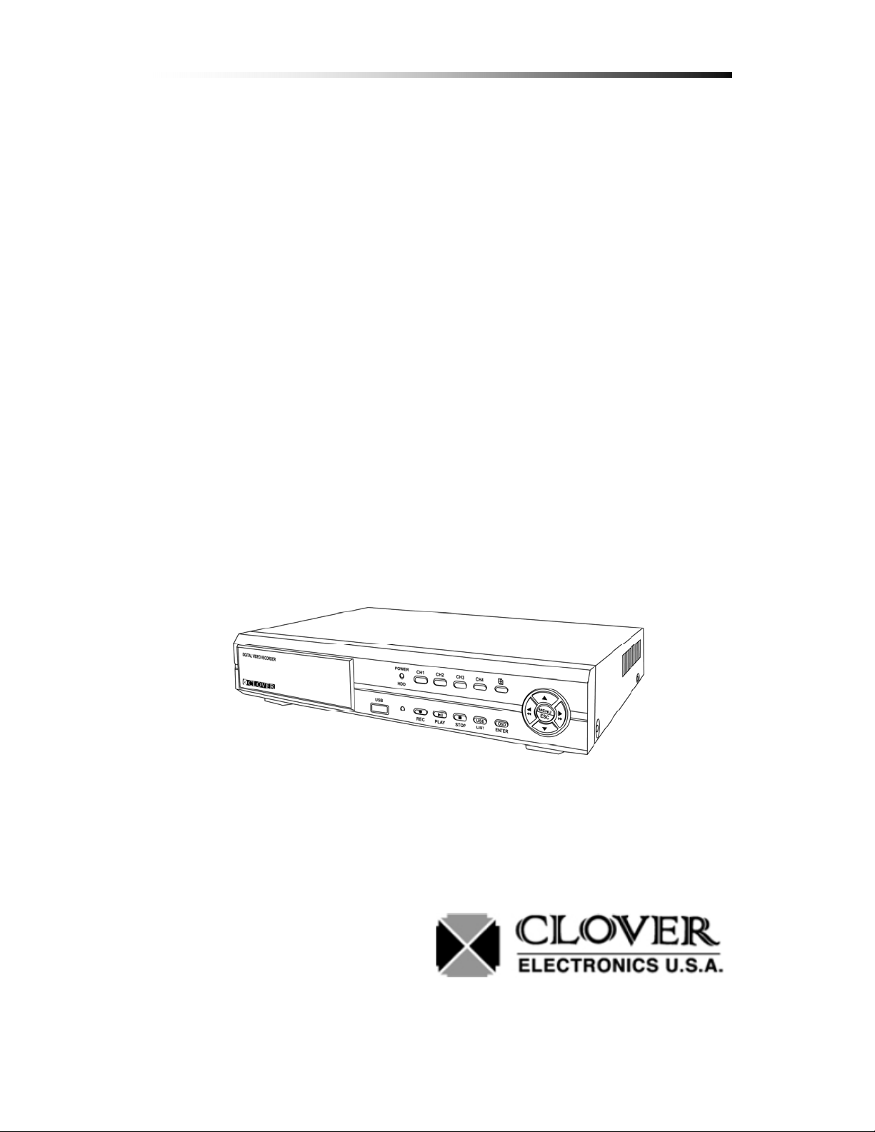
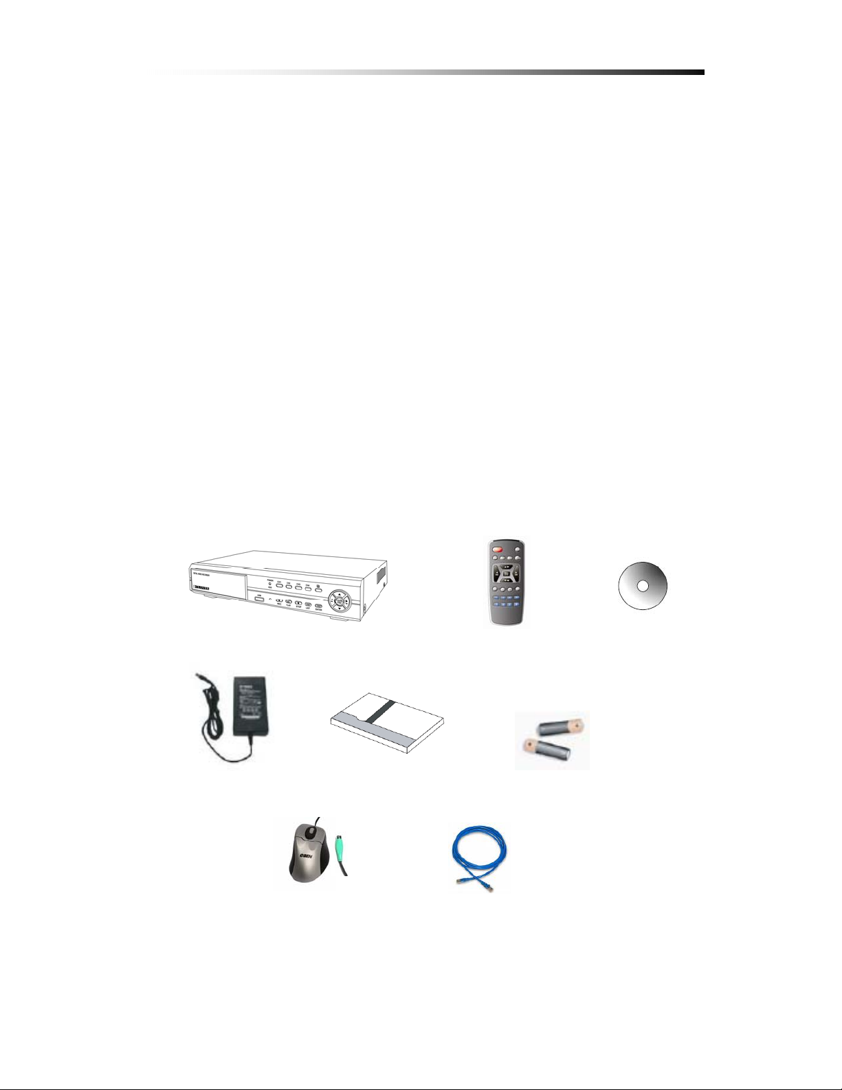
Clover CDR0430 User manual

Instruction Manual
Stand-Alone 4 Channel
Digital Video Recorder
Model CDR0430, CDR0410
Copyright ©2009 Clover Electronics U.S.A. All Rights Reserved.

Contents
- 1 -
Contents
1.Unpacking 6
About This Unit 7
2.Features 8
3.Specifications 9
4.Installation 10
4-1. What to do before Installation 10
4-2. InstallationCheckList 11
4-3. Controls and Connectors on the DVR 12
4-4. System Connection
15
4-4-1. Camera Connection 16
4-4-2. Video Output Connection / VGA Connection 16
4-4-3. Audio Connection 16
4-4-4. Network Cable Connection 17
4-4-5. Mouse Connection 17
4-4-6. Sensor Connection 17
4-4-7. Alarm Output Connection 17
4-5. Step by Step Installation 18
5.HowtoOperate 19
5-1. GeneralOperation 19
5-2. Remote Controller
20
5-3. PS/2 Mouse 22
5-4. Running for the First Time
23
5-5. Live 25
5-5-1. QuadSplitScreenDisplay 25
5-5-2. FullScreenDisplay 26
5-5-3. AutoSequenceDisplay 27

Contents
- 2 -
5-5-4. PAN / TILT & ZOOM
28
5-5-4-1. How to Connect PAN / TILT Device
28
5-5-4-2. HowtousePAN/TILT 29
5-5-4-3. How to use ZOOM / FOCUS 29
5-5-5. Toggle OSD ON/ OFF 30
5-6.Recording 31
5-6-1. ManualRecording 31
5-6-2. Automatic Recording 31
5-7.Playback 32
5-7-1. Set Playback Time 32
5-7-2. Search by Event 35
5-7-3. HowtoSearchthroughPlayback 36
5-8. CopyingtoUSB 37
6.Setup 40
6-1. SetupMenu 40
6-2. CameraSetup 41
6-2-1. Channel 42
6-2-2. Display 43
6-2-3. Camera Color Option 45
6-3. RecordSetup 46
6-3-1. Record Speed 47
6-3-2. Record Quality 49
6-3-3. HoldTime 50
6-3-4. Schedule Recording 51
6-4. Sensor 53
6-4-1. RelayOutput 54
6-4-2. Sensor Setup 55
6-5. MotionDetection 57
6-5-1. ChannelSelection 58
6-5-2. Sensitivity Selection 59
6-5-3. RelayOutputSetup 60
6-5-4. MotionAreaSetup 61
6-5-4-1. AreasetupusingDirectionkeys 62
6-5-4-2. AreasetupusingtheMouse 63

Contents
- 3 -
6-6. Screen Setup 64
6-6-1. BorderSetup 65
6-6-2. VideoAdjustment 65
6-6-3. SequenceSetup 65
6-7. Audio Setup 66
6-7-1. AudioRecordSetup 66
6-7-2. Mute Setup 67
6-7-3. Input / Output Volume Setup 67
6-8. System Setup 68
6-8-1. HardDiskSetup 68
6-8-1-1. OverwriteOption 69
6-8-1-2. FormatHDD 69
6-8-1-3. HardDiskDriveInformation 71
6-8-2. PasswordChange 72
6-8-3. TimeSet 76
6-8-3-1. TimeZoneSetup 76
6-8-3-2. TimeSetup 77
6-8-3-3. DaylightSavingOption 78
6-8-3-4. SynchronizewithNTPServer 78
6-8-4.EventList .78
6-8-5. Network Option 79
6-8-5-1. NetworkEnableOption 79
6-8-5-2. LocalIPSetup 80
6-8-5-3. PortSetup 83
6-8-5-4. MACAddressSetup 84
6-8-5-5. NetworkPassword 84
6-8-5-6. DDNSServerSetup 84
6-8-5-7. NetworkVideoQuality 84
6-8-6. RS-485 Setup 85
6-8-7.PAN/TILTDeviceSetup 86
6-8-7-1. Channel/IDSetup 86
6-8-7-2. ModelOption 86
6-8-7-3. PAN/TILTTest 86
6-8-8. Firmware Upgrade 87
6-9. Search 89
6-10. Language 89

Contents
- 4 -
6-11. Exit 89
7.Viewer 90
7-1. Installing / Running the Viewer 91
7-2. Player 92
7-2-1. Menu 93
7-2-2. Icons 94
7-2-3. HowtoOpenaVideoFile 95
7-2-4. HowtoSaveasAVIfile 96
7-2-5. HowtoCaptureaScreen 98
7-3. NetworkViewer 99
7-3-1. How to Connect to the DVR 99
7-3-2. Menu 102
7-3-3. Icons 103
Warranty Information / How to obtain Factory Service 104

Contents
- 5 -
About this manual
This is the instruction manual for the Stand-Alone type DVR, CDR0430
and CDR0410
.
This manual describes how to install and operate the DVR and provides
information regarding specifications and features of this product.
Please be sure to read this manual and follow the instructions when
installing the Digital Video Recorder.
If you have any questions or problems installing, please contact
Clover Electronics at 877-327-5000.

Contents
- 6 -
1
1.
.Unpacking
When unpacking the DVR Unit, please be cautious not to drop, throw or
hit with force. This may cause damage to the product that could lead to
malfunctions.
Before Installation please check if the following objects are included.
Stand-Alone DVR unit
Remote Controller & batteries
Instruction manual
Viewer CD
AC Adapter and screws (usage for installing HDD)
RJ-45 Cable (Not Available on CDR0410)
PS/2 Mouse (Option)
DVR Remote CD-ROM
AC Adapter Manual Batteries
ÚIf any of the above items are missing please contact Clover Electronics
PS/2 Mouse
(Option) RJ-45 Cable

Contents
- 7 -
About This Unit
You have just purchased a state-of-the-art 4 CH Stand Alone DVR with
network connection.
The most interesting feature of this system is the USB Firmware updating
option, which enables software upgrading and software management to be
done at home with a computer and a USB drive, instead of sending the
DVR.
To enhance the user friendliness of this DVR system, the user can operate
with both the remote controller and a PS2 mouse (option).
We hope you have a great experience with our product. Thank you.

Contents
- 8 -
2
2.
.Features
Triplex (Record / Playback / Live)
Real Time Full, Quad and Auto sequence Display mode
High Quality, Low Cost and Full Option System
Stand Alone Type (Non-PC, Non-OS)
Programming MENU in OSD (On Screen Display)
Built-in Time / Date Generator
Event list of 127
Motion / Alarm detection and Schedule recording
Quick Search : Date & Time / Event
Hard Disk Drive Overwrite
RS-485 Interface for PT Camera control (Option)
Multi-user network monitoring and remote DVR controlling
(up to 2 users)
Copy and Firmware Update by USB
VGA connection
MJPEG Compression
Remote Control

Contents
- 9 -
3
3.
.Specifications
Items Specifications
System Type NTSC PAL
Input 1Vp-p 75Ohm, Input BNC ¯4
VGA VGA Output ¯1
Video
Signal Output 1Vp-p 75Ohm, Input BNC ¯2
Input / Output 2 ¯RCA (1CH Input, 1CH Output)
Audio Recording Mode Mono PCM
Display Frame 60 Field per sec
(each) 50 Field per sec
(each)
Display
Display Resolution 640 ¯448 640 ¯544
Video Compression Real-Time full triplex
M-JPEG codec core
Video Resolution 640¯224 640¯272
Recording Method Continuous, Event
(Motion & Alarm detection)
Recording Field 60 Field per sec 50 Field per sec
Recording
Image File Size 3 ~ 25KB 4 ~ 27KB
Resolution 640 ¯224, 320 ¯112
Feature Real time Transmit, Remote Control
Network
Connection TCP/IP, UDP, DHCP
Playback Mode Live, Playback
Playback Screen
Mode Full, Quad
Playback
Search Search by Date / Time, Event List
External Alarm Input Alarm Input : Terminal Block 4
Alarm
Control Alarm Output Relay Out : Terminal Block 1

Contents
- 10 -
4
4.
.Installation
4-1. What to do before Installation
Make sure all the required hardware is available.
-Stand-alone DVR unit (HDD installed)
-4 Cameras (including power for each camera unit)
-CCTV or VGA monitor (or TV set)
-Network cable (for connecting to network)
Connect the cameras to the DVR unit and the DVR unit to the
monitor (video output device)
Perform HDD format at the first screen to proceed
Confirm live video is displayed on the monitor before proceeding
to the next step.
Select the Setup Menu and set the current date and time
Set values for required options such as motion detection, etc.
Be sure to setup the network on the DVR before utilizing network connection.

Contents
- 11 -
4-2.
Installation Check List
Are the cameras installed at the right position?
Are the camera cables connected to the inputs?
Is the audio cable connected to the input?
Is the system set on a stable location?
Is the placement of the system clear from any elements such as water, excess
dust, direct sunlight, magnetic field, etc…
Is the system located away from temperatures beyond 32ºF~122ºF
Is the location of the DVR unit away from the reach of children?
Are the batteries inserted correctly in the remote controller?
Is the mouse compatible with PS/2?
Is the video output cable connected to the correct jack?
Are all components (cameras, DVR) connected to the correct power supply?

Contents
- 12 -
4-3.
Controls and Connectors on the DVR
Front
ÚA
C1:Channel1(FullScreen)
C2:Channel2(FullScreen)
C3 : Channel 3(Full Screen) C4 : Channel 3(Full Screen)
ÚB
REC : To start / stop recording
Play / Pause : To start playback / pause screen
Stop : To Stop playback
List/USB : USB Copy / Display Event List
Enter/OSD : Enter Key(Menu) / OSD ON/OFF(Live)
- OSD ON/OFF BDate / Time / Memory usage Display option(Live)
LED
USB Port Remote Controller Sensor
A D
B
C

Contents
- 13 -
ÚC
Back to Quad Screen Mode & Auto Screen
- Auto Screen BDisplay each channel in full screen followed by Quad
screen for the duration set by the user.
ÚD
S: Used as Up key
T: Used as Down key
X: Used as Right key, or Fast Forward during
playbackmode
W: Used as Left key, or Rewind during
playbackmode
MENU/ESC : used to enter the Main menu or to
escape to live screen
ÚLED
Power : Red light when power is ON, turns off when power is OFF
HDD :Red
light blinks when playback mode, turns off during live mode
(blinks when recording)

Contents
- 14 -
Rear
ÚA
Alarm Input : The user can connect to ports 1 ~ 4.
Grounding : All alarm input must be connected to this grounding port.
Alarm Output : Connect one line to “COM” and the other to either
Normal Open(N.O) or Normal Close(N.C) according
to system setup
Video output device port
Camera Input port VGA Port
Network connection port
DC 12V adaptor port
Audio connection port PS/2 Mouse port A
RS485
Alarm output
Grounding
Alarm Input

Contents
- 15 -
4-4.
System Connection
Input
Output
Input / output
Network

Contents
- 16 -
4-4-1. Camera Connection
Connect the cameras to the Video Input (BNC Connector) on the
back of the unit as shown.
On this unit, the user can connect up to 4 Cameras.
4-4-2. Video Output Connection / VGAConnection
Connect the composite monitor to any one of the BNC ports.
This unit can support up to two composite monitors at the same time.
The video output to the two monitors will be the same.
Connect the VGA Monitor’s connector to the “DSUB 15 Pin
Connector” on the rear of the unit.
The Video Output from the VGA port has the same content as the output from the BNC
port, but the quality of the video stream will be better.
4-4-3. Audio Connection
Connect the speaker and audio input line to this port.
This unit can only support one audio input.

Contents
- 17 -
4-4-4. Network Cable Connection (Not Available on CDR0410)
Our Network Cable Connector is designed for RJ45 type cables.
Connect the Network cable here to utilize the network function of the DVR
4-4-5. Mouse Connection
This port is designed for PS/2 devices.
Connect the mouse here to utilize the device in the DVR system
4-4-6. Sensor Connection
The DVR unit has 4 Input ports for Sensors.
.
To connect, press the trigger to open the socket
ÚNote : the trigger may be difficult to press.
4-4-7. Alarm Output Connection
To connect Alarm Output, Connect one end of the cable to the
Common socket (COM) and the other to either Normal
Open(N.O) depending on system setup.
Like the Sensor Connection (Refer to 4-3-6), the trigger must
be pushed to insert the cable.
trigger trigger
trigger

Contents
- 18 -
4-5.
Step By Step Installation
Set Cameras in position
Set Audio Input device in position
Set Sensor device in position
Set DVR unit in position.
ÚNote : The DVR unit must use the 12V adaptor that comes with the set.
Usage of other adaptors may cause malfunction.
Connect DVR unit with the Cameras, Audio Input device and Sensors.
Connect a VGA monitor or (and) a composite monitor to the DVR unit.
Check if the Video Output and Audio Output are clear. If there is a problem
after correct setup, please contact Clover Electronics.
If you wish, you may connect the DVR unit with a PS/2 mouse.
Connect the DVR unit to the network using the standard RJ45 type network
cable.
Check the remote controller for correct installation of batteries.
Contact Clover Electronics for Latest Firmware update.
You are good to go!!! (Check 4-4. System Connection)

Contents
- 19 -
5
5.
.How to Operate
5-1.
General Operation
You can operate the functions of the system by using the buttons located at the
front panel of the DVR unit, as well as the remote controller and a PS/2 mouse.
The system status is indicated by either the LED lights located near the center
of the front panel, or the monitor.
This system is protected from pressing the buttons by accident, but be careful
when using the “Hard Disk Setup” option, for this may lead to data loss, and
the “Password Change” option. (If you forget your password, please contact
Clover Electronics for help)
This manual suits for next models
1
Table of contents
Other Clover DVR manuals

Clover
Clover CDR-1610 User manual

Clover
Clover CDR-4070 User manual

Clover
Clover HDV043 User manual

Clover
Clover DV1670 User manual

Clover
Clover C1704DVR User manual

Clover
Clover CDR-0850 User manual

Clover
Clover CDR-4170 User manual

Clover
Clover DVR 1600 User manual

Clover
Clover DV1630 User manual

Clover
Clover CDR-4770 User manual

Clover
Clover CDR-4770 User manual

Clover
Clover CDR 0440 User manual

Clover
Clover CDR-4170 User manual

Clover
Clover CDR-4015 User manual

Clover
Clover CDR-4010 User manual

Clover
Clover LCD2084 User manual

Clover
Clover DV0890 User manual

Clover
Clover CDR1660 User manual

Clover
Clover CDR-1650 User manual

Clover
Clover CDR4450 User manual