CLP Clevertronics Ultrablade Pro Instruction Manual
1943062
V1.3
27 May 2021
UK Instruction Sheet Template – V1.1 – Updated: 20/11/2020
Zoneworks, HIVE and DATA Monitored Options
Fittings with part numbers -ZW, -HVG, -DATA are fitted with Zoneworks communications modules
(nodes). These fittings are monitored using either Powerline Carrier Technology that utilize the power
cable to provide data communication, RF transceiver modules operating in the ISM band or a dedicated
data cable to/from data routers installed on a dedicated data trunk connected to a central Server (can also
be connected via Ethernet/Internet/Fibre). Zoneworks software on the server is used to monitor,
coordinate testing and collate test data from each fitting. Zoneworks Fittings can be commissioned by a
single push of the test switch or by scanning the supplied barcode. The LED Test Switch indicator provides
a multifunction indication of the status of the fitting during testing and normal operation:
Option
State
LED Operation
ZW, HVG, DATA
Commissioned
LED on Solid (Green)
ZW, DATA Un-commissioned
Batt plugged-in: yellow 1s, green 1s
Batt unplugged: red 1s, off 1s
HVG Un-commissioned
With network connectivity
Batt plugged-in: yellow 1s, green 1s
Batt unplugged:
red 1s, off 1s
HVG Un-commissioned
Without network connectivity
Batt plugged-in: yellow 250mS, green
250mS, yellow 250mS, green 250mS,
green 1s
Batt unplugged: red 250mS, off
250mS, red 250mS,off 250mS, off 1s
ZW, DATA
Emergency Light Test In Progress
LED flashes at yellow 5s , 0ff 1s
HVG
Emergency Light Test In Progress
LED flashes at yellow 1s , 0ff 1s
In the case of the DATA version a 2-way “figure 8” cable and terminal block facilitates the connection to
the DATA network via a multi-drop bus (daisy chain connection). For further information of installation of
a Zoneworks system, please refer to the Zoneworks Users Guide and Commissioning Guide (incl. DATA
version)
DALI EM Option
Luminaires with part numbers having -DALI are fitted with DALI modules (nodes) that facilitate connection
and integration to 3rd Party Lighting Control Systems. Before installing the -DALI fitting please confirm
that the Lighting Control System has the capability to monitor DALI Emergency Luminaires. The -DALI
fitting will be addressed and configured into the control system by the Lighting Control System
Commissioning Technicians and not Clevertronics.
State
LED Operation
Commissioned/ Un-commissioned LED on Solid (Green)
Emergency Light Test in progress
LED flashes at 1s On (Yellow) & 1s Off
“IDENTIFY COMMAND” Fitting goes into emergency mode for 10 seconds
A 2-way “figure 8” cable and terminal block facilitates the connection to the DALI network OR a 5/6way
“structured wiring system” lead and plug facilitating the power and DALI connection. DALI connections
are marked as Da Da.
Clevertest and Clevertest Plus
Refer to the supplementary operation guide supplied with the Product.
After Power ON, the Status LED on a Clevertest Plus enabled fitting will display a rapid Green or Red
flashing for a period up to 2 minutes.
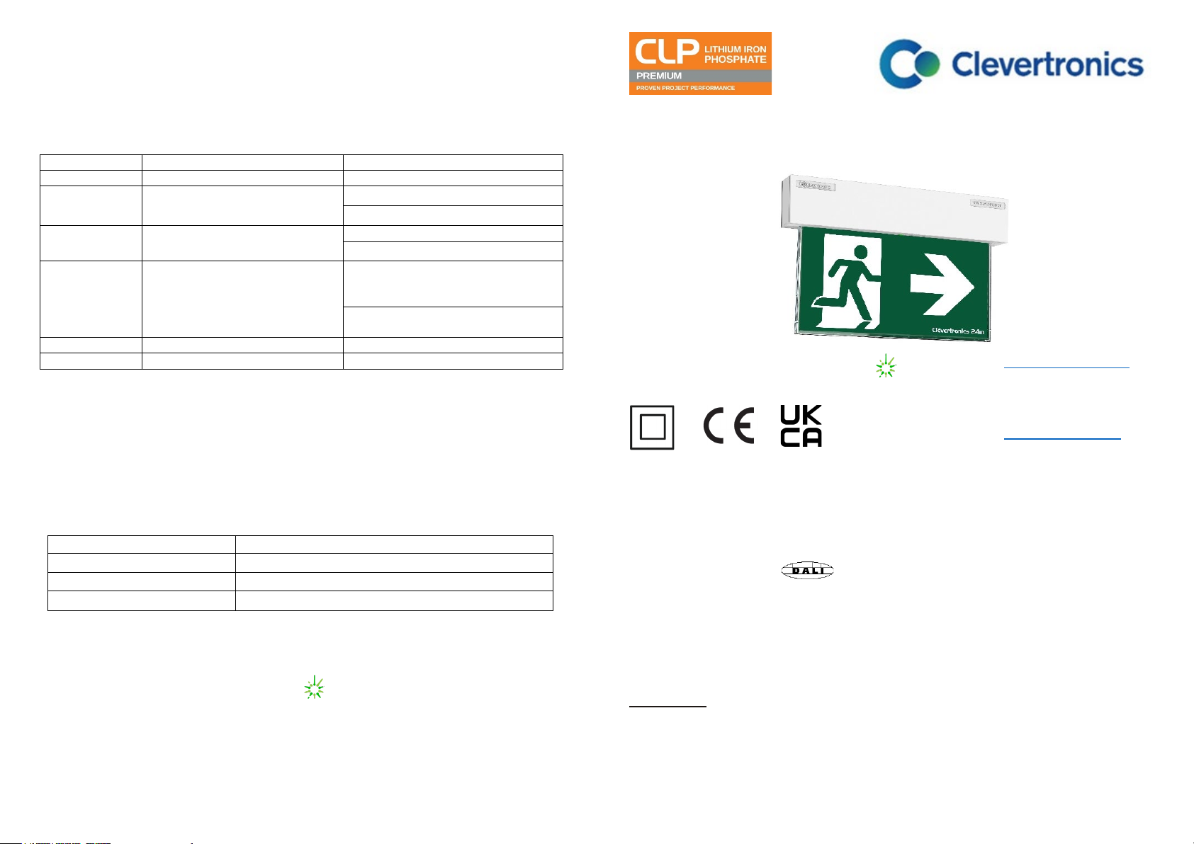
CLP™ Ultrablade Pro Surface Mount LED Exit
Installation & Maintenance Instruction Leaflet
NOTE: Standard product codes with this symbol
are enabled with Clevertest Plus capability. Please refer to the
operation guide supplied with the product for details.
Australia (Head Office)
Website: www.clevertronics.com.au
Email: info@clevertronics.com.au
Phone: +61 3 9559 2700
Fax: +61 3 9559 2799
IP20
UK OFFICE
Website: www.clevertronics.co.uk
362 Stockley Close
West Drayton UB7 9BL
Phone: 01895 430 255
Models:
CUBPRO-SM-xx-yy
Testing Options:
Options:
Manual Test
xx = Blank
Colour, Black
yy = BLK
Zoneworks
xx = ZW
Z/W DATA
xx = DATA
DALI
xx = DALI
Hive
xx = HVG
Spare Parts:
1550030
BATT:LP 3.2V 3200mAh 260mm lead,noBRKT.
8002178
LED strip PCB Assy (CT10602-Dx)
8003137
LED Driver PCA: CUBPRO-SM UK Driver, CT10142-L9, OWC
Important:
It is illegal for anyone, except for a licensed electrician to install or maintain this product. Before installation,
ensure that the electricity supply has been switched off and isolated. Installation must be carried out in
accordance with the relevant British Standards.

1943062
V1.3
27 May 2021
UK Instruction Sheet Template – V1.1 – Updated: 20/11/2020
Installation:
The CLP Ultrablade Pro Surface Mount LED Exit is a surface mount fitting. It can be attached directly to
any solid surface. Please follow the steps below to install the CUBPRO-SM Exit:
•Open the fitting using the 2 screws on either side of the blade.
•Locate the mounting surface.
•Drill holes in the mounting base to suit the mounting method, Ceiling or Wall (see images below).
•Use the mounting bracket to mark-out the mounting holes for Ceiling or Wall Mount.
•Drill power access hole as required.
•Mount the fitting using appropriate fixings.
•Route the power to the mains connection and connect the 240VAC supply.
•Attach the blade assembly to the bracket and tighten the 2 mounting screws.
•Apply power to the fitting and test.
•This luminaire contains non-user replaceable light source and battery.
•If the CTP capabilities are activated, please affix the CTP Status Label to a visible surface and add
F to marking label to show AFG.
Changing EXIT Legend Inserts
:
The Ultrablade Pro Exit comes with an assortment of standard legends.
1. To remove the legend, grasp the centre of the bottom trim piece and pull down slightly to expose the legend
edge. See photo.
2. Grasp the bottom edge of the legend and slide the existing legend out of the blade, while working the edges
out along the sides.
3. Slide the new legend into the blade, ensuring to fit the edges into the sides then slide the legend to the top
of the blade. Insert one bottom corner then the other. Slide the legend down into the bottom trim.
Note:
This luminaire (with reinforced insulation between control/LED terminal and AC supply) contains non-user
replaceable light source and battery - to be replaced (if required, refer installation instructions for battery
replacement) by Clevertronics service personnel/agents or a registered electrician.
Battery Replacement:
1. Prior to any work, isolate the power to the luminaire that requires battery replacement
2. Open the fitting using the 2 screws on either side of the blade and slide out fitting.
3. Remove the Battery Connector from the Emergency Driver.
4. Remove the battery.
5. Replace battery, securing into battery compartment, and connect to Emergency Driver.
6. Refit fitting and secure the 2 screws on either side.
LED Lamp Replacement:
1. Prior to any work, isolate the power to the luminaire that requires battery replacement
2. Open the fitting using the 2 screws on either side of the blade and slide out fitting.
3. Remove the Battery Connector from the Emergency Driver.
4. Remove the screw holding the driver PCA. Remove the PCA.
5. Remove the 4 screws holding the battery bracket. Remove the bracket with the battery.
6. Disconnect the signal cable from LED strip.
7. Remove 4 self-tapping screws and unclip the LED strip.
8. Install the new LED strip following the above procedure in reverse.
Testing Procedure:
When the unit is connected to the un-switched active, it must be allowed to charge the battery for at
least 24 hours. Conduct the following tests:
•The emergency lamp must illuminate for at least 180 min after disconnection from the mains. If the
unit fails to illuminate for the requisite time, remedial action must be taken to repair the situation
and once completed, the unit must pass a subsequent test.
•Press and hold Test Button or switch Off Mains Supply, check that the emergency lamp is On.
•Release the Test Button or Switch ON Mains Supply, check that the emergency lamp is Off (Non-
maintained operation).
Trouble Shooting:
Below are a list of common problems and their possible causes.
Fault: The Green LED Test Switch indicator is not illuminated.
Check: A.C. is connected and is turned on.
Battery is connected
Test Switch for damage.
Fault: Lamp does not illuminate in emergency mode.
Check: A.C. is connected.
Lamp is correctly inserted.
Battery is connected
Fault: Lamp illuminates in emergency mode, but only stays on for a short period.
Check: Battery has been allowed to charge for at least 24 hours.
Battery for damage
Caution:
On many building sites, power circuits may be cut off in an uncontrolled and repetitive basis during
construction. As a result, any Exit & Emergency Units, on these circuits, will have their batteries
discharged or “cycled”. The Li-ion battery in the luminaire has been selected to give excellent long life
performance in a controlled IEC 60598-2-22 testing environment. Excessive battery cycling will reduce
through-life performance and may lead to premature battery failure. Battery warranty claims, as a result
of such abuse, are specifically EXCLUDED from Clevertronics warranty terms.
Warranty:
For Product Warranty information and Terms and Conditions of Sales please refer to our website
https://clevertronics.co.uk/product-warranty-statement/
Ceiling Mounting Points (4)
Wall Mounting Points (2)
Power Connections Power Access


