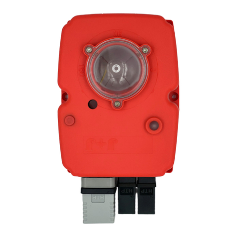
J4C BSR KIT J4C 20 User manual

INDEX/ÍNDICE
(EN)
MOUNTING INSTRUCTIONS BSR KIT
J4C 20 TO 85
(ES)
INSTRUCCIONES MONTAJE KIT BSR
J4C 20 A 85
(EN)
MOUNTING INSTRUCTIONS BSR KIT
J4C 140 TO 300
(ES)
INSTRUCCIONES MONTAJE KIT BSR
J4C 140 A 300
.....................................................................................................................................................................
2
.....................................................................................................................................................................
5
............................................................................................................................................................
8
............................................................................................................................................................
11
MOUNTING INSTRUCTIONS BSR KIT V 22/06

BSR KIT J4C 20 TO 85
(EN)
ASSEMBLY INSTRUCTIONS
The BSR safety block system is an automasm
that, when coupled to the J4C mul voltage
electric actuators, lets the valve situate in a
preferable posion NC or NO, when there is a
power supply failure. Inside of the housing there
are a BSR print circuit board and a baery pack,
which is kept in connuous charge.
In case of the valve is not in the preferable
posion and there is a power supply cut, the BSR
system returns the valve back to the preferable
posion by means of the baeries tension,
operang as a “single acng” actuator.
02
INDEX
OUTSIDE BOX INSIDE BOX

03
INDEX
ENGLISH -
ASSEMBLY INSTRUCTIONSBSR KIT 20/85
ENGLISH -ENGLISH -
ASSEMBLY INSTRUCTIONS
VERY IMPORTANT:
PLEASE, FOLLOW THESE INSTRUCTIONS STEP BY STEP. IF THE CONNECTOR OF THE BATTERY PACK IS PLUGGED INTO
THE "BSR" PCB, BEFORE ARRIVING TO POINT 7, THE PCB COULD BE DAMAGED.
KIT COMPONENTS
Element A - 1 BSR PCB.
Element B - 1 Lower baery support.
Element C - 1 Baery pack.
Element D - 1 Upper baery support.
Element E - 3 Sheet metal Fixing screws
Element F - 2 Plasc Fixing screws
A
BC D
EF
* Fill in the document inside the kit, and send it to the fax number (93 871 32 72) or e-mail: in[email protected]om, shown in the document.

Take the BSR PCB (Element A) from the KIT and connect it to the
actuator PCB, by using the connector shown in the picture.
Fix it to the actuator metal plate, by using the Sheet metal
fixing screw (Element E).
2 3
1
Remove the screw, which is fixing the
hand wheel. Remove the 6 screws between the
cover and the body of the actuator.
Carefully li the cover.
5
4
Place the baery pack (Element C) on the lower baery support (Element B) (Fig.7B).
The baery cables should remain on the boom part.
Put the cables, as shown in the picture (Fig.7A).
Connect the baery cables to the BSR PCB (Element A), as per (Fig.7C).
Put the lower baery support (Element B). See (Fig.6A).
Fix it by using 2 Sheet metal fixing screws (Element E)
(Fig.6B & 6C).
Place the upper baery support and fix it to the columns of the
lower baery support (Element B), by using the Plasc fixing
screws (Element F).
68
A
B
C
7
B
C
A
BSR Configuraon NO or NC:
NC (normally close) SELDIR jumper ON.
NO (normally open) SELDIR jumper OFF.
Fix the cover to the body by using the 6 screws.
Carefully mount the cover, minding the cables
not to be pressed.
Mount the hand wheel on the sha and fix
it by using the screw.
15 17
16
9
SELDIR jumper
04
INDEX

BSR KIT J4C 20 A85
(ES)
INSTRUCCIONES DE MONTAJE
El sistema de seguridad BSR es un automasmo que,
incorporado a los actuadores J4C permite, en caso
de interrupción de la alimentación eléctrica, situar
la válvula en posición preferente predeterminada
NC o NC.
En el interior del actuador se encuentra situada la
tarjeta del circuito BSR más el bloque de baterías que
se encuentra en carga connua, lo que permite accio-
nar el actuador, en caso necesario, cuando la unidad
detecta un fallo de suministro eléctrico.
Hay que tener en cuenta que no se trata de un actua-
dor “simple efecto” , pero que en caso de que la válvu-
la se encuentre en posición no preferente, el sistema
BSR, mediante las baterías, accionará la válvula hasta
situarla en la posición predeterminada como prefe-
rente, actuando como un actuador “simple efecto”.
EXTERIOR CAJA INTERIOR CAJA
05
INDEX

06
INDEX
ESPAÑOL
INSTRUCCIONES DE MONTAJE KIT BSR 20/85
-
AVISO MUY IMPORTANTE:
SEGUIR PASO A PASO ESTAS INSTRUCCIONES. SI EL CONECTOR DE LA BATERIA ESTA CONECTADO A LA ELECTRÓNICA
DEL BSR, ANTES DE LLEGAR AL PUNTO 7, LA ELECTRÓNICA PUEDE DAÑARSE.
COMPONENTES DEL KIT
Pieza A - 1 Electrónica BSR
Pieza B - 1 Soporte inferior batería
Pieza C - 1 Batería.
Pieza D - 1 Soporte superior batería
Pieza E - 3 Tornillos rosca chapa
Pieza F - 2 Tornillos rosca plásco
A
BC D
EF
* Rellenar el documento adjunto al KIT y enviarlo al número de fax (93 871 32 72) o por e-mail: [email protected]om

Enchufar la electrónica BSR (
Pieza A
) a la electrónica del
actuador mediante el conector señalado en la figura.
Encajar la batería (
Pieza C
) en el soporte inferior batería (
Pieza B
) (Fig. 7B). Los cables
de la batería deben quedar en la parte inferior. Situar los cables según imagen (Fig. 7A).
Conectar los cables de la batería a la electrónica BSR (
Pieza A
) (Fig. 7C).
Situar el soporte inferior de la batería (
Pieza B
) según imagen
(Fig. 6A) y fijarlo mediante 2 tornillos rosca chapa (
Pieza E
)
(Fig. 6B y 6C).
Colocar el soporte superior batería (
Pieza D
) y fijarlo a las columnas
del soporte inferior batería (
Pieza B
) mediante 2 tornillos rosca
plásco (
Pieza F
) (Fig. A y B).
Configuración del BSR NO o NC (Fig.9):
NC (normalmente cerrado) jumper SELDIR conectado.
NO (normalmente abierto) jumper SELDIR desconectado.
Fijar la eletrónica a la chapa metálica del actuador, mediante
un tornillo rosca chapa (
Pieza E).
6
9
78
B
C
A B
2 3
1
Desatornillar el tornillo que fija el
volante y rerarlo.
Desatornillar los 6 tornillos de unión
entre la tapa y el cuerpo.
Separar la tapa de la base del actuador,
para poder instalar el kit
Atornillar los 6 tornillos que unen la tapa
al cuerpo del actuador.
Montar la tapa, con cuidado de no aprisionar
los cables.
Situar el volante en el eje del actuador y fijarlo.
15 17
16
A
B
C
A
SELDIR jumper
5
4
07
INDEX

BSR KIT J4C 140 TO 300
(EN)
ASSEMBLY INSTRUCTIONS
The BSR safety block system is an automasm
that, when coupled to the J4C mul voltage
electric actuators, lets the valve situate in a prefe-
rable posion NC or NO, when there is a power
supply failure. Inside of the housing there are a
BSR print circuit board and a baery pack, which is
kept in connuous charge.
In case of the valve is not in the preferable
posion and there is a power supply cut, the BSR
system returns the valve back to the preferable
posion by means of the baeries tension, opera-
ng as a “single acng” actuator.
08
INDEX
OUTSIDE BOX INSIDE BOX

09
INDEX
ENGLISH -
ASSEMBLY INSTRUCTIONSBSR KIT 140/300
ENGLISH -ENGLISH -
ASSEMBLY INSTRUCTIONS
VERY IMPORTANT:
PLEASE, FOLLOW THESE INSTRUCTIONS STEP BY STEP.IF THE CONNECTOR OF THE BATTERY PACK IS PLUGED
TO THE “BSR” PCB, BEFORE ARRIVING TO POINT 4, THE PCB COULD BE DAMAGED.
KIT COMPONENTS
Element A- 1 BSR PCB.
Element B-
Element C
Element D- 3Sheet metal Fixing screws
Element E -
A
B
D
E
C1
Connect 1
Connect 1
Connect 2
C2
Connect 2
* Fill in the document inside the kit, and send it to the fax number (93 871 32 72) or e-mail: inf[email protected], shown in the document.

Put both battery cables
(
Element
C) together with the plastic clamp
(
Element E)
(Fig. 8D).
Cut the remaining part of the plastic clamp
(
Element E).
BSR Configuraon NO or NC:
NC (normally close) SELDIR jumper ON.
NO (normally open) SELDIR jumper OFF.
Fix the 8 screws, between the cover and
the body.
Carefully replace the cover and be sure that
the joint is correctly lodged in its place.
Be sure that any cable is not trapped between
the cover and the body.
Reassemble the hand wheel and fix it with
the screw.
11 12
SELDIR
jumper
10 13
23
15
Remove the hand wheel screw and
takeitoff.
Remove the 8 screws between the
cover and the body of the actuator.
Carefullyremove the cover, in order to
install the kit.
Take the BSR PCB
(Element B)
from the KIT and connect it to
the actuator PCB, by using the connector shown in the picture.
Fix it to the actuator metal plate, by using the Sheet metal
fixing screw
(Element D).
4
Fix the baery supports (
Element
B), with the sheet metal
fixing screws (
Element
D). Connect the baery cables to the
BSR PCB (
Element
A), as per (
Element
C).
8
69
AA
B
B
Place the 2 baery packs
(Element C)
as per picture (Fig. A& B). Place the 2 baery supports
(Element B)
as per picture (Fig. A& B).
7
A
C1 C2
Connect 1
Connect 2
Place the baery cables so as they remain over
the baery pack (fig. 7A).
Connect the C1 baery cable to connect 1.
Connect the C2 baery cable to connect 2.
10
INDEX

BSR KIT J4C 140 A300
(ES)
INSTRUCCIONES DE MONTAJE
El sistema de seguridad BSR es un automasmo que,
incorporado a los actuadores J4C permite, en caso de
interrupción de la alimentación eléctrica, situar la válvu-
la en posición preferente predeterminada NC o NO.
En el interior del actuador se encuentra situada la
tarjeta del circuito BSR más el bloque de baterías que,
se encuentra en carga connua, lo que permite accio-
nar el actuador, en caso necesario, cuando la unidad
detecta un fallo de suministro eléctrico.
Hay que tener en cuenta que no se trata de un actua-
dor “simple efecto” , pero que en caso de que la válvula
se encuentre en posición no preferente, el sistema
BSR, mediante las baterías, accionará la válvula hasta
situarla en la posición predeterminada como preferen-
te, actuando como un actuador “simple efecto”.
11
INDEX
EXTERIOR CAJA INTERIOR CAJA

12
INDEX
ESPAÑOL
INSTRUCCIONES DE MONTAJE KIT BSR 140/300
-
AVISO MUY IMPORTANTE:
SEGUIR PASO A PASO ESTAS INSTRUCCIONES. SI EL CONECTOR DE LA BATERIA ESTA CONECTADO A LA ELECTRÓNICA
DEL BSR, ANTES DE LLEGAR AL PUNTO 4, LA ELECTRÓNICA PUEDE DAÑARSE.
COMPONENTES DEL KIT
Pieza A - 1 Electrónica BSR
Pieza B- 2 Soportes batería
Pieza C - 2 Baterías
Pieza D- 3 Tornillos rosca chapa
Pieza E -1 Brida plásco
A
B
D
E
C1
Connect 1
Connect 1
Connect 2
C2
Connect 2
* Rellenar el documento adjunto al KIT y enviarlo al número de fax (93 871 32 72) o por e-mail: [email protected]om

Enchufar la electrónica BSR (
Pieza A
) a la electrónica del
actuador mediante el conector señalado en la figura.
Fijar los cables de las 2 baterías (
Pieza C
) mediante la brida de plásco (
Pieza E
).
Cortar el trozo de brida de plásco (
Pieza E
) sobrante.
Configuración del BSR NO o NC:
NC (normalmente cerrado) jumper SELDIR conectado.
NO (normalmente abierto) jumper SELDIR desconectado.
Fijar la electrónica a la chapa metálica del actuador,
mediante un tornillo rosca chapa (
Pieza D
).
23
1
Desatornillar el tornillo que fija el
volante y rerarlo
Desatornillar los 8 tornillos de unión
entre la tapa y el cuerpo.
Separar la tapa de la base del
actuador, para poder instalar el kit.
Atornillar los 8 tornillos que unen la tapa al
cuerpo del actuador.
Montar la tapa, con cuidado de no aprisionar
los cables.
Situar el volante en el eje del actuador y fijarlo.
11 12
45
SELDIR
jumper
10 13
Situar las dos baterías (
Pieza C
) según imagen (Fig. 6A y 6B). Situar los cables por la parte posterior de las baterias.
Conectar Bateri C1 en connect 1.
Conectar Bateri C2 en connect 2.
Situar los dos soportes batería (
Pieza B
) según imagen. Fijar los soportes batería (
Pieza B
) mediante dos tornillos rosca
chapa (
Pieza D
).
Conectar los cables de la batería a la electrónica BSR (
Pieza A
)
(Fig. 8C).
8
679
A
B
A B
C
C1 C2
Connect 1
Connect 2
13
INDEX
This manual suits for next models
2
Table of contents
Languages:
Other J4C Safety Equipment manuals
Popular Safety Equipment manuals by other brands

ABS
ABS ABS-Lock X-SR-HD installation manual

Spinlock
Spinlock DECKVEST LITE instructions

Honeywell
Honeywell Miller AirCore Series User instruction manual supplement

Mueller
Mueller SENTRYX SUPER CENTURION installation instructions

LAHTI PRO
LAHTI PRO L4160200 User instructions

Cattron
Cattron DYNAGEN RA400 Installation and user manual