Page 2
CAUTION! DO NOT LOOK DIRECTLY AT THESE LEDS WHILE THEY ARE ON.
MOMENTARY BLINDNESS AND/OR EYE DAMAGE COULD RESULT!
IMPORTANT WARNING!
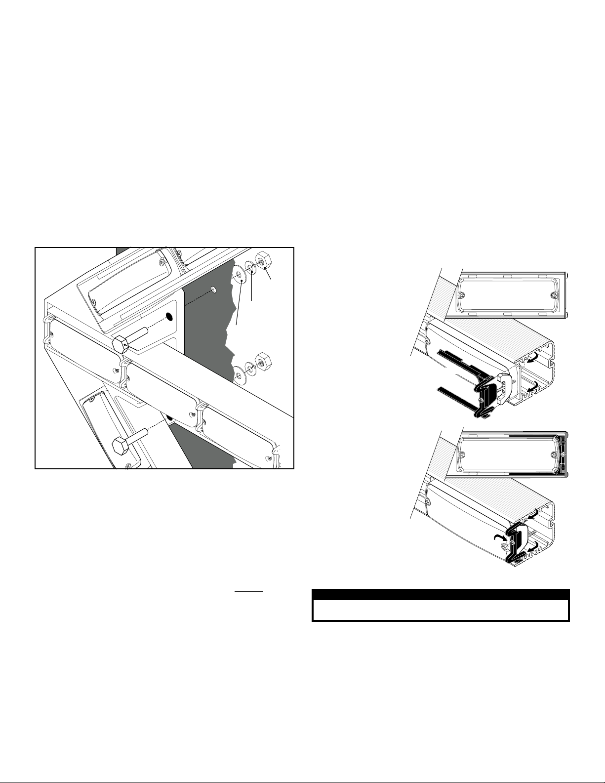
MOUNTING
SURFACE
3/8-16
HEX NUT
3/8 FLAT
WASHER
3/8 SPLIT
LOCK
WASHER
3/8-16 X 2 HEX
HEAD BOLT
3/8-16 X 2 HEX
HEAD BOLT
FIG. 1
Installation:
Caution: Permanent mounting of this product will require
drilling. It is absolutely necessary to make sure that no other
vehicle components could be damaged by this process. Check
both sides of the mounting surface before starting. If damage is
likely, select a different mounting location.
IMPORTANT: It is the responsibility of the installation technician
to make sure that the installation and operation of this product
will not interfere with or compromise the operation or efficiency
of any vehicle equipment!
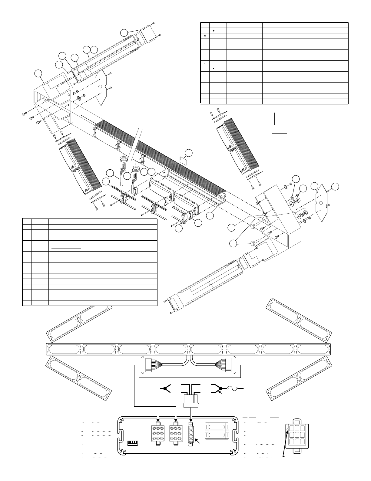
1. Place the Traffic Advisor™ in its mounting position on the
mounting surface, making sure the arrow is level. Mark the 4 bolt
locations off onto the mounting surface (2 bolts per side).
2. Remove the Traffic Advisor from the mounting surface and drill
the 4 mounting holes using a drill sized for the 3/8” bolts.
3. Install the mounting hardware onto the bolts in the order shown
and mount the Traffic Advisor to the vehicle (Fig. 1).
IMPORTANT: When you are routing wires, the existing, factory
wire harness should be followed whenever possible. The
existing harness has been positioned so no wires will be
damaged by vehicle operation. The factory harness may include
a service loop that will keep the wires from being damaged or
broken by the movement of the dump body.
Wiring:
WARNING! All customer supplied wires that connect to the
positive terminal of the battery must be sized to supply at least
125% of the maximum operating current and FUSED at the
battery to carry that load. DO NOT USE CIRCUIT BREAKERS
WITH THIS PRODUCT!
Wire Connections:
1. Splice the 2 RED wires together, then extend this single wire to
the battery and install a 15 amp fuse block (customer supplied) to
the end of the wire. (remove the fuse before connecting any
wires to the battery) Connect the wire to the POSITIVE (+)
battery terminal. Refer to the wiring diagram on the next page.
IMPORTANT: There must not be more than 2 feet of wire between
fuse block and battery. The wire between fuse and battery is
unprotected, do not allow this wire to come in contact with any
other wires.
2. Splice the 2 BLACK wires together, then extend this single wire
to the battery and connect it to the battery ground. If your vehicle
has a cable extending from the negative terminal of the battery to
the chassis, it is best to attach the BLACK wire at the chassis
connection.
Operation:
The operation of this TA is controlled by the TACTL3A Traffic
Advisor control head. Refer to the instructions that come with
the control head for operation.
Service:
This section shows you
how to access the
lightbar for service or
lighthead replacement.
To replace a lighthead,
first loosen the set
screw(s) on the bracket.
Now squeeze the clip
together so that it
disengages from the
extrusion and pull the
bracket straight out.
With the bracket
removed the lighthead
lifts out and can be
unplugged from the
harness and removed
from the lightbar.
IMPORTANT! Before
returning the vehicle
to active service,
visually confirm the
proper operation of
this product, as well as
all vehicle
components/
equipment.
Snap the
bracket into
the extrusion.
The bracket mounts
as shown. Tighten the set
screw on the bracket to secure it.
FRONT VIEW
FRONT VIEW
Place lighthead
into extrusion
Snap-InSnap-In
Snap-InSnap-In
Tighten Set Screw