CM 637 Series User manual

OPERATING,
MAINTENANCE &
PARTS MANUAL
MANUALLY LEVER
OPERATED
CHAIN HOIST
Manual No. 637-E
Before installing hoist, fill in the
information below.
Rated Load __________________
Serial No. ____________________
Purchase Date _______________
37700C
Rated Loads:
3/4, 1-1/2, 3, 6 tons
(750, 1500, 3000 and
6000kg.)
Follow all instructions and warnings for
inspecting, maintaining and operating this hoist.
The use of any hoist presents some risk of personal
injury or property damage. That risk is greatly
increased if proper instructions and warnings are not
followed. Before using this hoist, each operator
should become thoroughly familiar with all warnings,
instructions and recommendations in this manual.
Retain this manual for future reference and use.
Forward this manual to operator.
Failure to operate equipment as directed
in manual may cause injury.
SERIES 637
®

1
CM
HOIST
PARTS
AND
SERVICES
ARE
AVAILABLE
IN
THE
UNITED
STATES
AND
IN
CANADA
As a
CM
Hoist user, you are assured of reliable repair and parts services through a
network of Master Parts Depots and Service Centers that are strategically located
in
the
United States and Canada. These facilities have been selected
on
the basis of their
demonstrated ability to handle all parts and repair requirements promptly and efficiently.
To
quickly obtain the name of the Master Parts Depot or Service Center located nearest
you, call (800) 888-0985. Fax: (716) 689-5644.

SAFETY
PRECAUTIONS
Each
CM
Series 637 Lever Operated Hoist
is
built
in
accordance with the specifications contained herein and at
the time of manufacture complies with our interpretation of applicable sections of the * American Society of
Mechanical Engineers Code 830.21 "Manually Operated Lever Hoists".
The safety laws for elevators and for dumbwaiters may specify construction details that are not necessarily
incorporated
in
CM
industrial hoists. We recommend the use of equipment that meets state and national safety
codes. Columbus McKinnon Corporation cannot be responsible for applications other than those for which
CM
equipment
is
recommended.
A THIS SYMBOL POINTS OUT IMPORTANT SAFETY INSTRUCTIONS WHICH IF NOT FOLLOWED A
COULD ENDANGER THE PERSONAL SAFETY AND/OR PROPERTY OF YOURSELF AND OTHERS.
READ AND FOLLOW ALL INSTRUCTIONS
IN
THIS MANUALAND ANY PROVIDED WITH THE
EQUIPMENT BEFORE ATTEMPTING TO OPERATE YOUR CM SERIES 637 LEVER HOIST.
'Copies
of
this standard
can
be
obtained from ASME Order Department,
22
Law Drive, Box 2300, Fairfield,
NJ
07007-2300, U.S.A.
DO'S
AND
DO
NOT'S
Safe Operation of Hoists
The following are Do's and
Do
Not's for safe operation of
Hoists. Taking precedence over any specific rule listed
here, however,
is
the most important rule of all, USE
COMMON SENSE. A few minutes spent reading these
rules can make
an
operator aware of dangerous practices
to avoid and precautions to take for his own safety and
the safety of others. Frequent examinations and periodic
inspections of the equipment as well
as
a conscientious
observance of safety rules may save lives as well as time
and money.
1.
DO
read ASME 830.21, HST-3M and this
Manual thoroughly.
2.
DO
be
familiar with the Hoist operating controls,
procedures and warnings.
3.
DO
make sure the suspension hook
is
securely
attached to a suitable support.
4.
DO
maintain firm footing or
be
otherwise secure
when operating the Hoist.
5.
DO
make sure that load slings or other
approved single attachments are properly sized
and seated
in
the hook saddle.
6.
DO make sure that the hook latch, if used,
is
closed and not supporting any part of the load.
7.
DO make sure that the load
is
free to move and
will clear all obstructions.
8.
DO take up slack carefully, check load balance,
lift a few inches and check load holding action
before continuing.
9.
DO make sure that all persons stay clear of the
suspended load.
10. DO avoid swinging of load or load hook.
11.
DO protect load chain from weld spatter or other
damaging contaminants.
12.
DO
promptly report any malfunction, unusual
performance, or damage of the Hoist.
13.
DO
inspect the Hoist regularly, replace damaged
or worn parts, and keep appropriate records
of maintenance.
14.
DO
use
CM
Replacement Parts when repairing
a Series 637 Lever Operated Hoist.
15. DO use hook latches.
16. DO apply lubricant to the load chain as
recommended
in
this manual.
17.
DO
NOT apply more than rated load.
18.
DO
NOT use
an
extension
on
the lever.
19.
DO
NOT use damaged Hoist or Hoist that
is
not
working correctly.
20.
DO
NOT use the Hoist with twisted, kinked,
damaged or worn chain.
21.
DO
NOT apply a load unless chain
is
properly
seated
in
chain wheel(s) or sprocket(s).
22.
DO
NOT use load chain as a sling or wrap
chain around the load.
23. DO NOT apply a load
if
any binding prevents
equal loading
on
all supporting chains.
24.
DO
NOT apply the load to the tip of the hook.
25.
DO
NOT operate the Series 637 Lever
Operated Hoist with other than manual power.
26.
DO
NOT permit more than one operator to pull
on
the lever at one time.
27.
DO
NOT allow your attention to
be
diverted from
operating the Hoist.
28.
DO
NOT operate the Hoist beyond limits of load
chain travel.
29.
DO
NOT use the Series 637 Lever Operated
Hoist to lift, support or transport people.
30.
DO
NOT lift loads over people.
31. DO NOT leave
an
applied load unattended
unless specific precautions have been taken.
32. DO NOT allow sharp contact between two
Hoists or between the Hoist and obstructions.
33. DO NOT allow the chain or hook to
be
used
as
a ground for welding.
34. DO NOT allow the chain or hook to
be
touched
by a live welding electrode.
35. DO NOT remove or obscure the warnings
on
the Hoist.
36. DO NOT adjust or repair a Hoist unless qualified
to perform such maintenance.
37.
DO NOT attempt to lengthen the load chain or
repair damaged load chain. 2

3
Hoist Safety is up to you...
WARNING - DO NOTAPPLY MORE THAN RATED LOAD.
VIOLATION OF ANY OF THE WARNING LISTED MAY RESULT IN SERIOUS PERSONAL INJURY TO THE
OPERATOR OR NEARBY PERSONNEL BY RELEASED LOAD OR BROKEN HOIST COMPONENTS.
WARNING - DO NOT OPERATE DAMAGED OR MALFUNCTIONING UNIT
- DO NOT OPERATE WITH TWISTED, KINKED OR DAMAGED CHAIN
- DO NOT PULL ON OR TURN FREE CHAINING KNOB IF HOIST IS LOADED.
WARNING
- DO NOT PULLATAN ANGLE. BE SURE HOIST AND LOAD ARE IN A STRAIGHT LINE.
- DO NOT USE UNLESS FRAMEAND CHAIN FORM A STRAIGHT LINE BETWEEN
HOOKS.
- DO NOT USE IF FRAME IS IN CONTACT WITH ANY OBJECT.
- DO NOT USE LOAD CHAINAS A SLING.
- DO NOT USEAN EXTENSION ON THE LEVER.
1
2
3
4
Remember the Series 637 Lever
Hoist was designed to ease our
burden and carelessness not only
endangers the operator, but in many
cases, a valuable load.
The application, the size and type of
load, the attachments to be used
and the period of use must also be
taken into consideration in selecting
the right hoist for the job.
lubricated.
Hooks that are bent, worn or
whose openings are enlarged
beyond normal throat opening
should not be used. If latch
does not engage throat opening
of hook, hoist should be taken
out of service.
Check brake for evidence of
slippage under load.
Do not pull on or turn Free
Chaining Knob if hoist is loaded.
Load will release.
All hoists should be visually inspected
before use, in addition to regular, periodic
maintenance inspections.
Inspect hoists for operations warning
notices and legibility.
Deficiencies should be noted and brought
to the attention of supervisors. Be sure
defective hoists are tagged and taken out
of service until repairs are made.
Under no circumstances should
you operate a malfunctioning
hoist.
Check for gouged, twisted,
distorted links and foreign
material. Do not operate Hoists
with twisted, kinked or damaged
chain links.
Load chain should be properly
Choose a hoist with the capacity for the
job. Know the capacities of your hoists and
the weight of your loads. Then match them.
CHOOSE THE RIGHT
HOIST FOR THE JOB...
INSPECT
USE HOIST PROPERLY
PRACTICE CAUTION
ALWAYS 5OPERATOR
SERVICE
Be sure the hoist is
solidly held in the
uppermost part of the
support hook arc.
Be sure hoist and load are
in a straight line. Do not
use unless frame and
chain form a straight line
between hooks.
Be sure load is hooked securely.
Do not tip load the hook. Do not
load hook latch. Hook latch is to
prevent detachment of load
under slack chain conditions
only.
Do not operate with frame
resting against any object.
Apply the load gently. Do not
jerk it.
Never use an extension on the
lever! You’re dangerously
overloading the hoist if you exceed
the rated lever pull or if you have to
use a lever extension to lift or pull a
load.
Do not lift co-workers with
a hoist.
Make sure everyone is
clear of the load when you
apply tension.
Do not remove or obscure
operational warning
notices.
CLEANING
Series 637 Lever Hoists should be
kept clean and free of dust, dirt,
moisture, etc., which will in any
way affect the operation or safety
of the equipment.
LUBRICATION
Chain should be properly
lubricated.
AFTER REPAIRS
Carefully operate the hoist before
returning it to full service.
WARNING- DO NOT LIFT PEOPLE
OR LOADS OVER PEOPLE.

CM
REPLACEMENT
POLICY
All Columbus McKinnon (CM) Series 637 Lever Hoists
are inspected and performance tested proir to shipment.
If any properly maintained hoist develops a performance
problem within one year of shipment, due to materials or
workmanship defecf, as verified by CM, repair or
replacement of the unit will be made to the original
purchaser without charge. This repair/replacement policy
applies only to Series 637 Lever Hoists installed,
maintained and operated as outlined
in
this manual, and
specifically excludes hoists subject to normal wear, abuse
improper Installation, improper or inadequate
maintenance, hostile environmental effects and
unauthorized repairs/modifications.
We reserve the right to change materials or design
if,
in
our opinion, such changes
wnl
improve our product.
Abuse, repair by
an
unauthorized person, or use of non-
CM
replacement part3 voids the guarantee and could
lead to dangerous operation. For full Terms of Sale, see
Sales Order Acknowledgment. Also, refer to the back
cover for Limitations of Warranties, Remedies and
Damages, and Indemnification and Safe Operation.
WARNING
IF NOT USED
AS
DIRECTED, HOIST MAY CAUSE INJURY.
TO
AVOID
IN.JURY:
USE ONLY AS DIRECTED BELOW.
The Series 637 Lever Hoist
is
designed for operation at
nominal ambient temperatures of 0 to 1000 F(-18 to 38°c).
Before operating the Series 637 Lever Hoist, familiarize
yourself with the nomenclature shown
in
Figure
1.
1.
Free chaining.
In
this mode, the chain can be pulled
through the hoist
in
either direction by hand for quick
attacnment to the load.
With no load
on
the hoist, set the directional lever
in
the neutral ("N") position. Pull the free chaining knob
out and rotate counterclockwise until the knob is sitting
on
top of the cam guide.
In
this
pOSition,
the gap
between the free chaining knob and the lever will be
approximately 5/16"(7.9mm). The internal gearing
is
now dis-engaged and the chain can be
puTIed
through
the hoist
in
eitner direction.
A
WARNING
PULLING
OUT
OR TURNING THE FREE CHAINING KNOB
WITH A LOAD ATTACHED WILL ALLOW THE LOAD TO
RELEASE AND MAY CAUSE INJURY.
TO
AVOID
IN.JURY:
NEVER PULL OR TURN FREE CHAINING KNOB WHEN THE
HOIST
IS
UNDER LOAD.
After the chain has been pulled to the proper length,
disengage the free chaining feature by moving dlrec-
tionallever to the "load" position and rotate the free
chaining knob
in
the clockwise direction until the knob
engages the cam guide.
In
this position, the gap
befween the free cnaining knob and the lever
Will
be
approximately 1/16"(1.6mm). Pull the load chain
in
either direction to insure the unit
is
out of the free
chaining mode.
2.
Attachment to the load: The
CM
Series 637 Lever
Hoist can be used
in
any position provided
it
is
rigged to pull
in
a straignt line from hook to hook. It
is
important that the frame
is
free to swivel
on
the upper
hook.
lOWER
HOOK_
DIRECTIONAL
LEVER
(
~
END
f)_RING
FREE
CHAINING
KNOB
CAM GUIDE
Figure
1.
Series 637 Lever Hoist Parts and Free Chaining
Operation.
A
WARNING
IF THE UNIT
IS
NOT RIGGED
IN
A STRAIGHT LINE HOOK
TO HOOK MANNER, AND
IF
THE FRAME
IS
NOT FREE TO
SWIVEL, LEVEL PULL MAY BREAK FRAME AND CAUSE
PHYSICAL INJURYAND LOSS OF LOAD.
TO
AVOID
IN.JURY:
RIG THE UNIT
IN
A STRAIGHT LINE HOOK TO HOOK
MANNER AND KEEP FRAME FREE TO SWIVEL -SEE
FIGURE
2.
..
Under
no
condition should the frame be allowed to
touch the load or bear
on
any support when
in
use
as
this might cause bending of the hook or frame and
possible failure. Also, make certain the end ring end of
the chain feeds into the chain guide roller properly.
Twisted chain may become damaged
in
the liftwheel
and may result
in
chain breakage. When operating
in
limited areas, it
is
advised that attachments or slings
be
used to keep the frame and lever from being
obstructed. Refer to Figure
2.
3.
Operation. (See Hoist Safety
is
up
to you and Safety
Procedures): After attachment to the load, take-up the
slack chain per the free chaining instructions. Set the
SLING
...............
UPPER
AND
LOWER
HOOKS
IN
STRAIGHT
LINE. FRAME FREE
TO
SWIVEL
/LOAD
SAFE
ANGLE
PULLING DANGEROUS ANGLE PULLING
Figure
2.
Angle Pulling
directional lever to "load" and operate the lever
up
and
down and the load will be pulled or tensioned. Shift
the directional lever to "unload" and the load will be
loosened by operating the lever up and down.
4

A
WARNING
Malfunction of unit, rigging slip or loss of footing may cause
user to slip resulting
in
injury.
TO
AVOID
IN.JURY:
Always have a firm and secure footing when using the Series
637 Lever Hoist.
Inspect Hoist -Before each use and at specified
intervals as directed
in
inspection section.
WARNING
Use as directed above. Failure to do so may cause injury to
you or others.
1.
Do not exceed capacity shown on the identification plate.
2.
Do not use to lift people or loads over people.
3.
Do not use unless the Hoist's frame and chain form a
straight line between hooks.
4.
Do not use if the frame is
in
contact with any object.
5.
Do not use if the unit is damaged or malfunctions.
6.
Do not use extension
on
lever. Use hand power only.
7.
Do not use if chain is twisted, kinked or damaged.
Safety Procedures
1.
The hoist must
be
kept clean to assure proper
opertion. Before use, check to
be
sure the load chain
is
clean, that there
is
no
foreign material
in
the liftwheel
area and that the lever operates freely.
2.
When preparing to pull or tension a load,
be
sure the
attachment to each hook is firmly seated
in
the hook
saddle. Avoid off-center loading of any kind, especially
loading
on
the tip of the hook.
A
WARNING
ALLOWING THE LOAD TO BEAR AGAINST THE HOOK
LATCH AND/OR HOOK TIP CAN RESULT
IN
LOSS OF LOAD.
TO
AVOID
IN.JURY:
DO
NOT ALLOW THE LOAD TO BEAR AGAINST THE HOOK
LATCH AND/OR HOOK
TIP.
APPLY LOAD TO HOOK BOWL
OR
SADDLE
ONLY.
3.
When pulling or tensioning, move the load only enough
to slightly load the unit, then check to
be
sure that the
attachments to the hooks and load are firmly seated.
Continue movement only after you are assured the
load
is
free of
all
obstructions.
4.
Do
not load beyond the rated capacity. Overload
can
cause immediate failure or cause damage resulting
in
future failure, even at less than rated capacity.
5.
The hoist has been designed for hand powered
operation
only.
Do
not use
an
extension
on
the lever.
Lever pulls of 35 pounds(15.9Kg.)
on
the 3/4 ton unit,
40 pounds(18.1Kg.)
on
the 1-1/2 ton unit, 73
pounds(33.1 Kg.)
on
the 3 ton unit and 77
pounds(34.9Kg.)
on
the 6
ton
unit, will result
in
rated capacity
on
the unit. Any greater pull
is
an
indication of either
an
overload or
an
incorrectly
maintained unit.
A
WARNING
POWER OPERATION
MAY
CAUSE DAMAGE OR PRE-
MATURE WEAR THAT
IN
TURN MAY CAUSE A PART TO
BREAK AND ALLOW THE LOAD TO FALL.
TO
AVOID
IN.JURY:
OPERATE THE HOIST USING HAND POWER ONL
Yi
6.
Do
not use this hoist or any other material handling
equipment for lifting or moving people, or lifting loads
over people.
7.
Stand clear of
all
loads and warn other people of your
intention to move a load
in
their area.
8.
Do
not leave a load
on
the unit unattended.
9.
Do
not take
up
the load chain to the point where the
end ring or lower hook block becomes jammed
against the frame.
10.
Read warnings
and
instructions
on
the lever before
each use.
11.
Do
not wrap the load chain around the load and hook
onto itself as a choker chain sling or bring the load
in
contact with the hoist. Doing this will result
in
the
loss of the swivel effect of the hook which could
result
in
twisted chain and a jammed liftwheel. Also,
the chain may
be
damaged at the hook.
12.
Do
not hold the load chain while operating the hoist.
Should the hoist not operate properly, serious injury
may occur.
13.
Do
not operate the hoist unless
it
is
rigged to pull
in
a
straight line from hook to hook, and the frame is free
to swivel
on
the upper hook. Refer to Figure
2.
14.
When there
is
a load
on
the hoist, do not pull or turn
the free chaining knob. Doing this will allow the
load to
be
released
in
a sudden and uncontrolled
manner and may cause injury to you and/or property
damage.
15.
Never operate the hoist when flammable materials or
vapors are present. Contact between metal parts
may produce sparks that can cause a fire or
explosion.
16.
STAY
ALERT! Watch what you are doing and use
common sense.
Do
not use the hoist when you are
tired, distracted or under the influence of drugs,
alcohol or medication causing diminished control.
INSPECTION
AND
MAINTENANCE
INSPECTION
To
maintain continuous and satisfactory operation, a
regular inspection procedure must
be
initiated so that
worn or damaged parts can
be
replaced before they
become unsafe. The intervals of inspection must
be
determined
by
the individual application and are based
upon the type of service to which the hoist
is
subjected.
The intervals indicated below are based
on
normal
service.
The inspections are divided into two general
classifications designated as "frequent" and "periodic".
Frequent Inspections
These inspections are usually visual examinations
by
the
operator. Frequent inspections are to
be
performed daily
or before each use and they are to include:
a.
Braking mechanism for evidence of slippage.
S
b.
Operation of the directional lever for free movement.
c.
Load chain for lubricant, wear, damaged links or
foreign material.
d.
Hooks for damage, cracks, twists, latch engagement
and latch operation.
Periodic Inspections
These are visual inspections of external and internal
conditions
by
a designated person making records to
provide the basis for continuing evaluation of the
condition of the tool. The periodic inspection should
include those items listed under frequent inspection as
well as the following:
a.
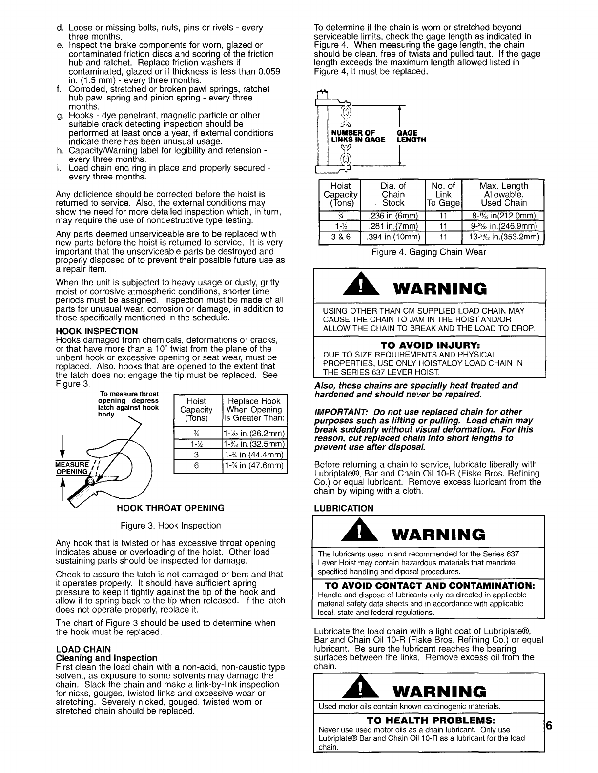
Chain for excessive wear or stretch (see page
6)
every three months.
b.
Worn, cracked or distorted parts such as lower hook
block, upper hook block, upper hook pin, chain guide
roller, stripper, side plates, gear cover, gears,
bushings, lever, brake cover, free chaining knob,
ratchet hub pawl, cam guide, friction hub and lever
ratchet hub -every three months.
c.
Inspect for wear
on
the tip of the pawls, teeth of the
ratchet, and pockets of the liftwheel -every three
months.

d.
Loose or missing bolts, nuts, pins or rivets -every
three months.
e.
Inspect the brake components for worn, glazed or
contaminated friction discs and scoring of the friction
hub and ratchet. Replace friction washers if
contaminated, glazed or if thickness is less than 0.059
in. (1.5 mm) -every three months.
f.
Corroded, stretched or broken pawl springs, ratchet
hub pawl spring and pinion spring -every three
months.
g.
Hooks -dye penetrant, magnetic particle or other
suitable crack detecting inspection should be
performed at least once a year, if external conditions
indicate there has been unusual usage.
h.
Capacity/Warning label for legibility and retension -
every three months.
i.
Load chain end ring in place and properly secured -
every three months.
Any deficience should
be
corrected before the hoist is
returned to service. Also, the external conditions may
show the need for more detailed inspection which,
in
turn,
may require the use of non::!8structive type testing.
Any parts deemed unserviceable are to be replaced with
new parts before the hoist is returned to service. It is very
important that the unserviceable parts be destroyed and
properly disposed of to prevent their possible future use as
a repair item.
When the unit is subjected to heavy usage or dusty, gritty
moist or corrosive atmospheric conditions, shorter time
periods must be assigned. Inspection must be made of all
parts for unusual wear, corrosion or damage, in addition to
those specifically mentioned
in
the schedule.
HOOK INSPECTION
Hooks damaged from chemicals, deformations or cracks,
or that have more than a 100 twist from the plane of the
unbent hook or excessive opening or seat wear, must be
replaced. Also, hooks that are opened to the extent that
the latch does not engage the tip must be replaced. See
Figure
3.
t
To
measure
throat
opening
depress
latch against
hook
body.
Hoist
Capacity
(Tons)
%
1-if
3
6
Figure
3.
Hook Inspection
Replace Hook
When Opening
Is
Greater Than:
HI" in.(26.2mm)
1-%,
in.(32.5mm)
1-%
in.(44.4mm)
Hi
in.(47.6mm)
Any hook that is twisted or has excessive throat opening
indicates abuse or overloading of the hoist. Other load
sustaining parts should be inspected for damage.
Check to assure the latch is not damaged or bent and that
it operates properly. It should have sufficient spring
pressure to keep
it
tightly against the tip of the hook and
allow
it
to spring back to the tip when released.
If
the latch
does not operate properly, replace
it.
The chart of Figure 3 should be used to determine when
the hook must be replaced.
LOAD CHAIN
Cleaning
and
Inspection
First clean the load chain with a non-acid, non-caustic type
solvent, as exposure to some solvents may damage the
chain. Slack the chain and make a link-by-link inspection
for nicks, gouges, twisted links and excessive wear or
stretching. Severely nicked, gouged, twisted worn or
stretched chain should be replaced.
To
determine if the chain is worn or stretched beyond
serviceable limits, check the gage length as indicated in
Figure 4. When measuring the gage length, the chain
should be clean, free of twists and pulled taut. If the gage
length exceeds the maximum length allowed listed in
Figure
4,
it must be replaced.
~~
1
~,.:;:,
NUMBER
OF
GAGE
LINKS IN
GAGE
LENGTH
@------L-l
Hoist Dia. of No. of Max. Length
Capacity Chain Link Allowable.
(Tons) Stock
To
Gage Used Chain
%
.236
in.(6mm)
11
8-
1
)1"
in(212.0mm)
1-/f
.281
in.(7mm)
11
9-'%,
in.(246.9mm)
3&6
.394
in.(10mm)
11
13-'%,
in.(353.2mm)
Figure
4.
Gaging Chain Wear
A
WARNING
USING
OTHER
THAN
CM
SUPPLIED
LOAD
CHAIN
MAY
CAUSE
THE
CHAIN
TO
JAM
IN
THE
HOIST
AND/OR
ALLOW
THE
CHAIN
TO
BREAK
AND
THE
LOAD
TO
DROP.
TO
AVOID
IN.JURY:
DUE
TO
SIZE
REQUIREMENTS
AND
PHYSICAL
PROPERTIES,
USE
ONLY
HOISTALOY
LOAD
CHAIN
IN
THE
SERIES
637
LEVER
HOIST.
Also, these chains are
specially
heat treated
and
hardened
and
should
ne'/er be repaired.
IMPORTANT: Do
not
use replaced chain
for
other
purposes
such
as
lifting
or
pulling.
Load
chain
may
break
suddenly
without
visual deformation.
For
this
reason,
cut
replaced chain
into
short
lengths to
prevent
use
after
disposal.
Before returning a chain to service, lubricate liberally with
Lubriplate®, Bar and Chain Oil 10-R (Fiske Bros. Refining
Co.) or equal lubricant. Remove excess lubricant from the
chain by wiping with a cloth.
LUBRICATION
A
WARNING
The
lubricants
used
in
and
recommended
for
the
Series
637
Lever
Hoist
may
contain
hazardous
materials
that
mandate
specified
handling
and
diposal
procedures.
TO AVOID CONTACT AND CONTAMINATION:
Handle
and
dispose
of
lubricants
only
as
directed
in
applicable
material
safety
data
sheets
and
in
accordance
with
applicable
local,
state
and
federal
regulations.
Lubricate the load chain with a light coat of Lubriplate®,
Bar and Chain Oil 10-R (Fiske Bros. Refining Co.) or equal
lubricant. Be sure the lubricant reaches the bearing
surfaces between the links. Remove excess oil from the
chain. A
WARNING
Used
motor
oils
contain
known
carcinogenic
materials.
TO
HEALTH
PROBLEMS:
Never
use
used
motor
oils
as
a
chain
lubricant.
Only
use
Lubriplate®
Bar
and
Chain
Oil
1
O-R
as
a
lubricant
for
the
load
chain.
6

7
The Hoist normally requires no additional lubrication except
when it has been disassembled for cleaning or repairs.
The brake is designed
to
operate dry. Do
not
use
any
grease
or
lubricant
on the braking surfaces. When
lubricating parts adjacent
to
the brake,
do
not
use an
excessive amount
of
lubricant
which
could
seep
onto
the brake surfaces.
A
WARNING
Using any grease or lubricant on the braking surfaces will cause
hrake slipage and loss of load control which may result
in
injury
and/or property damage.
TO AVOID INJURY:
Do
not use any grease or lubricant on braking surfaces. The brake
is designed to operate
dry.
When the hoist
is
disassembled for cleaning or repairs, the
following locations should be lubricated with approximately
one
oz.
per hoist of Molykote BR-2-S (Dow Corning),
Molytex #2 (Texaco) or Topmoly (Topsail) grease or equal
lubricant: gears, bearing balls of upper and lower hooks,
upper hook pin, rollers of the liftwheel bearing (1-1/2 thru 6
ton units), inside of chain guide roller, exterior of pinion
shaft, surface of ratchet hub pawl, surfaces of frame
bushings, surface of cam guide and gear cover bushings.
Be sure to thoroughly clean the old grease from these parts
before re-Iubricating.
To assure extra
long
life
and
top
performance, be sure
to lubricate the various
parts
of
the
hoist
using
the
lubricants
specified
above.
If
deSired, these
lubricants
can be
purchased
from
eM.
DISASSEMBLY AND
ASSEMBLY INSTRUCTIONS
The exploded views and parts list
on
pages 9 and 10 show
the general arrangement and nomenclature of the parts of
the Series 637 Lever Hoist. These should be used when
disassembling and re-assembling the units so that all parts
are properly installed.
Disassembly
Four points of caution to be observed upon disassembly of
the tool are:
1.
Loose rollers are used for the liftwheel bearing
on
the 1-
1/2, 3 and 6 ton units (refer to parts list for number
required). Care must be taken so
as
to not lose or
misplace these rollers since they may drop from the unit
as the various parts are disassembled.
2.
The latch
is
secured to the hook (upper and lower) by a
rivet.
To
remove the latch, it is necessary to remove the
head of the rivet by grinding or drilling. For replacement
of the latch, refer to paragraph 4 under assembly
instructions.
3.
On
the 3/4, 1-1/2 and 3 ton units, the upper and lower
hook blocks contain loose ball bearings and care must
be taken
so
as
to not lose or misplace these upon
disassembly. The number of ball bearings
in
the
u~per
and lower hook blocks are
as
follows:
Capacity
Tons
3/4
1-1/2
3
No.
of Bearings
Balls
9
13
15
These bearing balls are retained
in
the upper and lower
hook blocks by a set screw that
is
located under the
retainer spring.
To
expose the set screw, work the spring,
one coil at a time,
on
to or off of the hook body.
Similarly, 17 bearing balls are used to support the lower
hook
on
the 6 ton unit. These are retained
in
the hook
trunnion by a set screw
in
the end of the trunnion shaft.
4.
The pinion shaft and ratchet hub pawl and
shaft are under spring pressure and these may
fly out of the unit upon disassembly.
Assembly:
Consideration must be given
to
the following when
assembling the unit:
1.
Assemble the brake components as shown
in
Figure
5.
The ratchet teeth must face
as
shown and engage the
pawls.
RATCHET----'I
[-
FRICTION
'-
LJ,/
HUB--......J.
V
FRICTION DISC
Figure
5.
Brake Component Assembly
On
the lever, set the directional lever
in
the neutral ("N")
position. Making sure that the friction disc
is
centered
on
the friction hub, thread the friction hub into the lever ratchet
hub
in
the lever assembly and firmly hand tighten.
Assemble the cam guide (with the "ears" projecting away
from the lever) onto the splined portion of the friction hub
so
that the cam guide fits into one of the three recessed
portions of the lever ratchet hub and
so
the clearance at "A"
is
slightly smaller than the clearance at "B". Refer to Figure
6.
A
B-~:...J...h
CLEARANCE
AT
A
MUST BE SLIGHTLY
SMALLER THAN
CLEARANCE
AT
B.
II+-+---CAM
GUIDE
Figure
6.
Cam Guide Installation
The friction
hub
must
be
firmly
tightened
into
the
lever
ratchet
hub
before the cam
guide
is
set.
If
the clearance
at
"A"
is
extremely
small, the
tool
will
be
hard
to operate
in
the
unload
direction.
If
the
clearance
at
"8"
is
extremely
small
the brake
will
slip
and
the
tool
will
not
hold
the
load
in
suspension.
After making sure that the cam guide
is
properly
assembled to the lever ratchet hub, spring back the
pawls and assemble the brakellever assembly onto
the pinion shaft and then release the pawls so that
they engage the teeth of the ratchet. Place the free-
chaining knob over the cam guide and secure using
the brake nut, washer and pin.
2.
For proper operation,
37
(for the 1-1/2 ton unit) or 24
(for the 3 & 6 ton units) rollers must be installed for the
liftwheel bearing. Applying grease, Molykote BR-2-S
(Dow, Corning Corp.), to the rollers will help hold them
in
position during assembly.

3.
To
insure proper loading of upper and lower hooks
on
the 3/4, 1-1/2 and 3 ton tools, the correct number of
bearing balls
(9
on
the 3/4 ton unit,
13
on
the 1-1/2 ton
unit and
15
on
the 3 ton unit) must
be
installed
in
the
upper and lower hook blocks.
On
the 6 ton unit, 17
bearing balls must
be
installed
in
the lower hook
trunnion. Apply grease (Molykote BR-2-S, Dow
Corning Corp.) to the bearing balls and feed them into
the small hole
in
the hook block (3/4,1-1/2 and 3 ton
units) or
in
the end of the trunnion shaft
(6
ton
unit).
To
retain the bearing balls and to allow the hook to
rotate freely, thread the set screw into the hole and
tighten firmly. Then, back off the set screw 1 to 1-1/2
turns.
On
the 3/4, 1-1/2 and 3
ton
units,
be
sure to
replace the retainer spring
in
the recess provided for
same
in
the hook block.
4.
When assembling the latch to hook, the end of the
rivet must
be
peened over. When peening over the
rivet, only apply enough force to form a head to retain
the pin. Excessive force will deform the latch and
make the latch inoperablo.
5.
Gearing: When assembling the gears, they must
be
orientated with the timing marks aligned
as
shown
in
Figure
7.
~
TON
Reeving
Tli
...
ING
MARKS
Figure
7.
Gear Timing Marks
3/4,1-112 And 3 Ton Units
l1h. 3 & 6
TON
To
install a new length of load chain,
it
is
necessary to
disengage the old chain from the lower hook block.
To
do
this, work the retainer spring, one coil at a time,
on
to or
off of the hook body. Remove the chain pin to allow the
hook block to
be
removed from the chain. Arrange the
tool for free chaining (see page
4)
and pull the old chain
through the unit. Disengage the free chaining feature and
then set the directional lever to neutral (N). Start
an
upstanding link of the replacement load chain into the
hook side of the tool and between the chain guide roller
and the liftwheel with the weld side of the upstanding links
facing away from the liftwheel. Refer to Figure
8.
CHAIN
GUIDE
ROLLER·LOWER
HOOK
SIDE
STRIPPER-,.."..,---=-
......
LOWER
HOOK
BLOCK-
Figure
8.
Reeving-3/4, 1-1/2 and 3
Ton
Continue to feed the chain
in
to the hoist while turning the
free chaining knob clockwise.
Be
sure to guide the chain
between the liftwheel and chain guide roller
on
the end
ring side of the tool as shown
in
Figure
8.
Continue to
rotate the free chaining knob and pull
on
the loose end of
the chain until a convenient length of chain has been
passed through the unit. Assemble the end ring to the
free end of the chain
by
rotating the last link 1/4 turn and
passing the ends of the ring through the link as shown
in
Figure
8.
Hammer the ends of the ring together to secure
it to the chain. Insert the last link of chain
on
the hook
block side of the tool into the recess
on
top of the hook
block.
To
secure the chain, slide the chain pin through
the hook block and the last link of chain. Slide the
retainer spring up the hook block until it snaps into the
recess for same, to secure the chain pin.
6
Ton
Unit
To
install a new length
of
load chain, it
is
necessary to
disengage the old chain from the upper hook hanger by
removing the dead end bolt, nut and cotter
pin.
Then pull
the old chain through the lower hook block. Arrange the
tool for free chaining (see page
4)
and pull the old chain
through the unit. Disengage the free chaining feature and
then set the directional lever to neutral
(N).
Make sure
that the
new,
replacement chain has
an
odd number of
links. Start
an
upstanding link of the replacement load
chain into the hook side of the unit and between the chain
guide roller and liftwheel, with the weld side of the
upstanding links facing away from the liftwheel. Refer to
Figure
9.
CHAIN GUIDE
ROLLER-END _ 0
RING SIDE
STRIPPER
END
RING
Figure
9.
Reeving - 6
Ton
Feed the chain into the hoist while rotating the free
chaining knob clockwise.
Be
sure to guide the chain
between the liftwheel and the chain guide roller
on
the end
ring side of the tool as shown
in
Figure
9.
Continue to
rotate the free chaining knob and pull
on
the loose end of
the chain until a convenient length of chain has passed
through the unit. Assemble the end ring to the loose end
of the chain
by
rotating the last link 1/4 turn and passing
the ends of the ring through the link as shown
in
Figure
9.
Hammer the ends of the ring together to secure it to the
chain. Place the hoist
in
a vertical position by supporting it
from the upper hook. Remove any twists from the chain
and feed it through the lower hook block and around the
lower sheave. Making sure there are
no
twists
in
the
chain, attach the last link of the chain to the hanger using
the dead end bolt, nut and cotter pin.
8

9
A
WARNING
Failure to properly install the load chain between chain guide rollers
and liftwheel may cause the chain to lift out of the liftwheel pockets
and allow the load to drop.
TO
AVOID
INJURY:
Feed load chain between liftwheel and chain guide, as shown
in
Figures 8 &
9.
RECOMMENDED SPARE PARTS
To
insure continued operation, it
is
recommended that two
friction washers (Key
No.
637-12) for each
eM
Series 637
Lever Hoist
in
service, be kept
on
hand at all times to
replace friction washers that are worn, contaminated or
glazed. See Page 10 for ordering information.
PREVENTATIVE MAINTENANCE
In
addition to the inspection procedures, a preventative
maintenance program should be established to prolong the
useful life of the hoist and maintain its dependability and
continued safe use. The program should include the
periodic inspections with particular attention being paid to
the lubrication of various components using the
recommended lubricants.
TESTING
Prior to initial use, all altered or repaired hoists or used
hoists that have not been operated for the previous 12
months shall be tested by the user for proper operation.
Test the unit first
in
the unloaded state and then with a light
load of 100 pounds(45Kg.) times the number of load
supporting parts of load chain to be sure it operates
properly and the brake holds the load when the lever is
released; then test with a load of 125% of rated capacity.
In
aduition, hoists
in
which load sustaining parts have been
replaced must
be
tested with 125% of rated capacity by or
under the direction of a designated person and a written
report prepared for record purposes.
NOTE: For
additional
information
on
inspection
and
testing
refer
to
ASME B30.21
"Manually
Lever Operated
Hoists"
obtainable
from
ASME
Order
Department, 22
Law Drive,
Box
2300, Fairfield, NJ 07007-2300, U.S.A.
3/4,
1.1/2,
3
and
6 Ton
Series
637
Lever
Hoist
Parts
List
Key
No.
Part
Number
No.
Req'd
Part
Name
3/4
Ton
1-1/2
Ton
3
Ton
6
Ton
Side
Plate
Assembly
(Gear
Side).
637-1
1
Includes
3
Bushings,
4
Studs.
37760C
37733C 37794C 37794C
Liftwheel
and
Liftwheel
Gear.
Side
Plate
Assembly
(Brake
Side).
Includes
637-2
1
Bushing
and
Pawl
Studs
on
3/4
Ton Unit.
37761C
37734C
37795C
37795C
Includes
Bearing
Race
and
2
Pawl
Assemblies
on
1-1/2,
3
and
6 Ton
Units.
637-3
2
Pawl
with
Sprinq
and
Retainer
Rinq
37762C
- - -
637-4
1
Stripper
37763C 37735C
37796C
37796C
637-5
1
Gear
Set
(Includes
2
Gears)
37764C 37736C
37797C
37797C
637-6
1
Sprinq
with
Seat
37765C 37737C
37798C
37798C
637-7
1
Pinion
Shaft
37711C
37738C 37799C
37799C
637-8
1
Gear
Cover
37712C
37739C 37800C
37800C
637-9
1
Gear
Cover
Hardware
Set.
Includes
4
Nuts
and
4
Lockwashers.
37713C 37740C
37801C
37801C
637-10
2
Chain
Guide
Roller
37714C 37741C
37802C
37802C
637-11 1 Friction
Hub
37715C 37742C
37803C
37803C
637-12
2 Friction
Disc
37716C
37743C
22869
22869
637-13
1
Ratchet
37717C 37744C
37805C
37805C
Brake
Cover
for
3/4
Ton
Unit
or
Lever
637-15
1
Ratchet
Hub,
Brake
Cover
and
Lever
Rear
37718C 37745C
37806C
37806C
Half
Assembled
for
1-1/2,
3
and
6 Ton Units.
Brake
Cover
Hardware
Kit,
Includes
637-16
1 4
Nuts
and
4
Lockwashers.
37719C
37746C 37807C 37807C
Lever
Hardware
Kit.
Includes
4
Screws
and
637-17
1 3
Lockwashers
for
the
3/4
Ton Unit.
Includes
37720C 37747C
37747C
37747C
2
Screws.
2
Nuts
and
4
Lockwashers
for
the
1-1/2
3
and
6 Ton
Units.
637-18
1
Lever
Assembly,
Front
Half
includes
Directional
Lever
37721C
37748C
37748C
37748C
637-19
1
Lever
Assembl
Rear
Half
37722C
- -
637-20
1
Cam
Guide
37723C
37749C
37749C
37749C
637-21 1
Free
Chaining
Knob
37724C 37750C
37750C
37750C
637-22
1
Lever
Ratchet
Hub
37725C
-
637-23
1
Brake
Nut,
Washer
and
Cotter
Pin
37726C 37751C 37751C 37751C
637-24
1
Ratchet
Hub
Pawl
Kit.
Includes
Pawl,
37727C
37752C 37752C 37752C
Sprina
and
Shaft.
637-25
1
Lever
Grip
37728C 37753C
37753C
37753C
Upper
Hook
Assembly.
Includes
Hook,
Latch,
Bearing
Balls,
Set
Screw,
Retainer
Spring
and
637-26
1
Hook
Block
for
3/4,1-1/2
and
3 Ton
Units.
37729C
37754C
37815C
37820C
Includes
Hook,
Latch,
Hanger,
Dead
End
Bolt,
Nllt
"no
r.nttAr
Pin
1m
R Tnn
llnit
637-27
1
Upper
Hook
Pin
37730C 37755C
37816C
37816C
Lower
Hook
Assembly.
Includes
Hook,
Latch,
Bearing
Balls,
Set
Screw,
2
Retainer
Springs,
637-28
1
Chain
Pin
and
Hook
Block
for
3/4,1-1/2
37731C 37756C 37817C
37821C
and
3 Ton
Units.
Includes
Hook,
Latch,
Bearing
Balls,
Set
Screw,
4
Retaining
Rings,
Sheave,
Rollers
Sheave
Shaft
and
Hook
Block
for
6 Ton Unit.
637-29
2
Hook
Latch
Kit
37732C
37757C
37818C
37822C
637-30
1
Load
Chain
End
Rinq
40471 40471
37823 37823
637-31 1
Load
Chain,
Specify
Length
Required.
85959
85961
85960 85960
637-32
1
Capacity/Warning
Label
37701C
37702C
37782C
37783C
Bearing
Kit.
Includes
37
Rollers
and
Inner
Ring
637-33
1
for
1-1/2
Ton Unit.
Includes
24
Rollers
and
-
37758C 37819C 37819C
Inner
Ring
for
3
and
6
Ton
Units.

637-27
637-9
637·8
ORDERING INFORMATION: When corresponding or
ordering repair parts always provide:
1)
Hoist Capacity and
2)
Serial Number (Stamped
on
Capacity/Warning Label.) For
parts orders also specify: Key Number of part, part name and
637-26
-,~
number, and quantity desired. When ordering parts consider
,
~
replacing bearings, fasteners, etc. that may
be
damaged or
A 637-5
637-29--
637-27 lost during disassembly or have deteriorated because of age
j!
,
~37-1
-or service. Parts should
be
ordered from CM's
,
!...:
637-7 637-6
~'
~
/637-10
Master Parts Depots.
To
locate the Master Parts
~
~
~
[\
1
i"@
;:;3
~:~(~~~)~~~_~~~4~all
(800) 888-0985 or
~
~
, "
~~
\ 637.13 637-15
~
-'
','2 "
~
I _ 637·11 637·19
f7;:,
-r
(I:,.
,,)
'"
r
fQ
,,,;,;;..
637-17
~
\ \ 637-2
t,
4~'63,:._20.
637·21
637-30
,~~
'~Ij(3~
! 637-23
'Xi
~
637-3 637-12 637-16
""/
~
6 Ton Upper
Hook
637-29
>'637-26
rj
637-29 637-32
~
637-28 637-18
%Ton Lever Hoist
r~'~
A
WARNING
USING "COMMERCIAL" OR OTHER MANUFACTURER'S PARTS
TO
REPAIR THE SERIES 637 LEVER HOIST MAY CAUSE LOAD LOSS.
TO
AVOID
INJURY:
USE ONLY CM SUPPLIED REPLACEMENT PARTS. PARTS MAY
LOOK ALIKE BUT CM PARTS ARE MADE
OF
SPECIFIC MATERIALS
OR PROCESSED TO ACHIEVE SPECIFIC PROPERTIES.
637-28
Exploded Views -Series 637
Manually Operated Lever
Hoists.
~
637-5 ' .
...
~~~
It/!t),
1
~,
3 And 6 Ton Lever Hoists
..
1)0 & 3 Ton Lower Hook
PART
NUMBERS
FOR
PACKAGED
LUBRICANTS
Used
in
the
CM
Series
637
Lever
Hoist
(Refer
to
page
6
for
Lubrication
Instructions)
Lubricant
Type
of
Part
Numbers
and
Packaged
Usage
Lubricant
Quantities
of
Lubricants
Gears,
Rollers
Grease
(Molykote
BR-2-S
28606
-
1/2
Ib.(.23Kg.)
can
of
Liftwheel
and
or
Equal)
28618
- 1
Ib.(.46Kg.)
can
Gear
Bearings
Pawl
Stud
Oil
(WD-40
or
Equal)
Obtain
locally-not
stocked
byCM
Load
Chain
Oil
(Lubriplate
Bar
and
28608
- 1
pint
(.5L)
can
Chain
Oil
10-R
or
Equal)
28619
- 1
gal.(3.8L)
can
637-18
/
I
637-23
637-25
10

© 2000 Columbus McKinnon Corp. Printed in USA
Columbus McKinnon Corporation • Industrial Products Division • 140 John James Audubon Parkway
Amherst, New York 14228-1197 • 1-800-888-0985 • Fax 716-689-5644
®
Note:
When
ordering
parts,
always
furnish
rated
load
and
serial
number
of
hoist
on
which
the
parts
are
to
be
used.
For
the
location
of
the
nearest
eM
Master
Parts
Depot,
call
(800)
888-0985
or
FAX
(71
6)
689-5644.
LIMITATION
OF
WARRANTIES,
REMEDIES
AND
DAMAGES
THE
WARRANTY
STATED
BELOW
IS
GIVEN
IN
PLACE
OF
ALL
OTHER
WARRANTIES,
EXPRESS
OR
IMPLIED,
OF
MERCHANTABILITY,
FITNESS
FOR
A
PARTICULAR
PURPOSE,
OR
OTHERWISE,
NO
PROMISE
OR
AFFIRMATION
OF
FACT
MADE
BY
ANY
AGENT
OR
REPRESENTATIVE
OF
SELLER
SHALL
CONSTITUTE
A
WARRANTY
BY
SELLER
OR
GIVE
RISE
TO
ANY
LIABILITY
OR
OBLIGATION.
Seller
warrants
that
on
the
date
of
delivery
to
carrier
the
goods
are
free
from
defects
in
workmanship
and
materials.
SELLER'S
SOLE
OBLIGATION
IN
THE
EVENT
OF
BREACH
OF
WARRANTY
OR
CONTRACT
OR
FOR
NEGLIGENCE
OR
OTHERWISE
WITH
RESPECT
TO
GOODS
SOLD
SHALL
BE
EXCLUSIVELY
LIMITED
TO
REPAIR
OR
REPLACEMENT,
EO.B.
SELLER'S
POINT
OF
SHIPMENT,
OF
ANY
PARTS
WHICH
SELLER
DETERMINES
TO
HAVE
BEEN
DEFECTIVE
or
if
Seller
determines
that
such
repair
or
replacement
is
not
feasible,
to
a
refund
of
the
purchase
price
upon
return
of
the
goods
to
Seller.
Any
action
against
Seller
for
breach
of
warranty.
negligence
or
otherwise,
must
be
commenced
within
one
year
after
such
cause
of
action
accures.
NO
CLAIM
AGAINST
SELLER
FOR
ANY
DEFECT
IN
THE
GOODS
SHALL
BE
VALID
OR
ENFORCEABLE
UNLESS
BUYER'S
WRITTEN
NOTICE
THEREOF
IS
RECEIVED
BY
SELLER
WITHIN
ONE
YEAR
FROM
THE
DATE
OF
SHIPMENT.
Seller
shall
not
be
liable
for
any
damage,
injury
or
loss
arising
out
of
the
use
of
the
goods
if,
prior
to
such
damage,
injury
or
loss,
such
goods
are
(1)
damaged
or
misused
following
Seller's
delivery
to
carrier;
(2)
not
maintained,
inspected,
or
used
in
compliance
with
applicable
law
and
Seller's
written
instructions
and
recommendations;
or
(3)
installed,
repaired,
altered
or
modified
without
compliance
with
such
law,
instructions
or
recommendations.
UNDER
NO
CIRCUMSTANCES
SHALL
SELLER
BE
LIABLE
FOR
INCIDENTAL
OR
CONSEQUENTIAL
DAMAGES
AS
THOSE
TERMS
ARE
DEFINED
IN
SECTION
2-715
OF
THE
UNIFORM
COMMERCIAL
CODE.
INDEMNIFICATION
AND
SAFE
OPERATION
Buyer
shall
comply
with
and
require
its
employees
to
comply
with
directions
set
forth
in
instructions
and
manuals
furnished
by
Seller
and
shall
use
and
require
its
employees
to
follow
such
instructions
and
manuals
and
to
use
reasonable
care
in
the
use
and
maintenance
of
the
goods.
Buyer
shall
not
remove
or
permit
anyone
to
remove
any
warning
or
instruction
signs
on
the
goods.
In
the
event
of
personal
injury
or
damage
to
property
or
business
arising
from
the
use
of
the
goods,
Buyer
shall
within
48
hours
thereafter
give
Seller
written
notice
of
such
injury
or
damage.
Buyer
shall
cooperate
with
Seller
in
investigating
any
such
injury
or
damage
and
in
the
defense
of
any
claims
arising
therefrom.
If
Buyer
fails
to
comply
with
this
section
or
if
any
injury
or
damage
is
caused,
in
whole
or
in
part,
by
Buyer's
failure
to
comply
with
applicable
federal
or
state
safety
requirements,
Buyer
shall
indemnify
and
hold
Seller
harmless
against
any
claims,
loss
or
expense
for
injury
or
damage
arising
from
the
use
of
the
goods.
A
WARNING
ALTERATIONS OR MODIFICATIONS OF EQUIPMENTAND
USE OF NON·CM REPAIR PARTS CAN LEAD TO
DANGEROUS OPERATION AND INJURY.
TO
AVOID
IN.JURY:
-DO
NOT
ALTER
OR
MODIFY EQUIPMENT
-DO USE ONLY CM PROVIDED REPLACEMENT PARTS.
Table of contents
Other CM Lifting System manuals
Popular Lifting System manuals by other brands

Skyjack
Skyjack SJ 3215 Operation manual

Efco
Efco SwapLoader SL-400 Parts and operation manual

STS
STS STP01-DRU01-EX operating instructions

ShoreStation
ShoreStation Manual SSV50108MS manual

Titan Lifts
Titan Lifts HD2P-10000AC-D Installation, operation & maintenance manual

Pro-Lift
Pro-Lift PL5500 Operating instructions & parts manual