CM Lodestar XL User manual

OPERATING,
MAINTENANCE
& PARTS
MANUAL
ELECTRIC
CHAIN HOIST
Manual No. 652-
Before installing hoist, fill in
the information below. Refer
to the hoist identification
plate.
Model No. __________________
Serial No. __________________
Purchase Date ______________
Voltage ____________________
Rated Capacity______________
52756
XXLL
Rated capacities 2 through 7½ tons/
2000 through 7500 kg
Follow all instructions and warnings for
inspecting, maintaining and operating this hoist.
The use of any hoist presents some risk of personal
injury or property damage. That risk is greatly
increased if proper instructions and warnings are not
followed. Before using this hoist, each operator
should become thoroughly familiar with all warnings,
instructions and recommendations in this manual.
Retain this manual for future reference and use.
Forward this manual to operator.
Failure to operate equipment as directed
in manual may cause injury.
®

CM®XL HOIST PARTS AND SERVICES ARE AVAILABLE IN THE UNITED STATES AND IN CANADA
As a CM® XL Hoist user, you are assured of reliable repair and parts services through a network of Master Parts Depots
and Service Centers that are strategically located in the United States and Canada. These facilities have been selected on
the basis of their demonstrated ability to handle all parts and repair requirements promptly and efficiently.
Below is a list of the Master Parts Depots in the United States and Canada. To quickly obtain the name of the U.S. Service
Center located nearest you, call 314-869-7200 | FAX: 314-869-7226. In the following list, the Canadian Service Centers are
indicated.
i
UNITED STATES MASTER PARTS DEPOT CANADIAN SERVICE CENTERS
MISSOURI
Distributed by Tri-State Equipment Company Inc.
Email: [email protected]
Web: www.tsoverheadcrane.com
PH: 314-869-7200 | FAX: 314-869-7226
COLUMBUS McKINNON, LTD.
10311-174th Street dmonton,
Alberta T5S 1H1

SAFETY PRECAUTIONS
ach CM® Lodestar XL lectric Hoist is built in accordance with the specifications contained herein and at the time of
manufacture complied with our interpretation of applicable sections of the *American Society of Mechanical ngineers
Standard B30.16 “Overhead Hoists,” the National lectrical Code (ANSI/NFPA 70) and the Occupational Safety and
Health Act. Since OHSA states the National lectrical Code applies to all electric hoists, installers are required to pro-
vide current overload protection and grounding on the branch circuit section in keeping with the code. Check each
installation for compliance with the application, operation and maintenance sections of these articles.
The safety laws for elevators, lifting of people and for dumbwaiters specify construction details that are not incorporated in
Lodestar XL hoists. For such applications, refer to the requirements of applicable state and local codes, and the
American National Safety Code for elevators, dumbwaiters, escalators and moving walks (ASM A17.1). Columbus
McKinnon Corporation cannot be responsible for applications other than those for which CM equipment is intended.
* Copies of this Standard can be obtained from ASM Order Department, 22 Law Drive, Box 2300, Fairfield, NJ 07007-2300, U.S.A.
ii
THIS SYMBOL POINTS OUT IMPORTANT SAFETY INSTRUCTIONS WHICH IF NOT FOLLOWED
COULD ENDANGER THE PERSONAL SAFETY AND/OR PROPERTY OF YOURSELF AND OTHERS.
READ AND FOLLOW ALL INSTRUCTIONS IN THIS MANUAL AND ANY PROVIDED WITH THE
EQUIPMENT BEFORE ATTEMPTING TO OPERATE YOUR CM®LODESTAR XL HOIST.
19. Not allow the load chain or hook to be used as an electrical or
welding ground.
20. Not allow the load chain or hook to be touched by a live
welding electrode.
21. Not remove or obscure the warnings on the hoist.
22. Not operate a hoist on which the safety placards or decals are
missing or illegible.
23. Not operate a hoist unless it has been securely attached to a
suitable support.
24. Not operate a hoist unless load slings or other approved single
attachments are properly sized and seated in the hook saddle.
25. Take up slack carefully - make sure load is balanced and load
holding action is secure before continuing.
26. Shut down a hoist that malfunctions or performs unusually and
report such malfunction.
27. Make sure hoist limit switches function properly.
28. Warn personnel of an approaching load.
1. Not operate a damaged, malfunctioning or unusually
performing hoist.
2. Not operate the hoist until you have thoroughly read
and understood this Operating, Maintenance and Parts
Manual.
3. Not operate a hoist which has been modified.
4. Not lift more than the rated load for the hoist.
5. Not use hoist with twisted, kinked, damaged or worn
load chain.
6. Not use the hoist to lift, support, or transport people.
7. Not lift loads over people.
8. Not operate a hoist unless all persons are and
remain clear of the supported load.
9. Not operate unless load is centered under hoist.
10. Not attempt to lengthen the load chain or repair dam-
aged load chain.
11. Protect the hoist’s load chain from weld splatter or
other damaging contaminants.
12. Not operate hoist when it is restricted from forming a
straight line from hook to hook in the direction of loading.
13. Not use load chain as a sling, or wrap load or chain
around load.
14. Not apply the load to the tip of the hook or to the
hook latch.
15. Not apply load unless load chain is properly seated in
the chain wheel(s) or sproket(s).
16. Not apply load if bearing prevents equal loading on all
load chains.
17. Not operate beyond the limits of the load chain travel.
18. Not leave load supported by the hoist unattended
unless specific precautions have been taken.
WARNING
Improper operation of a hoist can create a potentially
hazardous situation which, if not avoided, could
result in death or serious injury. To avoid such a
potentially hazardous situation, the operator shall:
!
!
!
WARNING
Usage of hoists that do not involve lifting of the load
on the lower hook or using hoists in the inverted posi-
tion without special precaution may cause an accident
resulting in injury and/or property damage.
TO AVOID IN URY:
Consult Factory for information concerning using hoists in
these applications.
!
iii
CAUTION
Improper operation of a hoist can create a potentially haz-
ardous situation which, if not avoided, could result in minor
or moderate injury. To avoid such a potentially hazardous
situation, the operator shall:
!
1. Maintain a firm footing or be otherwise secured when operating
the hoist.
2. Check brake function by tensioning the hoist prior to each lift
operation.
3. Use hook latches. Latches are to retain slings, chains, etc. under
slackconditions only.
4. Make sure the hook latches are closed and not supporting any
parts of the load.
5. Make sure the load is free to move and will clear all obstructions.
6. Avoid swinging the load or hook.
7. Make sure hook travel is in the same direction as shown on the
controls.
8. Inspect the hoist regularly, replace damaged or worn parts, and
keep appropriate records of maintenance.
9. Use the hoist manufacturer’s recommended parts when repairing
the unit.
10. Lubricate load chain per instructions in this manual.
11. Not use the hoist load limiting or warning device to measure load.
12. Not use limit switches as routine operating stops unless allowed by
manufacturer. They are emergency devices only.
13. Not allow your attention to be diverted when operating hoist.
14. Not allow the hoist to be subjected to sharp contact with other
hoists, structures, or objects through misuse.
15. Not adjust or repair the hoist unless qualified to perform such
adjustments or repairs.

iii

1
ITEM PAGE NO.
MASTER PARTS DEPOTS AND SERVICE CENTERS. i
SAFETY PRECAUTIONS . . . . . . . . . . . . . ii
HOIST SAFETY IS UP TO YOU. . . . . . . . iii
GENERAL INFORMATION
SPECIFICATIONS . . . . . . . . . . . . . . . . . . . 2
REPAIR/REPLACEMENT POLICY . . . . . . 3
ACCESSORIES . . . . . . . . . . . . . . . . . . . . . . . . 3
INSTALLATION
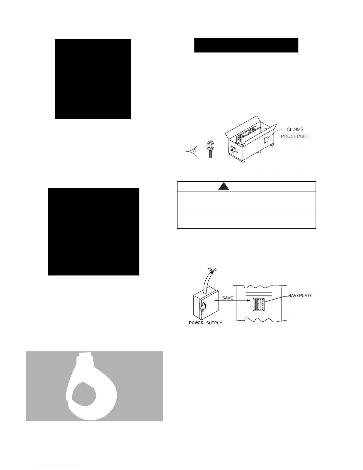
UNPACKING . . . . . . . . . . . . . . . . . . . . . . . . . . . . 4
INSTALLING THE SUSPENSION
HOOK SUSP NSIONS . . . . . . . . . . . . . . . . . . 4
LUG SUSP NSIONS . . . . . . . . . . . . . . . . . . . . . 6
MOUNTING TROLLEY ON HOIST. . . . . . 6
INSTALLING TROLLEY SUSPENDED
HOIST ON BEAM. . . . . . . . . . . . . . . . . . . . .7
INSTALLING BREATHER . . . . . . . . . . . . . . . . 8
POWER SUPPLY SYSTEM . . . . . . . . . . . . . . . 8
ELECTRICAL CONNECTIONS
SINGL SP D DUAL VOLTAG
HOISTS (AND MOTOR DRIV N TROLL YS) . 9
ALL HOISTS. . . . . . . . . . . . . . . . . . . . . . . . . 9
CH CKING FOR TWIST IN LOAD CHAIN . 10
CH CKING FOR AD QUAT VOLTAG . . 10
CHECKING LIMIT SWITCH OPERATION . . . 10
CHAIN CONTAINER. . . . . . . . . . . . . . . . . . . . 10
CONTROL CORD . . . . . . . . . . . . . . . . . . . . . . . 10
OPERATING INSTRUCTIONS
GENERAL . . . . . . . . . . . . . . . . . . . . . . . . . . . . 11
ALL HOISTS . . . . . . . . . . . . . . . . . . . . . . . . . . . . . 11
HOIST WITH PLAIN TROLLEY . . . . . . . . . . . . 11
HOIST WITH GEARED TROLLEY . . . . . . . . . . 11
HOIST WITH MOTOR DRIVEN TROLLEY . . 11
SAFETY PROCEDURES. . . . . . . . . . . . . . . . . . . 11
ITEM PAGE NO.
MAINTENANCE
INSPECTIONS . . . . . . . . . . . . . . . . . . . . . . . . . . 12
FR QU NT INSP CTIONS . . . . . . . . . . . . . . 12
P RIODIC INSP CTIONS . . . . . . . . . . . . . . . 12
HOOK INSP CTION . . . . . . . . . . . . . . . . . . . 12
LOAD CHAIN . . . . . . . . . . . . . . . . . . . . . . . . . 13
PROT CTOR . . . . . . . . . . . . . . . . . . . . . . . . . . 13
LUBRICATION
HOIST . . . . . . . . . . . . . . . . . . . . . . . . . . . . . . . 15
TROLL Y. . . . . . . . . . . . . . . . . . . . . . . . . . . . . 15
AD USTMENTS
HOIST BRAK . . . . . . . . . . . . . . . . . . . . . . . . 15
LIMIT SWITCH S. . . . . . . . . . . . . . . . . . . . 16
TROLL Y BRAK . . . . . . . . . . . . . . . . . . . 17
RECOMMENDED SPARE PARTS . . . . . . . 18
PREVENTIVE MAINTENANCE . . . . . . . . . 18
TROUBLE SHOOTING
ALL HOISTS. . . . . . . . . . . . . . . . . . . . . . . . 19
TWO SP D HOISTS. . . . . . . . . . . . . . . . . 22
MOTOR DRIV N TROLL Y. . . . . . . . . . . . 23
ELECTRICAL DATA . . . . . . . . . . . . . . . . . 24, 25
WIRING DIAGRAMS . . . . . . . . . . . . . . . 26, 28
DISASSEMBLY. . . . . . . . . . . . . . . . . . . . . . . . . 29
REASSEMBLY. . . . . . . . . . . . . . . . . . . . . . . . . . 29
REMOVAL AND REPLACEMENT OF LOAD CHAIN29
REEVING LOAD CHAIN
3,4 AND 5 TON DOUBL R V D UNITS . . 30
5,6 AND 71/2 TON TRIPL R V D UNITS . 31
CUTTING CHAINS. . . . . . . . . . . . . . . . . . . . . . 31
TESTING . . . . . . . . . . . . . . . . . . . . . . . . . . . . . . . 32
REPAIR PARTS
ORDERING INSTRUCTIONS. . . . . . . . . . . . 32
EXPLODED VIEWS AND PARTS LISTS. . 33-48
FOREWORD
This manual contains important information to help you properly install, operate and maintain your hoist for maxi-
mum performance, economy and safety.
Please study its contents thoroughly before putting your hoist into operation. By practicing correct operating proce-
dures and by carrying out the recommended preventative maintenance suggestions, you will experience long, depend-
able and safe service. After you have completely familiarized yourself with the contents of this manual, we recom-
mend that you carefully file it for future reference.
The information herein is directed to the proper use, care and maintenance of the hoist and does not comprise a
handbook on the broad subject of rigging. Rigging can be defined as the process of lifting or moving heavy loads
using hoist and other mechanical equipment. Skill acquired through specialized experience and study is essential to
safe rigging operations. For rigging information, we recommend consulting a standard textbook on the subject.
TABLE OF CONTENTS

SPECIFICATIONS
The CM®LOD STAR XL lectric Chain Hoist is a highly
versatile material handling device that can be used to
lift loads that are within its rated load capacity. Single
and Two speed units with rated loads up to 7½ tons
(7500 kg.) are
available. The hoist can be supplied with a single hook
suspension up to 6 ton (6000 kg.) capacity or suspended
from a plain, geared or motor driven trolley. The stan-
dard lift is 10 feet and longer lifts can be provided on a
per order basis.
The standard features of the CM® LOD STAR XL lectric
Chain Hoist include:
• Hardened, alloy steel, oblique lay liftwheel pro-
vides constant chain speed and reduces chain wear.
• Hoistaloy®load chain for long and dependable
service.
• Lightweight cast aluminum frame and covers.
• Surface hardened, alloy steel, helical gears run-
ning in an oil bath provide smooth and quiet
operation.
• Protector that prevents lifting an excessive overload.
• Single or two speed hoist duty motor equipped
with thermal protection.
• Low voltage control circuit. 115 volt is standard.
24 or 48 volt control circuits are also available.
• Hardened, forged steel hooks equipped with latch.
2
TABLE 1—SPECIFICATIONS
LODESTAR XL ELECTRIC CHAIN HOISTS
TONS 2 3 4 & 5 5 5 6 7½
RATED LOAD Kg. 2000 3000 4000 & 5000 5000 5000 6000 7500
*LIFTING SPEEDS AVAILABLE:
FPM 18 24 30 9 12 15.2 6 8 6 8 10 6 10
SINGLE SPEEDS
MPM 5.5 7.3 9.1 2.7 3.6 4.6 1.8 2.4 1.8 2.4 3.0 1.8 3.0
FPM 6 /18 8 / 24 3/9 4/12 2/6 2.7/8 2/6 2.7/8 2/6
TWO SPEEDS N/A N/A N/A N/A
MPM 1.8 / 5.5 2.4 / 7.3 .9/2.7 1.2 / 3.6 .6 / 1.8 .8 / 2.4 .6/1.8 .8/2.4 .6/1.8
FEET 127 139 71 60 65 106 42 46 42 46 71 42 71
MAXIMUM LIFT
METERS 39 42 22 19 21 32 13 14 13 14 22 13 22
REEVING OF LOAD CHAIN SINGLE DOUBLE TRIPLE
MINIMUM HEADROOM
HOOK SUSPENDED—IN. (mm) 25 (635) 35.31 (897) 36.18 (919) N/A
TROLLEY SUSPENDED—IN. (mm) 28.69 (729) 33 (841) 33.38 (848) 34.25 (870) 34.25 (870)
RANGE OF TROLLEY AD USTABILITY 6 X 12.5 #TO 8 X 18.4#TO 20 X 66.0#
“S” BEAMS 15 X 42.9#
IN. 3.33 TO 5.50 4.00 TO 6.250
FLANGE WIDTH
mm 84.5 TO 139.7 101.6 TO 158.8
STANDARD MOTOR DRIVEN TROLLEY 65 (19.8) OR
TRAVEL SPEED—FPM (MPM) 100 (30.4) 50 (15.2)
**APPROX. NET WEIGHT—LBS. (Kg.)
HOOK SUSPENDED 368 (167) 442 (200) 442 (200) 474 (215)
WITH PLAIN TROLLEY 428 (194) 497 (225) 597 (271) 629 (285)
WITH GEARED TROLLEY 473 (215) 512 (232) 607 (275) 639 (290)
WITH MOTOR DRIVEN TROLLEY 483 (219) 582 (264) 632 (287) 664 (301)
*Lifting speeds are based on 60 Hertz power supply. When operating on 50 Hertz, lifting speeds will be 5/6 of those listed.
**Weights are for single speed hoist with 10 ft. (3 M) lift. For two speed hoists, add 10 pounds (4.5 Kg.).
GENERAL INFORMATION
• Oversize reversing and speed selecting contactors
for long, trouble free service.
• Hoist duty, A.C. motor brake plus regenerative braking.
• Weatherproof, CM 2 or 4 direction control station.
•Shielded, lifetime lubricated ball bearings at all rotating
points. Open bearings are used in gear case.
• Voltage conversion board on single speed, dual voltage units.
• Three stage gear reduction.
• Upper and lower screw type limit switches.
CM®LODESTAR
XL Hoist with
Motor Driven
Trolley

REPAIR/REPLACEMENT POLICY
All Lodestar XL lectric Chain Hoists are thoroughly inspect-
ed and performance tested prior to shipment. If any proper-
ly maintained hoist develops a performance problem due to
a material or workmanship defect, as verified by factory,
repair or replacement of the unit will be made to the origi-
nal purchaser without charge. This repair/replacement poli-
cy applies only to LOD STAR XL Hoists installed, maintained
and operated as outlined in this manual, and specifically
excludes parts subject to normal wear, abuse, improper
installation, improper or inadequate maintenance, hostile
environmental effects and unauthorized
repairs/modifications.
We reserve the right to change materials or design if, in our
opinion, such changes will improve our product. Abuse,
repair by an unauthorized person, or use of non-factory
replacement parts voids the guarantee and could lead to
dangerous operation. For full Terms of Sale, see Sales Order
Acknowledgement. Also, refer to the back cover for
Limitations of Warranties, Remedies and Damages, and
Indemnification and Safe Operation.
ACCESSORIES
HOOK SUSPENSIONS
Hook suspensions are available for suspending 2 through 6
ton hoist from a trolley with a single load bar or for sus-
pending the hoist from a fixed structure.
3
LUG SUSPENSIONS
Lug suspensions are required to suspend the LOD STAR XL
lectric Hoist from plain, geared or motor driven trolleys
described below. When the hoist is to be suspended from a
plain, geared or motor driven trolley, the lug suspension is
attached to the hoist prior to shipment.
LUG SUSPENSION
PLAIN TROLLEYS
These are manual push type trolleys designed for use with
the LOD STAR XL lectric Hoist. The trolley is adjustable to
operate on a range of American Standard ‘S’ beams and
flat flanged beams. The plain trolley is mounted on hoist
prior to shipment.
PLAIN TROLLEY
GEARED TROLLEYS
The geared trolley is similar to the plain trolley except it is
moved by the means of a hand chain. The hand chain
rotates a pinion that drives gears attached to trolley wheels
and moves trolley along the beam. The geared trolley is
mounted on the hoist prior to shipment.
MOTOR DRIVEN TROLLEYS
The motor driven trolley is similar to geared trolley except
the hand chain wheel is replaced with a gear reducer and
an electric motor. The motor is energized by a reversing
contactor mounted inside the hoist and it is controlled by
push buttons located in the pendant control station. A
variety of single and two speed trolley travel speeds are
available and the motor driven trolley is mounted on hoist
prior to shipment.
2 ton 3-6 ton
HOOK SUSPENSION

CHAIN CONTAINER
This accessory is used to hold the slack chain and it is
supplied complete with mounting hardware and
instructions. The chain container is recommended for
those applications where the slack chain will interfere
with the load or drag on the floor as may be the case
with double and triple reeved units. Chain containers
are shipped separately and can be furnished for units
already in use.
LATCHLOK®HOOKS
Latchlok hooks are available to replace the standard
upper or lower latch type hooks (2-6 ton only). The
unique design of the Latchlok hook assures that it will
stay locked until the operator releases it by depressing
the release button. It will not open accidentally—even if the
load chain goes slack. Once opened, it can be shut with
one hand or the weight of the load when it is lifted.
Latchlok hooks can be supplied with the hoist or it can
be provided in kit form for hoists already in service.
LATCHLOK®HOOK
INSTALLATION
UNPACKING
After opening the carton, carefully inspect the hoist,
suspension, trolley and chain container for damage that
may have occurred during shipment. If there is damage,
refer to the packing slip envelope.
Make sure that the power supply to which the hoist is
to be connected is the same as that shown on the iden-
tification plate located on the bottom of the hoist. For
single speed, dual voltage hoists, refer to instructions
on page 8.
INSTALLING SUSPENSION
A. HOOK SUSPENSIONS
For hook suspended 2 through 6 ton units, the suspension is
shipped separately and it must be attached to the hoist
as follows:
1. 2 THROUGH 6 TON. Supplied with the hook suspen-
sion is a counterweight that must be attached to the
motor cover using the two long screws provided.
Remove and discard corresponding motor cover
screws. Place counterweight on motor cover and
secure it using the two longer screws. Tighten these
screws to a seating torque of 16 pound feet (22 NM).
WARNING
Operating a unit with obvious external damage may
cause load to drop and that may result in personal
injury and/or property damage.
TO AVOID IN URY:
Carefully check unit for external damage prior to
installation.
!
MAKING SUR TH
HOIST WILL OP RAT
ON TH POW R SUPPLY
SYST M
INSP CT FOR SHIPPING
DAMAG
MOTOR DRIVEN TROLLEY
4

c. After the hook is in the desired position, slide the
suspension adapter into cavity on top of hoist and
secure it using the suspension adapter screw from
the kit. Tighten screw to a seating torque of 16
pound feet (22 NM).
NOTE: INSTALL BREATHER IN MAIN HOUSING
AFTER HOOK SUSPENSION IS ASSEMBLED TO HOIST.
SEE PAGE 8.
3. 3, 4 and 5 Ton Double Reeved and 5 and 6 Ton
Triple Reeved Units. As shipped from the factory, the
hook is rigid with the plane of the hook parallel to
long axis of hoist. The hook can be changed to swivel
type or the plane of the hook can be changed to per-
pendicular to the long axis of the hoist as follows:
a. If a swivel type hook is required, remove and discard
keeper plate screw and keeper plate. Then using a
hammer, drive the hook nut pin into nut so that
the end of the pin is flush with side of the nut.
b. If it is necessary to position the hook so that the
plane of the hook is perpendicular to long axis of
hoist, first convert to a swivel type hook as
described above but do not discard the keeper
plate and screw. Turn hook 90 degrees and insert
loose pin (packed with the suspension) into a hole
in the hook nut. Loosely reassemble keeper plate
to suspension adapter so that the hook is free to
swivel approximately 45 degrees in either direction.
The hook will be made rigid after suspension is attached
to the hoist.
Attach the “XL” label, from the kit, to counterweight in
the recess provided for same.
2. 2 Ton Single Reeved Units. As shipped from the facto
ry, the hook is rigid with the plane of the hook parallel
to the long axis of the hoist. The hook can be changed
to swivel type or the plane of the hook can be changed
to perpendicular to the long axis of the hoist as follows:
a. If a swivel type hook is required, use a 1/4 inch
(6.4 mm) drift, and working through the hole
in the side of the suspension adapter, drive the
hook nut pin into the nut so that it is flush
with the side of the nut. Discard the loose pin
packed with the suspension.
b. If it is necessary to position the hook so that the
plane of the hook is perpendicular to the long
axis of hoist, first convert to a swivel type hook as
described above. Rotate the hook 90 degrees and
slide the loose pin (packed with the suspension)
through the hole in the side of the suspension
adapter and engage the hole in the hook nut.
5
CHANGING
POSITION OF
HOOK
TO CONV RT
TO SWIV L
TYP HOOK
MOUNTING TH
COUNT RW IGHT
INSTALLING
HOOK
SUSP NSION
2 TON UNIT
TO CONV RT TO
SWIV L TYP
HOOK
DRIFT
COU TERWEIGHT

c. Slide the suspension adapter into cavity on top
of hoist. Install dead end bolt and thread it by
hand to engage the dead end block (3, 4 and 5
ton double reeved units) or idler sheave hanger
(5 and 6 ton units). Then tighten dead end bolt
to a seating torque of 120 pound feet (160NM).
If the hook is to be perpendicular to long axis of hoist
per step b above, rotate the hook to that position and
firmly tighten the keeper plate screw while making sure
the loose pin engages the slot in keeper plate.
NOTE: INSTALL BREATHER IN MAIN HOUSING
AFTER HOOK SUSPENSION IS ASSEMBLED TO
HOIST. SEE PAGE 8.
B. LUG SUSPENSIONS
The following instructions are provided to cover
installing the lug suspension after the hoist has been
reassembled following inspection and/or repair. On
hoists shipped from factory, the lug suspension is
installed prior to mounting the trolley.
1. 2 Ton Single Reeved Units. Slide the suspension
adapter into the cavity on top of hoist and secure it
using the suspension adapter screw. Tighten the
screw to a seating torqueof16 pound feet (22 NM).
INSTALLING LUG SUS-
P NSION—2 TON UNITS
INSTALLING
HOOK
SUSP NSION
3, 4, 5, & 6 TON
CHANGING
POSITION OF
HOOK
2. 3, 4 And 5 Ton Double Reeved And 5, 6 And 7½
Ton Triple Reeved Units. Slide the suspension
adapter into cavity on top of hoist. Install dead end
bolt and thread it by hand to engage the dead end
block (3, 4 and 5 ton double reeved units) or idler
sheave hanger (5, 6 and 7 1/2 ton triple reeved
units). Then tighten the dead end bolt to a seating
torque of 120 pound feet (160 NM).
INSTALLING LUG
SUSP NSION—3, 4,
5, 6 AND 7 1/2 TON
MOUNTING TROLLEY ON HOIST
The following instructions are provided to cover mount-
ing plain, geared and motor driven trolleys after the
hoist has been reassembled following inspection and/or
repair. On units shipped from factory, these trolleys are
mounted on the hoists.
1. Measure actual width of the beam flange on which
the trolley is to operate. To determine proper trolley
side frame spacing to assure that adequate wheel
clearance is provided, the distance between the
beam flange and the inside face of the trackwheel
flange (approximately 1/8 to 3/16 inch on straight
runway beams, 3/16 to 1/4 inch on curved beams for
2 ton units. See Figure 2) and (1/4 inch for straight
runway beams, 3/8 inch on curved beams for 3-7 1/2
ton units. See Figure 1).
2. Use Table 2 to determine proper spacing for 2 ton
units. On 3-7 1/2 ton capacity units, proper spacing is
obtained by varying the number of spacer washers
(furnished with trolley) that are installed on the sus-
pension pins.
WARNING
Using other than factory supplied suspension adapter
screw or dead end bolt to attach suspension adapter
to hoist may cause the screw or bolt to break and
allow the hoist and load to fall.
TO AVOID IN URY:
Use only the factory supplied suspension adapter
screw or dead end bolt and tighten these to the seat-
ing torque specified above.
!
MOUNTING
TROLL Y ON
HOIST
HANDWH L OR TROLL Y
MOTOR G AR D OR MOTOR
DRIV N TROLL Y ONLY
Dead End Bolt
6

3. For 2 ton units, assemble a slotted nut to one
end of each suspension bolt and secure it using a
cotter pin. Spread legs of cotter pin to keep it in
place. Using Table 2 as a reference for washer
spacing, assemble side frames and bolts and
washers together as shown below. Do not install
remaining cotter pins at this time. These are to
be installed after the trolley is mounted on the
beam.
For 3-7½ ton units, temporarily assemble trolley to
hoist using 3 or 4 washers at each end of suspension
pins, between side plates and suspension lug. Tighten
pin nuts for accurate check of spacing. Measure the
distance between the inside faces of the trackwheel
flanges and compare to the dimension required.
Remove trolley side plates and add or remove an
equal number of inside spacer washers as required to
obtain proper distance between wheels. When spac-
ing is correct, install all remaining spacer washers on
the outside ends of each suspension pin and secure
the pins with lockwashers and hex nut (See Note
Below). The nuts should not be completely tightened
until after hoist and trolley are mounted onto beam.
NOTE: It is very important that all spacer
washers that come with the trolley be
used. Install remaining spacer washers
equally on outside ends of each
suspension pin.
4. On geared and motor driven trolleys, make sure
the handwheel or motor is on loose end/chain
container side of the hoist.
INSTALLING TROLLEY SUSPENDED HOIST ON
BEAM
Stops must be positioned to contact the trolley side
frames and not exert impact force on the hoist.
Trolleys are mounted on the hoist prior to shipment and side
frames are positioned for the nominal beam flange specified
on the order. However, due to variations in beam flange
widths, actual beam flange width should be measured to
determine the exact distribution of the spacer washers. See
Mounting Trolley On Hoist Section.
WARNING
Operating the trolley on a beam that has no rail stops
may allow the trolley to fall off the end of the beam.
TO AVOID IN URY:
Install rail stops at each end of the beam on which
the trolley is to operate.
WARNING
If washer spacing recommendations are not followed, trol-
ley may fall from beam.
TO AVOID IN URY:
Measure the actual beam flange on which the trolley
is to operate and use Table 2 to determine the
arrangement of the spacer washers for that flange
width.
NOTE: USE OF OTHER THAN SUPPLIED SPACER WASHERS
MAY CAUSE IMPROPER TRACKWHEEL SPACING.
!
Table 2. Trolley Spacer Washer Arrangement
ABCD
3-3/8 (85.7) 13 0013
3-5/8 (92.0) 11 2211
3-7/8 (98.4) 10 349
4 (101.6) 9449
Standard 4-1/8 (104.7) 8558
Trolleys 4-5/8 (117.4) 5885
5 (127.0) 3 10 10 3
5-1/8 (130.1) 3 10 11 2
5-1/4 (133.3) 2 11 12 1
5-1/2 (139.7) 0 13 13 0
5-5/8 (142.9) 12 1112
6 (152.4) 10 3310
6-1/4 (158.7) 9458
6-3/8 (161.9) 8567
Special 7 (177.8) 4994
Trolleys 7-1/8 (181.0) 3 10 10 3
7-1/4 (184.1) 3 10 11 2
7-3/8 (187.3) 2 11 12 1
7-1/2 (190.5) 1 12 12 1
7-5/8 (193.7) 0 13 13 0
* Minimum Beam
Radius ft.(M) 4’-0”(1.22)
*Dimension applies to minimum S-beam and will
vary with larger S-beams
Flange
Width
in.(mm)
2 Ton
No. of Washers
!
Figure 2.
Figure 1.
QUA TITY OF
OUTSIDE WASHERS
SHOULD BE EQUAL
-BOTH SIDES
QUA TITY OF
I SIDE WASHERS
SHOULD BE EQUAL
-BOTH SIDES
7

8
POWER SUPPLY SYSTEM
To insure proper operation, to avoid damage to
hoist and electrical system and to reduce the risk of
electric shock or fire, the branch circuit supplying
power to the hoist must:
1. Have ample capacity to prevent excess voltage
drop during starting and operation (refer to
“Checking for Adequate Voltage at Hoist”See
Pg. 10). When determining the size of branch
circuit components and conductors, special con-
sideration should be given to the starting cur-
rent-amps (approximately three times that
shown on the hoist identification plate) and the
length of the conductors. As a minimum, the
system should be rated for 20 amps and it
should have #12AWG, or larger, wiring.
2. Be in accordance with the National lectrical
Code (ANSI/NFPA-70) and applicable National,
State and Local Codes.
3. ffectively ground the hoist in accordance with
National lectrical Code and other applicable
codes. Proper grounding provides a path of least
resistance for electric current to reduce the risk
of electric shock. The power cord of the hoist
includes a green wire for grounding the hoist to
the external power supply system. If grounding is
to be through the trolley trackwheels, each sec-
tion of the runway must be grounded to the
building ground system using metal to metal
connections.
4. Include slow blow type fuses or inverse trip time
circuit breakers to permit the hoist to start and
accelerate load.
5. Include a disconnecting means capable of being
locked in the “open” position.
Before installing geared or motor driven trolleys (2 ton
only) on the beam, lubricate the trackwheel gears and
pinion with Texaco Novatex #2 or equivalent heavy cup
grease.
On open end beams, remove rail stops, lift hoist/trolley
into position and slide the hoist/trolley assembly onto
beam flange. Reinstall the rail stops.
On closed end beams, loosen the suspension bolt nuts
on one side of trolley and slide one side frame out far
enough to clear the beam flange. Lift hoist/trolley
assembly up so that trackwheels are riding on beam
flange. Draw side frames together by tightening the sus-
pension bolt nuts snugly.
Be sure to install cotter pins through slotted nuts and
hole in suspension bolts and spread legs of cotter pins to
secure on 2 ton units. For 3-7 1/2 ton units, be sure lock-
washers are positioned properly on the suspension pins
and completely tightened.
On geared trolleys, the bottom of the hand chain loop is
normally located two feet (0.6M) above the floor. If it is
desired to change this, find the unwelded link and open
it by spreading with a chisel or twist one end with a
wrench while holding the other end in a vise or another
wrench. Remove an even number of links (2,4,6, etc.) as
necessary to shorten the chain or add an even number
of links to lengthen the chain (when lengthening the
chain, another open link will be required and this can be
made from a welded link by cutting through weld with
a hacksaw). Make certain that the chain is not twist-
ed–then re-install and close open links.
NOTE: AFTER THE UNIT IS CONNECTED TO THE POWER
SUPPLY SYSTEM (SEE BELOW), SUSPEND A
CAPACITY LOAD FROM THE HOIST AND OPERATE
THE TROLLEY OVER THE ENTIRE LENGTH OF THE
RUNWAY OR MONORAIL SYSTEM TO BE SURE
THAT THE AD USTMENTS AND OPERATION IS
SATISFACTORY. ON SYSTEMS WITH CURVES, THE
EDGES OF THE RAIL AT THE CURVED SECTIONS
SHOULD BE KEPT LIGHTLY LUBRICATED WITH
GREASE.
WARNING
An excessively worn beam flange may fail and allow
the trolley to fall from the beam.
TO AVOID IN URY:
Periodically inspect the beam flange for wear. Replace
beam if flange is worn.
!
INSTALLING BREATHER
After the hook suspension is assembled to the hoist or after
the hoist and trolley are mounted on the beam, remove the
upper plug from the main housing (652-110) and install the
breather (from small envelope attached to the power cord).
Failure to install the breather could damage oil seals and thus
cause oil leaks.
INSTALL
BR ATH R
WARNING
Failure to properly ground the hoist presents the danger of
electric shock.
TO AVOID IN URY:
Permanently ground the hoist as instructed in this manual.
!
TYPICAL POW R
SUPPLY SYST M

NOTE: IN THIS MANUAL, NOMINAL VOLTAGES ARE
USED WHEN REFERRING TO POWER SUPPLY
SYSTEMS. HOWEVER, WITH NO MODIFICA-
TION, THE XL HOIST WILL OPERATE ON A
RANGE OF VOLTAGES AS INDICATED BELOW:
NOMINAL VOLTAGE HERTZ
VOLTAGE RANGE
230 208-240 60
460 440-480 60
220 200-240 50
380 365-395 50
415 400-430 50
575 550-575 60
WARNING
Failure to provide a proper power supply system for
the hoist may cause hoist damage and offers the
potential for a fire.
TO AVOID IN URY:
Provide the hoist with a 20 amp, minimum, overcurrent
protected power supply system per the National
lectrical Code (ANSI/NFPA 70) and applicable local
codes as instructed in this manual.
!
ELECTRICAL CONNECTIONS
SINGLE SPEED, DUAL VOLTAGE HOISTS (AND
MOTOR DRIVEN TROLLEYS)
Unless ordered on a special basis, single speed dual voltage
(230/460-3-60, 220/380-3-50 and 220/415-3-50) hoists are factory
wired to operate on 460-3-60 (or 380-3-50 or 415-3-50).
However, a conversion terminal board is provided to easily and
quickly change from 460 to 230 (or 380 to 220 or 415 to 220)
volt operation. The conversion terminal board is located adjacent
to the reversing contactor at motor end of hoist. If necessary,
change voltage connections before connecting hoist to power
supply system as follows:
1. Remove the motor cover (652-182). On units with
hook suspension, it will be necessary to remove the
counterweight (652-219) before removing motor
cover.
2. Shift all eight wires from row of terminals marked
“460” (or 380 or 415) to row of terminals marked
“230” (or 220).
CONV RSION T RMINAL BOARD
MOV ALL 8 WIR S TO CONV RT FROM 460 TO 230
(380 TO 220, 415 TO 220) VOLT OP RATION
HOIST VOLTAG
CONV RSION
3. Reassemble motor cover (and counterweight if so
equipped) to hoist frame.
4. Mark the tag attached to power cord to indicate
that the hoist has been converted to operate on 230
(or 220) volts and restamp hoist identification plate
accordingly.
If the hoist is suspended from a single speed motor driven trol-
ley, it will also be necessary to change the trolley motor
connections. To do this, remove the cover from the ter-
minal box mounted on the side of the trolley motor and
reconnect the trolley motor wires attached to the terminal
board as shown below:
ALL HOISTS
After making sure that the hoist (and motor driven trol-
ley) are wired to operate on the power supply system,
you are now ready to connect hoist power cord to the
power supply. Since these are three phase units, the
hoist motor can rotate in either direction depending on
how it is connected to the power supply. Therefore,
direction of hook movement must be checked during the
original installation and each time the hoist is moved to
a new location.
Always disconnect the hoist from the power supply system or
de-energize the power supply system and follow proper
Lockout/Tagout procedures when working (connecting
or disconnecting) with the hoist electrical connections.
Serious damage will result if the hook is run to upper or
lower limit of lift with hook moving in a direction oppo-
site to that indicated by the control station. Connect
hoist power cord to the power supply and check hook
movement as follows:
1. Move the manual disconnect switch handle to the
“OFF” position.
2. Connect the WHIT -PURPL , R D AND BLACK wires
of hoist power cord to load side of disconnect switch.
Connect the GR N wire of hoist power cord to
power supply ground.
TROLL Y VOLTAG CONV RSION
(Connections shown are for 208-240 volt operation)
WARNING
FAILUR TO FOLLOW PROP R LOCKOUT/TAGOUT PROC DUR S
MAY PR S NT TH DANG R OF L CTRICAL SHOCK.
TO AVOID IN URY:
DISCONN CT POW R AND LOCKOUT/TAGOUT DISCONN CT-
ING M ANS B FOR R MOVING COV R OR S RVICING THIS
QUIPM NT.
(2 TO O LY)
9

10
3. Move the manual disconnect switch handle to the
“ON” position.
4. Depress the (up) control. If the hook moves in the
up direction, the hoist is ready for operation. If the
hook lowers, move the disconnect switch handle to
the “OFF” position and interchange the BLACK and
R D leads at the disconnect switch. Move the discon-
nect switch handle to the “ON” position and the
hoist is now ready for operation.
NOTE: DO NOT CHANGE INTERNAL WIRING OF
HOIST OR CONTROL STATION TO REVERSE
HOOK DIRECTION. THE HOIST AND CONTROL
STATION WIRING WAS INSPECTED AND TEST-
ED FOR PROPER OPERATION AT THE FACTORY.
CHANGING THIS WIRING WILL CAUSE IMPROP-
ER OPERATION AND SERIOUS DAMAGE.
Also, do not force the Protector to compensate for improperly
adjusted limit switches or reverse voltage phasing.
CHECKING FOR TWIST IN LOAD CHAIN
3, 4 And 5 Ton Double Reeved Units
The best way to check for this condition is to run the
lower hook, without a load, up to within about 2 feet
(0.6M) of hoist. If the dead end of chain has been proper-
ly installed, a twist can occur only if the lower hook block
has been capsized between the strands of chain. Reverse
capsize to remove twist.
5,6 And 7 1/2 Ton Triple Reeved Units
On these models, the load chain is dead ended on top of
the lower hook block. If chain has been properly installed,
the only way a twist can occur is if the lower hook block
has been capsized between the strands of chain. If this
has occurred, two strands of chain will be wrapped
around each other and to remove twist, reverse the cap-
size.
CHECKING FOR ADEQUATE VOLTAGE AT HOIST
The hoist must be supplied with adequate electrical
power for proper operation and to reduce problems that
may result from insufficient power (low voltage). These
include:
• Noisy hoist operation due to brake and/or contactor
chatter.
• Heating of the hoist motor and other internal
components as well as heating of wires and con-
nectors in the circuit feeding the hoist.
• Failure of the hoist to lift the load due to motor
stalling.
• Blowing fuses or tripping circuit breakers.
For proper operation and to avoid these low voltage
problems, voltage (measured at the end of the 2.5 foot
(.9 M) power cord while lifting rated load) should be as
follows:
WARNING
Allowing the hook block to run into the bottom of
the hoist when raising a load or allowing the chain to
become taut between the loose end screw and the
frame when lowering a load may break the chain and
allow the load to drop.
TO AVOID IN URY:
Do not allow the hook block to contact the bottom of
the hoist or the loose end chain to become taut.
!
NOMINAL MINIMUM * MIN. VOLTAG
POW R OP RATING AT INSTANT
SUPPLY VOLTAG OF START
208-3-60 187 172
220-3-50 198 182
230-3-60 207 190
380-3-50 365 336
415-3-50 399 367
460-3-60 414 380
* The drop in voltage upon energizing the hoist should
not be below the value listed.
Remember, operation with low voltage can void the
Repair/Replacement policy. When in doubt about any of
the electrical requirements for the power supply system,
consult a qualified electrician.
CHECKING LIMIT SWITCH OPERATION
1. Press the (Up) control and raise the lower hook
until the top of the hook block is about one foot
(0.3M) below hoist.
2. Cautiously continue raising the hook until upper
limit switch stops upward motion. At this point, the
top of the hook block should be 3 inches (76 mm)
below bottom of the hoist.
3. If adjustment is necessary, see page 16.
4. Press (Down) control and cautiously lower hook until
lower limit switch stops the downward motion. From
10 to 12 chain links should be between the loose end
link and the opening for the chain in bottom of hoist.
If adjustment is necessary, see page 16.
CHAIN CONTAINER
If a chain container is to be used, attach it to the hoist
frame and place chain in container per instructions provid-
ed with the chain container kit. After the chain container
is installed, follow the instructions on page 16 to reset
upper limit switch so uppermost point of hook travel is
just below the bottom of the chain container.
UNDER NO CIRCUMSTANCES SHOULD THE HOOK
BLOCK OR LOAD BE PERMITTED TO COME IN CON-
TACT WITH THE CHAIN CONTAINER. IF CONTACT IS
MADE, THE FUNCTION OF THE CHAIN CONTAINER CAN
BE INTERFERED WITH, THE CONTAINER MAY BE DAM-
AGED AND IT COULD FALL OFF OF THE HOIST.
CONTROL CORD
Unless ordered on a special basis, the hoist is supplied
with a control cord that will position the control station
approximately 4 feet (1.2M) above the lower hook when
it is at the lower limit of lift. If this places the control sta-
tion too close to the floor, a “control cord alteration kit”
(Key No. 627-474, Part Number 28642) can be obtained
from factory for shortening the length of the control
cord.
WARNING
Allowing the hook block to run into the bottom of
hoist when raising a load or allowing the chain to
become taut between the loose end screw and the
frame when lowering a load may break the chain and
allow the load to drop.
TO AVOID IN URY:
Do not allow the hook block to contact the bottom of
hoist or the loose end chain to become taut.
!

11
WARNING
Tying knots or loops to shorten the drop of the control sta-
tion will make the strain relief ineffective and the
internal conductors of the cord may break.
TO AVOID IN URY:
Shorten the control cord using the control cord alter-
ation kit and the instructions provided with the kit.
!
OPERATING INSTRUCTIONS
GENERAL
1. The Protector is designed to allow the first reduction gear
to slip on an excessive overload. An overload is indicated
when the hoist will not raise the load. Also, some clutching
noise may be heard if the hoist is loaded beyond rated
capacity. Should this occur, immediately release the (Up)
control to stop operation of the hoist. At this point, the
load should be reduced to the rated hoist capacity or the
hoist should be replaced with one of the proper capacity.
When the excessive load is removed, normal hoist opera-
tion is automatically restored.
CAUTION: THE PROTECTOR IS SUSCEPTIBLE TO OVER
HEATING AND WEAR WHEN SLIPPED FOR
EXTENDED PERIODS. UNDER NO CIRCUM-
STANCE SHOULD THE PROTECTOR BE
ALLOWED TO SLIP FOR MORE THAN A FEW
SECONDS.
Due to the above, a hoist equipped with a Protector is not
recommended for use in any application where there is a
possibility of adding to an already suspended load to the
point of overload. This includes *dumbwaiter installations,
containers that are loaded in mid-air, etc.
*Refer to limitations on Page ii concerning dumb-
waiter applications.
Also, if a XL Hoist with a Protector is used at unusual
xtremes of ambient temperatures, above 150°F (65°C) or
below 15° F (-9°C) changes in lubricant properties may
permit the hoist to raise larger loads than under normal
operating conditions and presents possibility of damage
or injury.
2. All hoists are equipped with an adjustable screw
limit switch, which automatically stops the hook at
any predetermined point when either hoisting or lowering.
3. The control station used on two speed hoists is similar to
single speed unit, except that either of two definite
speeds may be selected by the operator in both
hoisting and lowering. ach control when partially
depressed provides SLOW speed and when fully
depressed gives FAST speed. Partial release of con-
trol returns hoist to slow speed, while complete
release allows hoist to stop. Rated lifting speeds are
shown on hoist identification plate. SLOW speed is
intended as a means of carefully controlling or
“spotting” the load, although the hoist may be
operated solely at this speed if desired. It is not nec-
essary to operate in the SLOW speed position as the
hoist will pick up a capacity load at FAST speed
from a standing start. In other words, it is not nec-
essary to hesitate at the slow position when moving
control from STOP and FAST position or vice versa.
4. If material being handled must be immersed in
water, pickling baths, any liquid, dusty or loose
solids, use a sling chain of ample length so that the
hook is always above the surface. Bearings in the
hook block are shielded only against ordinary atmos-
pheric conditions.
5. Read operation section of American National
Standard ASM B30.16.
ALL HOISTS
1. Before picking up a load, check to see that the hoist
is directly overhead.
2. WH N APPLYING A LOAD, IT SHOULD B DIR CTLY
UND R HOIST OR TROLL Y. AVOID OFF-C NT R
LOADING OF ANY KIND.
3. Take up a slack load chain carefully and start load
easily to avoid shock and jerking of hoist load
chain. If there is any evidence of overloading,
immediately lower the load and remove the excess
load.
4. Do not allow the load to swing or twist while hoisting.
5. Do not allow the load to bear against the hook latch.
HOIST WITH PLAIN TROLLEY
This unit should be moved by pushing on the suspended load
or by pulling the empty hook. However, the unit can also be
moved by pulling on the control station since an internal steel
cable extends the length of the control cord and is anchored to
the hoist and to the control station.
HOIST WITH GEARED TROLLEY
This unit should be moved by means of the pendant
hand chain. Pull on the chain farthest from end toward
which the unit is to travel.
HOIST WITH MOTOR DRIVEN TROLLEY
This unit should be moved by operating the controls
marked < FORWARD and > R V RS in control station.
Anticipate the stopping point and allow trolley to coast
to a smooth stop. Reversing or “plugging” to stop trolley
causes overheating of motor and swaying of load.
SAFETY PROCEDURES
For safety precautions and a list of Do’s and Do Not’s for
safe operation of hoists, refer to page ii.
1. When preparing to lift a load, be sure that attach-
ments to hook are firmly seated in hook saddle.
Avoid off center loading of any kind, especially
loading on the point of hook.
2. When lifting, raise load only enough to clear the
floor or support and check to be sure that the
attachments to the hook and load are firmly seated.
Continue lift only after you are assured the load is
free of all obstructions.
3. Do not load hoist beyond the rated load shown on
hoist identification plate and capacity labels.
Overload can cause immediate failure of some load-
carrying part or create a defect causing subsequent
failure at less than rated load. When in doubt, use
the next larger capacity of XL Hoist.

12
GENERAL
1. The Protector is designed to allow the first reduction gear
to slip on an excessive overload. An overload is indicated
when the hoist will not raise the load. Also, some clutching
noise may be heard if the hoist is loaded beyond rated
capacity. Should this occur, immediately release the (Up)
control to stop operation of the hoist. At this point, the
load should be reduced to the rated hoist capacity or the
hoist should be replaced with one of the proper capacity.
When the excessive load is removed, normal hoist opera-
tion is automatically restored.
CAUTION: THE PROTECTOR IS SUSCEPTIBLE TO OVER
HEATING AND WEAR WHEN SLIPPED FOR
EXTENDED PERIODS. UNDER NO CIRCUM-
STANCE SHOULD THE PROTECTOR BE
ALLOWED TO SLIP FOR MORE THAN A FEW
SECONDS.
Due to the above, a hoist equipped with a Protector is not
recommended for use in any application where there is a
possibility of adding to an already suspended load to the
point of overload. This includes *dumbwaiter installations,
containers that are loaded in mid-air, etc.
*Refer to limitations on Page ii concerning dumb-
waiter applications.
Also, if a XL Hoist with a Protector is used at unusual
xtremes of ambient temperatures, above 150°F (65°C) or
below 15° F (-9°C) changes in lubricant properties may
permit the hoist to raise larger loads than under normal
operating conditions and presents possibility of damage
or injury.
2. All hoists are equipped with an adjustable screw
limit switch, which automatically stops the hook at
any predetermined point when either hoisting or lowering.
3. The control station used on two speed hoists is similar to
single speed unit, except that either of two definite
speeds may be selected by the operator in both
hoisting and lowering. ach control when partially
depressed provides SLOW speed and when fully
depressed gives FAST speed. Partial release of con-
trol returns hoist to slow speed, while complete
release allows hoist to stop. Rated lifting speeds are
shown on hoist identification plate. SLOW speed is
intended as a means of carefully controlling or
“spotting” the load, although the hoist may be
operated solely at this speed if desired. It is not nec-
essary to operate in the SLOW speed position as the
hoist will pick up a capacity load at FAST speed
from a standing start. In other words, it is not nec-
essary to hesitate at the slow position when moving
control from STOP and FAST position or vice versa.
4. Do not use this or any other overhead materials han-
dling equipment for lifting persons.
5. Stand clear of all loads and avoid moving a load over
the heads of other personnel. Warn personnel of
your intention to move a load in their area.
6. Do not leave load suspended in air unattended.
7. Permit only qualified personnel to operate unit.
8. Do not wrap the load chain around the load and
hook onto itself as a choker chain.
Doing this will result in:
a. The loss of the swivel effect of the hook which
could mean twisted chain and a jammed lift
wheel.
b. The upper limit switch is by-passed and the load
could hit the hoist.
c. The chain could be damaged at the hook.
9. On double and triple reeved hoists, check for twists
in the load chain. A twist can occur if the lower
hook block has been capsized between the strands
of chain. Reverse the capsize to remove the twist.
10. Do not allow the load to bear against the hook
latch. The latch is to help maintain the hook in posi-
tion while the chain is slack before taking up slack chain.
11. Take up a slack load chain carefully and start load eas
ily to avoid shock and jerking of hoist load chain. If
there is any evidence of overloading, immediately
lower the load and remove the excess load.
12. Do not allow the load to swing or twist while hoisting.
13. Never operate the hoist when flammable materials or
vapors are present. lectrical devices produce arcs or
sparks that can cause a fire or explosion.
14. STAY AL RT! Watch what you are doing and use
common sense. Do not use the hoist when you are
tired, distracted or under the influence of drugs,
alcohol or medication causing diminished control.
INSPECTION
To maintain continuous and satisfactory operation, a
regular inspection procedure must be initiated to
replace worn or damaged parts before they become
unsafe. Inspection intervals must be determined by the
individual application and are based on the type of ser-
vice to which the hoist will be subjected and degree of
exposure to wear, deterioration or malfunction of the
critical components.
WARNING
Allowing the load to bear against the hook latch
and/or hook tip can result in loss of load.
TO AVOID IN URY:
Do not allow the load to bear against the hook latch
and/or hook tip. Apply load to hook bowl or saddle
!
MAINTENANCE
The type of service to which the hoist is subjected can be
classified as “Normal,” “Heavy,” or “Severe.”
Normal Service: Involves operation with randomly distrib-
uted loads within rated load limit, or uniform loads less
than 65 percent of rated load for not more than 25 per-
cent of the time.
Heavy Service: Involves operating the hoist within rated
load limit which exceeds normal service.
Severe Service: Normal or heavy service with abnormal
operating conditions.
Two classes of inspection—Frequent and Periodic—
must be performed.
FREQUENT INSPECTIONS: These inspections are visu-
al examinations by the operator or other designated per-
sonnel. Records of such inspections are not required. The
frequent inspections are to be performed monthly for
normal service, weekly to monthly for heavy service, and
daily to weekly for severe service, and they should
include those items listed in Table 3.
PERIODIC INSPECTIONS: These inspections are visual
inspections of external conditions by an appointed per-
son. Records of periodic inspections are to be kept for
continuing evaluation of the condition of the hoist.
Periodic inspections are to be performed yearly for nor-
mal service, semi-annually for heavy service and quarterly
for severe service, and they are to include those items
listed in Table 4.
CAUTION: ANY DEFICIENCIES ARE TO BE CORRECTED
BEFORE THE HOIST IS RETURNED TO SER-
VICE. ALSO, THE EXTERNAL CONDITIONS
MAY SHOW THE NEED FOR DISASSEMBLY
TO PERMIT A MORE DETAILED INSPECTION,
WHICH, IN TURN, MAY REQUIRE THE USE
OF NONDESTRUCTIVE TYPE TESTING.
HOOK INSPECTION
Hooks damaged from chemicals, deformations or cracks,
or that have more than a 10° twist from the hook’s
unbent plane, excessive opening or seat wear must be
replaced. Also, hooks that are opened and allow the
latch to not engage the tip must be replaced. Any hook
that is twisted or has excessive throat opening indicates
abuse or overloading of the unit. Inspect other load sus-
taining parts for damage.
On latch type hooks, check to make sure that the latch is
not damaged or bent and that it operates properly with
sufficient spring pressure to keep the latch tightly
against the tip of the hook and allow latch to spring
back to tip when released. If latch does not operate
properly, it should be replaced. See below to determine
when the hook must be replaced.

13
Replace Hook
When Opening
Is Greater
Than
1 1/2 IN.
38.1 mm
2 3/8 IN.
60.3 mm
CAPACITY
(TONS)
2
3,4,5,6 AND 7 ½
LATCH TYP HOOK
(Upper and Lower)
TO M ASUR OP NING,
D PR SS LATCH AGAINST
HOOK BODY AS SHOWN.
*UPP R HOOK NOT AVAIL ABL
FOR 7 1/2 TON
Replace Hook
When Opening
Or Seat are:
CAPACITY
(TONS)
2
3,4,5, and 6
LATCHLOCK® TYP HOOK
(UPP R AND LOW R)
“A” Max.
2 1/2 IN.
63.5 mm
2 15/16 IN.
74.6 mm
“B” Mn.
1 1/8 IN.
28.5mm
113/32 IN.
35.7mm
Hook Inspection
M ASUR
OP NING
“A”
“B” Max.
LOAD CHAIN
Cleaning and Inspection
First clean load chain with a non-acid or non-caustic type
solvent. Then slack the chain and make a link-by-link
inspection for nicks, gouges, twisted links and excessive
wear or stretching. Chain exhibiting wear should be
checked throughout its entire length and replaced if
worn beyond serviceable limits.
Checking For Load Chain Wear
Slack the portion of the chain that normally passes over
the liftwheel. xamine the interlink area for the point of
maximum wear (polishing). Measure and record the stock
diameter at this point of the link. Then measure stock
diameter in the same area on a link that does not pass
over the liftwheel (use the link adjacent to the loose end
link for this purpose). Compare these two measurements.
If the stock diameter of the worn link is 0.010 inches
(0.254mm), or greater, less than the stock diameter of
the unworn link, the chain must be replaced.
Note that worn chain can be an indication of worn hoist
components. For this reason, the hoist’s chain guides,
hook blocks and liftwheel should be examined for wear
and replaced as necessary when replacing worn chain.
Also, these chains are specially heat treated and hard-
ened and should never be repaired.
WARNING
Using other than factory supplied load chain may
cause the chain to jam in the hoist and/or allow the
chain to break and the load to drop.
TO AVOID IN URY:
Due to size requirements and physical properties, use
only Hoistaloy®load chain in the XL Hoists.
!
IMPORTANT:
DO NOT USE REPLACED CHAIN FOR OTHER PURPOS-
ES SUCH AS LIFTING OR PULLING. LOAD CHAIN MAY
BREAK SUDDENLY WITHOUT VISUAL DEFORMATION.
FOR THIS REASON, CUT REPLACED CHAIN INTO
SHORT LENGTHS TO PREVENT USE AFTER DISPOSAL.
PROTECTOR™
The Protector should operate for the normal life of hoist
without service. The device has been calibrated at the
factory for a specific capacity/gear ratio of XL Hoist. It is
not adjustable and it is not interchangeable with other
capacities/gear ratios.
XL Hoist with
Motor Driven
Trolley

14
Table 3. Minimum Frequent Inspections
TYP OF S RVIC IT M
Normal Heavy Severe
a) Brake for evidence of slippage.
b) Control functions for proper operation.
c) Hooks for damage, cracks, twists, excessive throat opening. latch engagement
and latch operation–see page 13.
d) Load chain for adequate lubrication, as well as for signs of wear, damaged links
or foreign matter–see page 15.
e) Load chain for proper reeving and twists.
Daily
to Weekly
Weekly
to Monthly
Monthly
Table 4. Minimum Periodic Inspections
IT M
Normal Heavy Severe
TYP OF S RVIC
a) All items listed in Table 3 for frequent inspections.
b) xternal evidence of loose screws, bolts or nuts.
c) xternal evidence of worn, corroded, cracked or distorted hook block, gears,
bearings, dead end block, dead end pin, dead end bolt and suspension components.
d) xternal evidence of damage to hook retaining nut and pin. Also check the
upper suspension adapter making sure it is fully seated in the hoist frame and
that suspension adapter screw or dead end bolt is tight.
e) xternal evidence of damage or excessive wear of the liftwheel and hook block
sheave chain pockets. Widening and deepening of the pockets may cause the
chain to lift-up in the pocket and result in binding between liftwheel and chain
guide or between the sheave and hook block. Also, check the chain guide for
wear or burring where the chain enters the hoist. Severely worn or damaged
parts should be replaced.
f) xternal evidence of excessive wear of brake parts, and brake adjustment—see
page 15.
g) xternal evidence of pitting or any deterioration of contactor contacts. Check
the operation of the control station making sure the buttons operate freely and
do not stick in either position.
h) Inspect the electrical cords and cables and control station enclosure for damaged
insulation.
i) Inspect trolley trackwheels for external wear on tread and flange and for wear
on internal bearing surfaces as evidenced by a looseness on the stud.
Suspension components for damage, cracks, wear and operation. Also check sus-
pension adapter screw or dead end bolt for proper tightness—(see pages 4,
5,and 6).
j) Inspect the loose end link, loose end screw, dead end block on double reeved
units and dead end plate on triple reeved units. Replace worn or distorted parts.
k) Inspect the hook for excess free play or rotation. Replace worn parts as evidenced
by excess free play or rotation.
l) Inspect for oil leaks at the gasket on either side of intermediate plate. Tighten
the screws used to attach the main housing and brake housing to intermediate
plate. If leak persists, disassemble hoist (see page 27) and replace gaskets.
m) Inspect inside of motor and brake housings for presence of oil. Oil in motor
housing may be excess chain lubricant or a leaking seal. Wipe out oil and moni-
tor. If leak persists, replace seal (652-122 or 652-132). Oil in brake housing is due
to leaking seal. Replace seal (652-122 or 652-134).
n) Check motor bolts for damage and replace if bent, cracked or damaged.
o) Inspect all splines for signs of wear and deterioration. Replace splined parts if
worn or damaged.
Yearly
very 6 Months
very 3 Months

15
LUBRICATION
NOTE: TO ASSURE EXTRA LONG LIFE AND TOP PERFOR-
MANCE, BE SURE TO LUBRICATE THE VARIOUS
PARTS OF THE XL HOIST USING THE LUBRICANTS
SPECIFIED BELOW. IF DESIRED, THESE LUBRCANTS
MAY BE PURCHASED FROM THE FACTORY.
HOIST LUBRICATION
Gears. Check oil level in gear housing at least once a
month, maintaining it at the bottom of oil level hole in
main housing (652-110).
Drain housing every 2-3 years and refill with one gallon
(3.86 liters) of gear oil Amoco 85W-140.
CAUTION: THE PROTECTOR IS TO OPERATE IN THE
ABOVE MENTIONED OIL. DO NOT USE ANY
OTHER TYPE OF LUBRICANT OR THE
PROTECTOR WILL NOT OPERATE PROPERLY
AND PARTS COULD BE DAMAGED.
The limit switch gears are of molded nylon and require no
lubrication. Apply a light film of machine oil to the limit
switch shaft threads at least once a year.
Chain Guides, Liftwheel & Sheave Wheels.
When the hoist is disassembled for inspection and/or
repair, the chain guides, sheave wheels (on multi-reeved
units) and liftwheel must be lubricated with Lubriplate Bar
and Chain Oil 10-R (Fiske Bros. Refining Co.) prior to
reassembly. Apply sufficient lubricant to obtain natural
runoff and full coverage.
Load Chain. Keep chain lubricated with a small amount
of lubricant. This will greatly increase the life of load
chain. Do not allow the chain to run dry.
Keep it clean and lubricate at regular intervals with
Lubriplate Bar and Chain Oil 10-R (Fiske Bros. Refining
Co.) or equal lubricant. Normally, weekly lubrication and
cleaning is satisfactory, but under hot and dirty conditions,
it may be necessary to clean the chain at least once a day
and lubricate it several times between cleanings. When
lubricating the chain, apply sufficient lubricant to obtain
natural runoff and full coverage.
WARNING
The lubricants used in and recommended for the XL Hoist
may contain hazardous materials that mandate specific han-
dling and disposal procedures.
TO AVOID CONTACT AND CONTAMINATION:
Handle and dispose of lubricants only as directed in applicable
material safety data sheets and in accordance with applicable
local, state and federal regulations.
!
WARNING
Used motor oils contain known carcinogenic materials.
TO AVOID HEALTH PROBLEMS:
Never use used motor oils as a chain lubricant. Only
use Lubriplate Bar and Chain Oil 10-R as a lubricant
for the load chain.
!
Bearings. All bearings except the lower hook thrust
bearings are pre-lubricated or are in an oil bath and
need no lubrication. The lower hook thrust bearing
should be lubricated at least once a month with heavy
duty machine oil.
Miscellaneous. If unit is disassembled, splines inside
coupling (652-103) should be coated with an P type
grease (such as vans Products Co. Anti-Scoring xtreme
Pressure Lub. No. 3) before reassembly.
TROLLEY LUBRICATION
Trackwheel bearings are pre-lubricated and require no lubrication.
Geared Trolley. Once a month lubricate trackwheel
gears with Texaco Novatex No. 2 or an equivalent heavy
cup grease or graphite grease.
very six months lubricate handwheel shaft bearings in
3-in-1 machine oil.
Motor Driven Trolley. Once a month lubricate track-
wheel gears with Texaco Novatex No. 2 or an equivalent
heavy cup grease or graphite grease.
For 2 ton trolleys, the motor bearings and reduction gears
require no additional lubrication. However, if gears are disas-
sembled, upon reassembly use Texaco Novatex No. 1 or an
equivalent medium cup grease.
For 3-7 1/2 ton trolleys, the right angle worm gear reducer oil
should be changed after the first 100 hours of operation, then
after every 2500 hours of normal service. When replacing oil
due to repairs or service, use Mobil SHC-626 or equal, for
each oil change.
AD USTMENTS
HOIST BRAKE
The correct air gap between armature and field when brake is
not energized, is 0.025 inch (.63 mm) and need not be adjusted
until the gap reaches 0.045 inch (1.14 mm).
To adjust the brake, proceed as follows:
1. Disconnect hoist from power supply.
2. Remove brake end cover.
3. Before adjusting the gap, back off the brake nuts
and examine friction linings and friction surfaces for
wear, scoring or warpage (min.thk. .188). Also check
shading coils to be sure they are in place and not
broken. A missing or broken shading coil will cause
the brake to be noisy when hoist is operated. Any of
these symptoms indicate the need for replacement of
parts.
4. Turn brake nuts clockwise gaging the air gap on
each side and at both ends of the armature.
5. Replace cover, reconnect the power and check operation.
HOIST BRAK
ADJUSTM NT

16
LIMIT SWITCHES
If limit switch operation has been checked as described
on page 10 and is not operating correctly or is not auto-
matically stopping the hook at a desired position, pro-
ceed as follows:
1. Disconnect hoist from power supply.
2. Remove brake end cover.
3. The positions of upper and lower limit switches are
indicated on the fiber insulator.
4. Loosen the screws to permit guide plate to be moved
out of engagement with the traveling nuts.
5. Reconnect hoist to power supply
6. Run hook to the desired upper or lower position,
cautiously operating the hoist without load.
7. Disconnect hoist from power supply.
8. Moving one travel nut toward the other increases
hook travel and away from the other decreases the
travel. To adjust the upper limit, turn the nut nearest
the switch indicated as “Upper Limit Switch”. To adjust
the lower limit, turn the nut nearest the switch marked
“Lower Limit Switch”. Turn the desired nut until it
just breaks the limit switch contacts. An audible click
will he heard as the switch opens. Continue to
rotate the nut toward the switch an additional two
full teeth.
9. Reposition the guide plate in the next slot and
securely tighten screws.
10. Reconnect hoist to power supply and check the stop-
ping point of the hook by first moving the hook
about 10 inches (254 mm) away from the desired
stopping point. Then move the hook towards the
desired stopping point by jogging cautiously until
the limit switch stops the motion. If the stopping
point is not the desired position, repeat the above
instructions.
11. Double check the adjustment by moving the hook
about 2 feet (610 mm) from the desired stopping
point and then run the hook into the limit with the
control held in the fully depressed position.
12. Fine adjustment of the screw limits setting may be
obtained by inverting the guide plate. The offset on
the plate gives adjustments equivalent to 1/2 notch
(see Table below). When inverting the plate, it may
be necessary to use the notch adjacent to the one
used in the preliminary setting.
1
4
3
2
5
LIMIT SWITCHES
1. Limit switch sub-assy 4 Guide Plate
2. Limit switch shaft 5. Screws
3. Traveling nuts
HOOK TRAVEL PER NOTCH OF
LIMIT SWITCH NUT
* At 60 Hertz. For 50 Hertz speeds are 5/6 of those listed.
Fast speeds are listed for two speed units.
RAT D
LOAD
TONS
(Kg.)
*LIFT
SP D
FPM
(MPM)
MAX.
LIFT
FT. (M)
HOOK
TRAV L
P R
NOTCH
IN.(mm)
2 (2000) 18 (5.5) 127 (39) 1.10 (27.9)
2 (2000) 1 24 (7.3) 139 (42) 1.27 (32.3)
2 (2000) 30 (9.1) 212 (65) 0.63 (16.0)
3 (3000) 9 (2.7) 60 (18) 0.55 (14.0)
3 (3000) 12 (3.6) 65 (20) 0.64 (16.1)
3 (3000) 15.2 (4.6) 106 (32) 0.93 (23.6)
4 (4000) 9 (2.7) 60 (18) 0.55 (14.0)
4 (4000) 2 12 (3.6) 65 (20) 0.64 (16.1)
4 (4000) 15.2 (4.6) 106 (32) 0.93 (23.6)
5 (5000) 9 (2.7) 60 (18) 0.55 (14.0)
5 (5000) 12 (3.6) 65 (20) 0.64 (16.1)
5 (5000) 15.2 (4.6) 106 (32) 0.93 (23.6)
5 (5000) 6(1.8) 42 (13) 0.37 (9.3)
5 (5000) 8(2.4) 46 (14) 0.42 (10.8)
6 (6000) 6 (1.8) 42 (13) 0.37 (9.3)
6 (6000) 3 8 (2.4) 46 (14) 0.42 (10.8)
6 (6000) 10 (3.0) 71 (22) 0.63 (16.0)
7½ (7500) 6 (1.8) 42 (13) 0.37 (9.3)
7½ (7500) 10 (3.0) 71 (22) 0.63 (16.0)
PARTS
OF
CHAIN
(R VING)
Other manuals for Lodestar XL
1
Table of contents
Other CM Lifting System manuals
Popular Lifting System manuals by other brands

Lockhard
Lockhard Alulift Series Operator's manual

Pentalift
Pentalift ULTRAHOOK UHR40 owner's manual

Challenger Lifts
Challenger Lifts 44030 Installation, operation & maintenance manual

Prism Medical UK
Prism Medical UK C1000 owner's manual

WALTCO
WALTCO 79255TL owner's manual

Global Lift
Global Lift Superior Series owner's manual

WERTHER INTERNATIONAL
WERTHER INTERNATIONAL MONOLIFT 800 Instruction and maintenance manual

WPG
WPG MRTALPCH611LDC3 operating instructions

Manitou
Manitou 80 VJR Operator's manual

AMGO Hydraulics
AMGO Hydraulics OH-12 Installation and service manual

Larzep
Larzep HN-480 instruction manual

Anchor
Anchor APEX 80 Use and maintenance