3
A. SAFETY INSTRUCTIONS & PRECAUTIONS
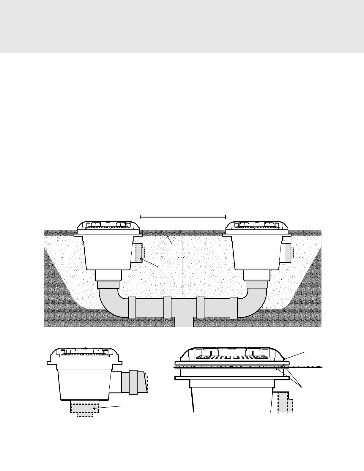
When using two or more suction ttings on a common suction line, suctions must be separated by a minimum of 3
ft or they must be located on two dierent planes.
WARNING: DO NOT locate suction outlets on seating areas or on backrests for such seating areas.
Attention Installer: This manual contains important information about the installation, operation and safe use of this
product. Before installing this product, read and follow all warning notices and instructions which are included. This
information should be given to the owner and/or operator of this equipment.
To reduce the risk of drowning from hair and body entrapment, install suction ttings with a marked ow rate in
gallons per minute that exceeds the ow rate of your system by at least 25%. Always use multiple suction outlets. If
the tting/cover breaks, is damaged, or is missing, shut the system down immediately. Do not use the system until
damaged parts have been replaced.
Keep hair and clothing a minimum of 12 inches from all suction ttings and drains at all times. Persons with long
hair should secure hair to a minimal length or wear swimming cap. Children should never be left unattended at any
time in a swimming pool, spa, or bathtub. Be sure the temperature of the water never exceeds the manufacturer’s
recommendations.
To reduce the risk of injury, installation and service should be done by a qualied Service Professional, certied
electrician or authorized CMP representative.
NOTE: In the event that one suction outlet is completely blocked, the remaining suction outlet(s) serving that system
MUST have a ow rating capable of the full ow of the pump(s) for the specic suction system.
Increasing size of the pump may increase ow rate of suction beyond rated safety limits causing entrapment or
death.
All Suction Outlet Fitting Assemblies (SOFAs) shall be installed in accordance with the manufacturer’s installation
instructions, or for Registered Design Professional SOFAs, in accordance with the registered design professional’s
engineering plans. Field modication made to a SOFA not authorized by the manufacturer’s installation instructions
shall void the SOFA certication.
Hair or body parts blocking the spa or pool suctions may become trapped and held against the suction tting.
Entrapment against the suction ttings can result in drowning or other severe injury. Never sit on or lean up against
suction ttings. Never exceed the maximum allowable ow rate stated on the suction tting. The suction tting and
fasteners should be inspected for damage or tampering before use. Missing, broken, or cracked suction ttings shall
be replaced. Loose suction ttings shall be reattached or replaced before use of this facility.
The maximum hose length dierence between any self-contained SOFA and the tee leading to the pump shall not
exceed 13 feet (3.96 m).
CMP drain covers are only certied for use with CMP sumps and frames. Do not mismatch with parts from other
manufacturers.
When installing and using this equipment, basic safety precautions shall always be followed, including the following:
IMPORTANT SAFETY INSTRUCTIONS.
READ, UNDERSTAND AND FOLLOW ALL INSTRUCTIONS.
ALWAYS PLUMB AND INSTALL ALL SUCTION FITTINGS ACCORDING TO ALL
BUILDING CODES THAT APPLY IN YOUR AREA.
WARNING
WARNING
WARNING
WARNING
WARNING
NOTICE
NOTICE
NOTICE
NOTICE
NOTICE
NOTICE
NOTICE
SAVE THESE INSTRUCTIONS