CMT ORANGE TOOLS CMT650 User manual

CMT650
Worktop Jig
Sistema de junta para encimeras de cocina
Système de jonction pour les plans de cuisine
Sistema di giunzione per piani da cucina
Verbindungssystem für Küchenarbeitsflächen
Instruction Manual
Manual de instrucciones
Manuel d’utilisation
Manuale di istruzioni
Gebrauchsanweisungen
EN p. 2
ES p. 16
FR p. 30
IT p. 44
DE S.58
Index of Contents
2www.cmtutensili.com
SAFETY!!!
The symbols shown on the cover of this manual advise that you wear
the correct safety protection when using this machine.
Safety Protection Symbols
Index of Contents 2
What’s in the Box 3
What else you will need 4
General Safety Instructions 5-6
CMT worktop jig configuration 7
General guidelines for cutting Worktop joints 8
Cutting 90 degree worktop joints 9-10-11
Cutting out of square joints 12
Cutting 45-degree worktop joints 13
Cutting the worktop joint clamp recesses 13
Assembling worktop joints 14
Other applications for the CMT650 worktop jig 14-15
S
a
f
e
t
y
h
e
l
m
e
t
D
u
s
t
m
a
s
k
E
a
r
d
e
f
e
n
c
e
r
s
S
a
f
e
t
y
h
e
l
m
e
t
P
r
o
t
e
c
t
i
v
e
g
l
o
v
e
s
S
a
f
e
t
y
s
h
o
e
s
What’s in the box...
3
www.cmtutensili.com
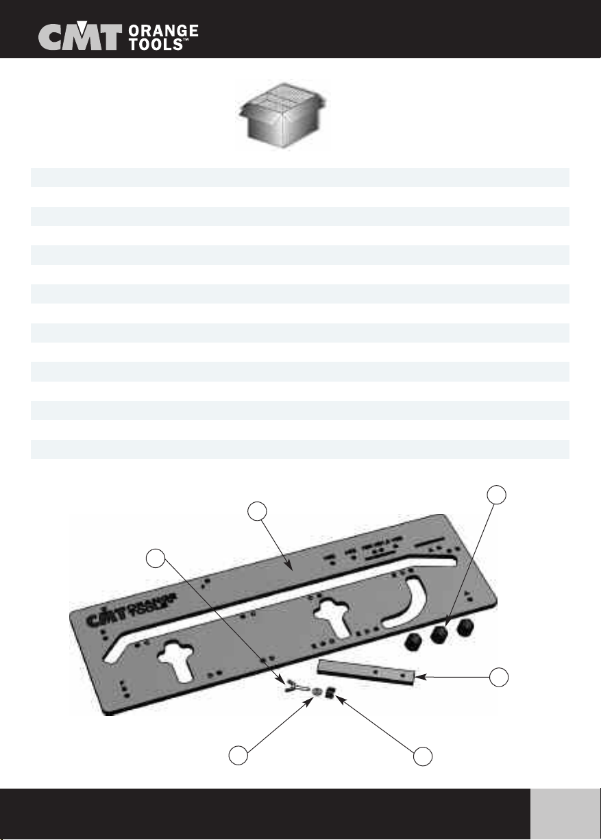
Model Number: CMT650 Worktop Jig
A
B
D
FE
C
Nr. 1 A CMT650 Phenolic plastic worktop jig
Nr. 3 B Positioning pegs fitted with rubber O-rings (2 rings per peg)
Nr. 1 C Phenolic length stop finger
Nr. 1 D M8 knob
Nr. 1 E M8 countersunk bolt
Nr.1 F M8 washer
Nr. 1 Instruction Manual

What else you will need...
4www.cmtutensili.com
AHeavy duty router with 12mm or 12.7mm (1/2") collet
B30mm guide bush (code 899.007.00)
CCollet spanner and guide bush fixing screws
DPair of clamps (ideally long reach with soft facings or pads
to protect face of worktop)
EØ12mm x 50mm (40mm for thinner worktops) router cutter
(either 2 flute cutter or replaceable tip cutter).
FEar protectors and safety goggles or visor
B
A
F
D
E
C

General safety instructions...
5
www.cmtutensili.com
Good Working Practices/Safety
The following suggestions will enable you to observe good working prac-
tices, keep yourself and fellow workers safe and maintain your tools and
equipment in good working order.
Safety Guide Lines
1. Ensure that you are conversant with using the router before attempting to use this Jig.
2. Always follow the router manufacturers guidelines and safety procedures.
3. If you have not used a worktop jig previously, make a series of trial cuts in scrap pieces of worktop
to gain experience of the procedure, sequence and cutting characteristics of both the material, rou-
ter and jig.
4. Always wear protective goggles and earmuffs when routing.
5. Always wear a dust mask or respirator and use dust extraction equipment whenever possible.
6. Avoid wearing loose clothing and keep long hair tied back.
7. Always remove spanners/keys from the router and do not leave them loose on the work surface or
jig while routing.
8. Always switch off and wait until the router cutter has stopped rotating before lifting the router from
face of the work.
9. Always clamp the worktop to a secure rigid surface while cutting.
10. Whenever possible always cut the worktop joints before cutting the tops to length.
WARNING!!!
Keep tools and equipment out of the reach of young children.
General safety instructions...
6www.cmtutensili.com
Cutters and Collets
When cutting worktops the abrasive nature of the chipboard core and
laminate faces rapidly wears the cutting edges of any cutter including
tungsten carbide tipped cutters. Any cutter is unlikely to cut more than
three complete worktop joints perfectly cleanly (i.e. male and female
parts). Ensure that cutters are cleaned and sharpened (hand sharpened
on a diamond stone) between cutting each complete joint.
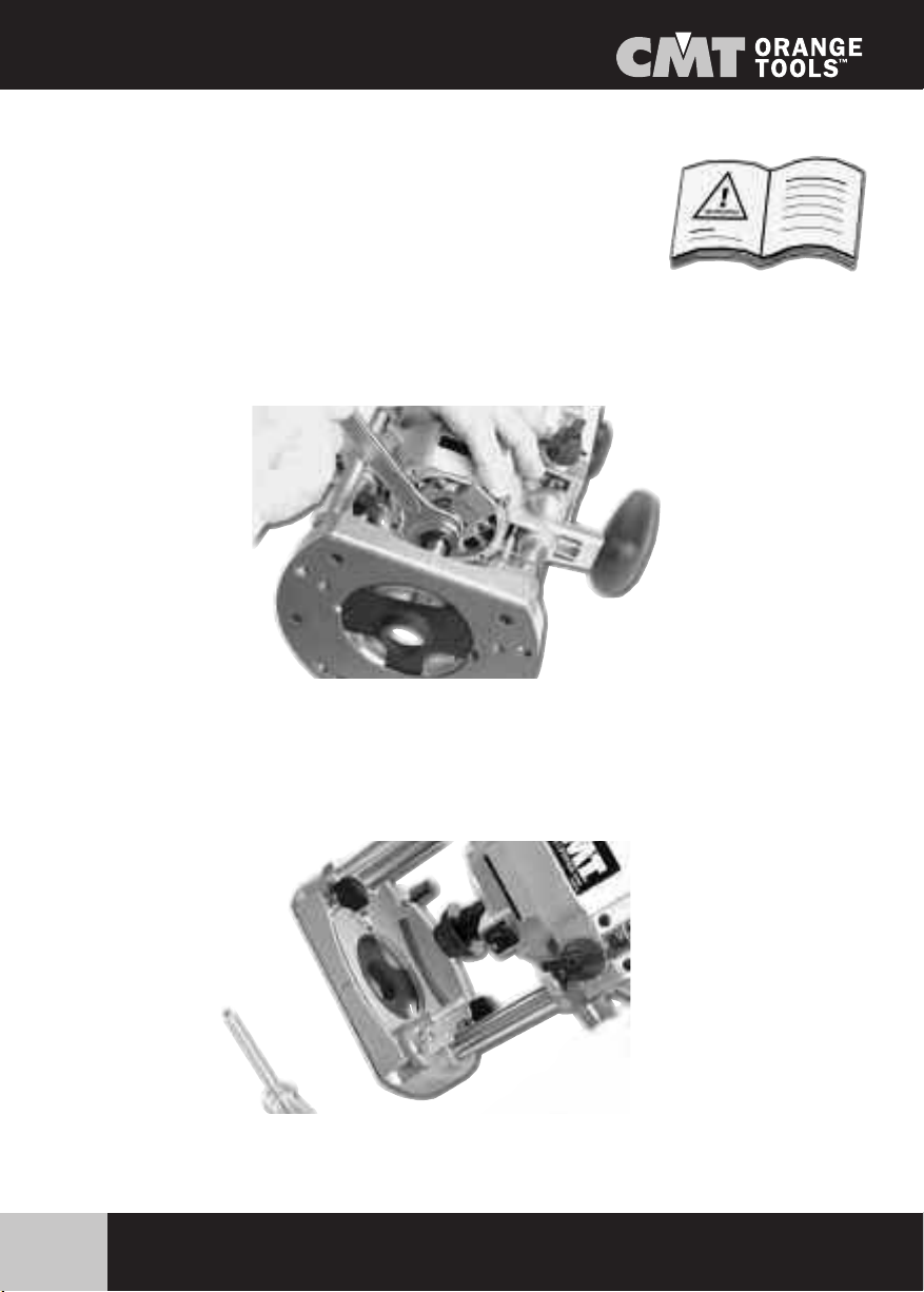
Ensure that the cutter is correctly held in the router collet
(see router manufacturers instruction manual)
Always check that the guide bush is fitted concentric to
the cutter, preferably using a centering mandrel.
CMT worktop jig configuration...
7
www.cmtutensili.com
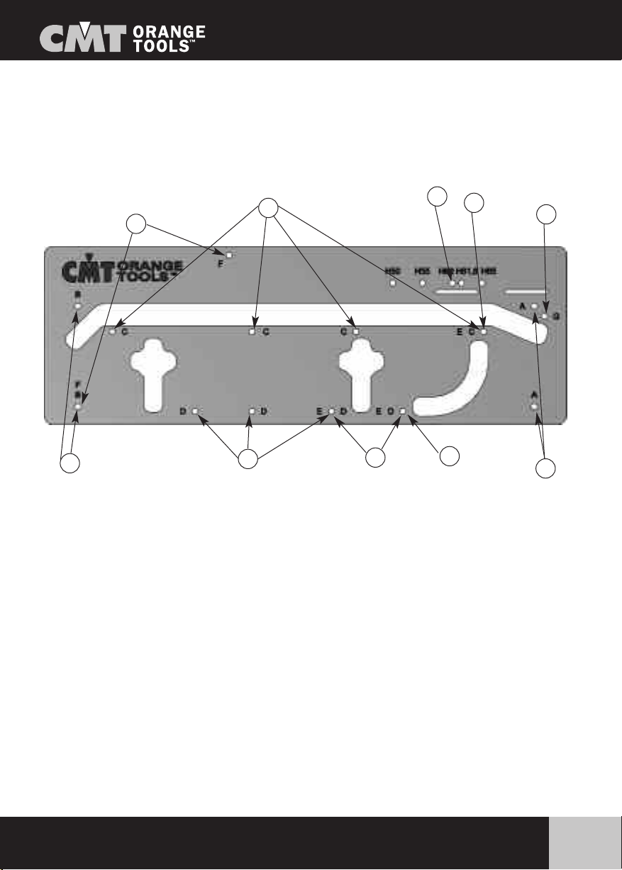
For precise positioning on the worktop, the CMT worktop jig is fitted with three steel stops fitted into
specific holes in the jig to suit each specific operation.
Each stop is fitted with two neoprene o-rings to hold it securely into the hole. If the stop is difficult to
fit, apply a drop of oil or soap to the o-rings.
Ensure that the stops are pushed fully into the holes flush to the underside of the jig.
The holes for the steel stops are indicated by letters for each specific operation
A. 2 holes - outer part of 45° joint
B.2holes - outer partof 90° joint
C.4holes - inner partof 90° and 45° joints
D. 4 holes - fixing holes for clamps
E.3holes - radius finishing of corners (r8,2)
F. 2 holes - 45° finishing of corners
G. 1 hole - inner part of 45° joint
H. 1 hole - inner part of 90° joint (worktop 500, 550, 600, 616, 650mm only)
NOTE: The CMT jig must be used with a 30mm guide bush and a 12mm cutter fitted to
the router. This allows for a cutter offset from the edge of the jig of 9 mm.
F
C
BDED
G
A
HE
General guidelines for cutting worktop joints...
8www.cmtutensili.com
Always ensure that you are cutting from the correct face and into the postform (rounded) edge of the
worktop.When cutting, the direction of rotation of the cutter (i.e. clockwise) will cut cleanly into the left
hand side of the cut, but will tear the face off of the right hand side. Therefore the waste portion of the
worktop must always be on the right hand side.
When cutting worktops to length etc, use a jigsaw to cut away much of the waste to within 3mm of the
required cut line and then trim the cut edgewith the router guided against the edgeof the jig. This will
leave a straight square edge to align the jig stops against.
Remember always cut into the post-formedge, never out of it.
Always fit soft packing under the clamp heads when clamping against the laminate face of the worktop.
When possible always leave the worktop over-length to allow the joint to be re-cut if incorrectly cut the
first time.

Cutting 90 degree worktop joints...
9
www.cmtutensili.com
When cutting a 90-degree joint to the right hand end of the worktop, have the
worktop (decorative laminate) face up. For the matching male joint turn the worktop face down.
When cutting a 90-degree joint to the left hand end of the worktop, have the worktop (decorati-
ve laminate) face down. For the matching male end joint turn the worktop face up.
The first step is to set the jig to suit the width of the worktop. If it is a standard 600mm worktop, then
stop position Hcan be used. If there is any discrepancy in the exact width or if the worktop is wider or
narrower than this then the sliding width stop must be used.
PLEASE NOTE!!!
Cutting 90 degree worktop joints continued...
10 www.cmtutensili.com
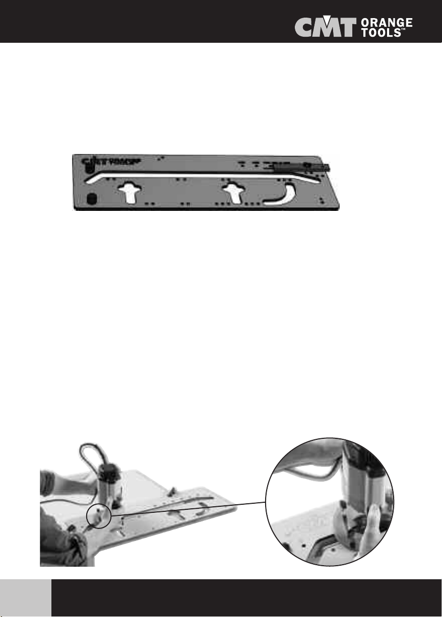
Using the sliding stop:
To position the sliding stop, fit it to the underside of the jig with the clamping screw, secured by the
clamping knob and washer, through the respective groove. Fit two stops in holes B, hold these tight to
the front face of he worktop, checking that the jig is square to it.
Adjust the sliding stop up to the rear edge and tighten the clamp.
Cutting the female edge:
Position the stops in holes C on the jig (See Page 7). There is one stop that sits against the end of the
worktop and two along the front face. The front stops are set in two of the four holes, the width of the
worktop determining the distance apart. Ensure that all stops are tight against the worktop edges befo-
re clamping the jig to the worktop. Ensure that the clamps do not infringe the path of the router.
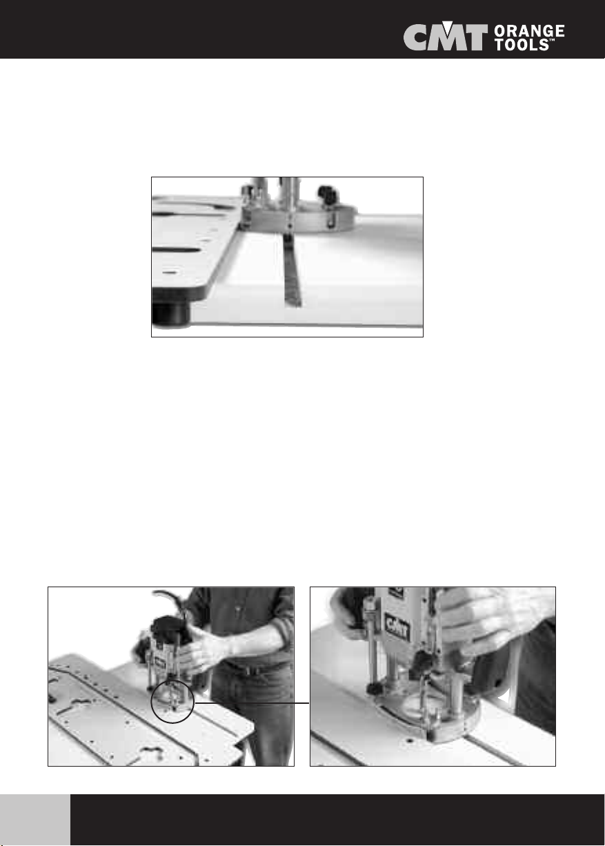
Cutting:
Make the cut in a series of shallow passes, the finer the cut the less effort being placed on the cutter
and the easier it will be to control the router. Keep the feed speed constant and ensure that the rou-
ter remains level on the face of the jig. Always work from left to right, keeping the guide bush against
the edge. To finish, press the guide bush a little harder against the cut edge of the worktop and make
afinal fine pass across the full edge depth.

Cutting 90 degree worktop joints continued...
11
www.cmtutensili.com
Cutting the male section:
First turn and check that the worktop is the correct way up.
When cutting the male edge, leave the sliding width stop or stop Hin position and fit two stops in the
holes B. Position and clamp the jig across the end of the worktop, ensuring that it is square to the front
edge and that the stops are tight against the end. Support the waste end of the worktop to the jig using
aclamp or bysupporting it on a sacrificial work-surface below (to prevent it dropping and tearing the
laminate at the end of the pass). Cut the joint face following the same routing procedure as for the
female cut.
Compensating for out of square walls:
Slight variations can be accommodated with worktop jigs, but only up to approximately 3 degrees
either way. However these joints will never be as precise as a true 90-degree worktop joint. The angle
is always cut on the male section of worktop.
Where possible place the worktops in position with the male section over the female. If space does
not allow this, use a gauge or other method to take off the angle and transfer it to the worktop.
Remember which end you are cutting and turn them face up or down as necessary. Mark the inner
edge of the female section on the underside of the male section. This line will be the cut line for the
angled male section. Turn the male section over and mark the angled line clearly. From this line draw
aline parallel to it and 9mm from it (to allow for the guide bush margin).
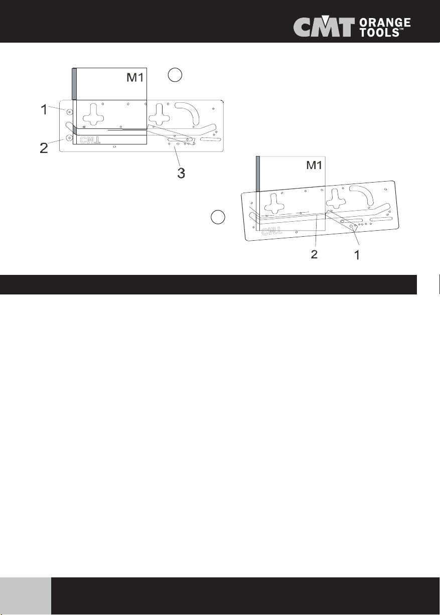
See Diagram A: Fit the two stops into holes Bon the jig and, with the sliding stop loose, position the
jig over the worktop with the two stops against the front edge so that it is square. Check that the stops
are tight against the front edge and clamp the jig to the worktop. Draw a line 9mm parallel to the edge
of the jig. Position the edge of the square sliding stop against the end of this line and tighten the clam-
ping screw.
See Diagram B: Unclamp and remove the two front stops. Lay the jig on the cut line with the point of
the sliding stop on the rear end of the angled cut line. Pivot the jig around this point until the guide edge
is parallel to the angled cut line, but 9mm away from it. Clamp the jig securely to the worktop and cut
the male joint following the routing procedure as before.
Cutting out of square joints...
12 www.cmtutensili.com
A
B
Cutting 45-degree worktop joints...
Tocut 45-degree corner joints on worktops, use the 22.5 mm angled end of the CMT650 jig.
As with 90-degree worktop joints, for 45-degree joints the worktop must be cut with the correct
face upwards depending on whether it is a right or left-hand end or female or male joint edge.
The first step when cutting 45-degree joints is to carefully set out and cut the 45-degree angle on the
relativeend of the worktop (leavethe worktop over length if possible to allow joint to be re-cut if incor-
rect). When cutting worktops to length etc, use a jigsaw to cut away much of the waste to within 3mm
of the required cut line and then trim the cut edge with the router guided against the edge of the jig
or a straight edge. This will leaveastraight square edgeto align the jig stops against.
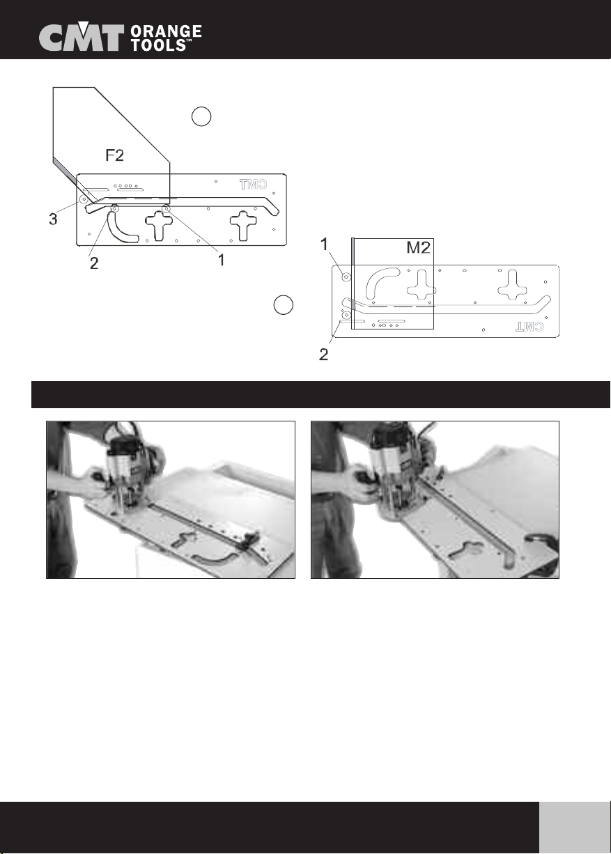
Cutting the female edge (See Fig C):
Inserttwostops into holes Cand one into hole G. Position the jig on the worktop with the Gstop
against the front edge and the Cstops against the angled cut edge. Make the cut with the router fol-
lowing the same procedure as for 90-degree joints.
Cutting the male edge (See Fig D):
Insert the stops into holes A, hold them tight against the front edge of the worktop and clamp the jig
firmly. Make the cut with the router following the same procedure as for 90-degree joints.
Cutting 45-degree worktop joints...
13
www.cmtutensili.com
Tocut the clamp recesses, fit twostops in the jig holes D. The positioning of the clamps should be no
less than 100mm in from the front edgeof the worktop. However the spacing between them can be as
on the jig or altered to suit the worktop width. Remember to match them on both adjoining sections
of worktop, setting-off from the front edge bymeasuring or transfer batten.
Butt the stops against the joint edge and clamp it firmly. Cut the recesses to a depth so that the clamp
bolt is approximately centred on the thickness of the worktop. The same 30mm guide bush and 12mm
cutter is used for this operation, cutting in a series of shallow passes and taking out all of the waste
from the recess.
Cutting the worktop joint clamp recesses...
C
D

Assembly worktop joints...
14 www.cmtutensili.com
Other applications for the CMT650 worktop jig...
When assembling worktop joints it is advisable to insert biscuit dowels (size No 20) to assist in ali-
gning the worktop surfaces and prevent movement between the faces. Recesses for the biscuits can
be cut with the router or a biscuit jointer between the clamp recesses inserting no less than 4 dowels
along a 600mm width of worktop.
For cutting biscuit recesses with the router, use (code 822.340.11) a 4mm thick x 47.6mm slotting
cutter and a 22mm diameter guide bearing (to give a 12.8mm recess (No 20 biscuit is approximate-
ly 24mm wide). [Order no for biscuit joint cutter, arbor and bearing 822.340.11B (1/2” shank) or
822.340.11A (1/4” shank)] or 922.340.11A (shank Ø8mm) or 922.340.11B (shank Ø12mm).
The two cut chipboard faces of the joint must be sealed on assembly to prevent the ingress of water.
This can be done using a fully waterproof adhesive or better, a coloured worktop sealant/adhesive.The
latter are available in a range of colours that can be mixed and matched to blend with the colour of
the worktop laminate. On cheaper worktops it may be found that the chipboard core spreads or bre-
aks-out slightly on cutting. This will need to be trimmed back lightly with abrasive paper before assem-
bly. Take care not to touch the laminate edge when doing this.
Radius corners and 45-degree corners:
To cut radius corners on worktops and peninsular units, insert three stops into holes Emake the cut
with the router in a series of shallowpasses as previously described.

Other applications for the CMT650 worktop jig...
To cut 45-degree corners on worktops and peninsular units, insert two stops into holes Fand make
the cut with the router in a series of shallow passes as previously described.
12Front
15
www.cmtutensili.com

Indice
16 www.cmtutensili.com
¡¡ATENCIÓN!!
Los símbolos utilizados en este manual les aconsejan las protecciones correctas
autilizar durante el trabajo
Símbolos de las protecciones
Indice 58
Contenido de la caja: 59
Herramientas necesarias: 60
Normas de seguridad 61-62
Sistema de junta para encimera de cocina CMT650 63
Instrucciones para la realización de conexiones 64
Realización de una conexión a 90 grados 65-66-67
Realización de conexiones de ángulo recto 68
Realización de conexiones a 45 grados 68-69
Realización de los asientos para los tirantes de la encimera 69
Ensamblaje de la encimera de cocina 70
Otros empleos del CMT650 70-71
G
a
f
a
s
d
e
p
r
o
t
e
c
c
i
ó
n
M
a
s
c
a
r
a
a
n
t
i
p
o
l
v
o
A
u
r
i
c
o
l
a
r
e
s
C
a
s
c
o
d
e
p
r
o
t
e
c
c
i
ó
n
G
u
a
n
t
e
s
d
e
p
r
o
t
e
c
c
i
ó
n
B
o
t
a
s
d
e
s
e
g
u
r
i
d
a
d

Contenido de la caja:
17
www.cmtutensili.com
Código CMT650 Sistema de junta para encimeras de cocina
A
B
D
FE
C
Nr. 1 A Plantilla para encimeras de cocina de fenólico
Nr. 3 B Perno de tope de metal galvanizado
Nr. 1 C Perno de tope deslizable de fenólico
Nr. 1 D Tuerca con arandela de apriete de plástico
Nr. 1 E Bulón M8
Nr.1 F Arandela M8
Nr. 1 Manual de instrucciones

Herramientas necesarias:
18 www.cmtutensili.com
AElectro-fresadora portátil con pinzas de 12 o 12,7 mm
BCamisa de guía Ø30mm (código 899.007.00)
Cllaves y tornillos para fijación camisa de guía
DDos abrazaderas (la mejor solución versión larga con revestimiento suave o
cojinete de protección de la plantilla)
EFresa Ø12mm x 50mm (40mm para placas más sutiles)
FAuriculares, gafas o viseras
B
A
F
D
E
C

Normas de seguridad
19
www.cmtutensili.com
¡Procedimientos correctos de mecanización para vuestra seguridad!
Las sugerencias que les enunciamos a continuación os permitirán respetar los
procedimientos correctos de mecanización y asegurarles una seguridad total y
también les ayudará a conservar las herramientas y equipos en buen estado
para el próximo empleo.
11. Asegúrese de saber usar bien la fresadora eléctrica antes de utilizar el sistema de junta para cocinas
CMT650.
12. Siga siempre las instrucciones suministradas por el fabricante de la fresadora y los proce dimientos
de seguridad.
13. Si es la primera vez que utiliza un sistema de conexión para encimera de cocina, ejecute una serie de
pruebas en piezas de descarte para adquirir mayor confianza con los procedimientos, la secuencia de
los pasos y las características de los tipos de fresado, tanto de los materiales, de la fresadora como
de la plantilla.
14. Use siempre los auriculares y gafas de protección durante el trabajo.
15. Use siempre una mascarilla para el polvo o un respirador y, si es posible, use aparatos para aspirar
el polvo.
16. Evite usar prendas holgadas y los cabellos sueltos.
17. Quite siempre las llaves o pinzas de la fresadora y no las deje sobre el plano de trabajo o en la másca-
ra durante el trabajo.
18. Apague siempre la fresadora y espere que haya dejado de girar antes de alzarla.
19. Fije siempre el plano a una superficie rígida y segura durante la operación de fresado.
10. Si es posible corte siempre las uniones antes de cortar la longitud definitiva.
¡¡ATENCIÓN!!
Mantener las herramientas y los equipos lejos del alcance de los niños

Normas de seguridad
20 www.cmtutensili.com
Fresas y Pinzas
Cuando se realizan encimeras de cocina la naturaleza abrasiva del tablero de
viruta de madera y su revestimiento desgastan rápidamente la hoja de cada
fresa, incluso de aquellas que tienen pastillas de carburo de tungsteno. Es
muy difícil que con una misma fresa pueda realizar más de tres encimeras de
cocina sin que se astillen. Cerciórese siempre que las fresas estén limpias y
afiladas (a mano o con una piedra diamantada).
Cerciórese que la fresa esté fijada correctamente a la pinza de la fresadora.
(ver el manual de instrucciones de la electrofresadora).
Controle siempre que el aro de guía esté centrado respecto a la fresa, use un perno para el centrado.
Table of contents
Languages:
Other CMT ORANGE TOOLS Tools manuals

CMT ORANGE TOOLS
CMT ORANGE TOOLS CMT11 User manual

CMT ORANGE TOOLS
CMT ORANGE TOOLS Industrio Operating instructions

CMT ORANGE TOOLS
CMT ORANGE TOOLS CMT200 Assembly instructions

CMT ORANGE TOOLS
CMT ORANGE TOOLS Pocket-Pro PPJ-001 User manual

CMT ORANGE TOOLS
CMT ORANGE TOOLS CMT792 User manual

CMT ORANGE TOOLS
CMT ORANGE TOOLS 230.312.08M Use and care manual
Popular Tools manuals by other brands


Sealey
Sealey Auto Service VSE127H instructions

Tramontina
Tramontina 78594/000 Assembling Procedure

Pattfield Ergo Tools
Pattfield Ergo Tools PE-500PF Original instructions

CLEAN ROOM DEVICES
CLEAN ROOM DEVICES CRD 410 Operation manual

SPX
SPX StrutTamer 6070A operating instructions

Parkside
Parkside PSS 65 A1 Original instructions


