CNB NB21-7MHR-6 User manual
MB12-7MH
Owner’s Manual
NB21-7MHR-6
Fusion IR Full HD Bullet IP Camera
N
NB
B2
21
1-
-7
7M
MH
HR
R-
-6
6
U
Us
se
er
r’
’s
s
G
Gu
ui
id
de
e
2
Rev.1.4
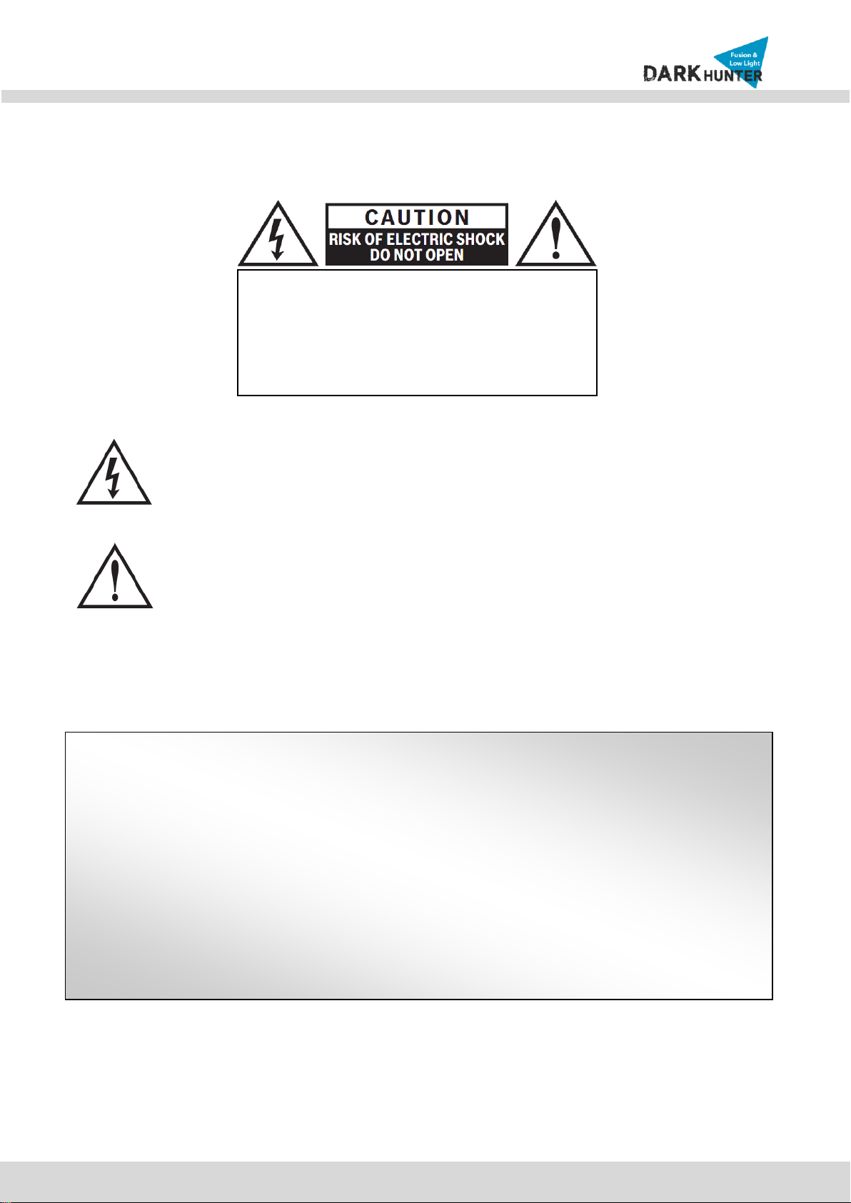
The lightning flash with arrowhead symbol, within an equilateral triangle, is
intended to alert the user to the presence of uninsulated “dangerous voltage"
within the product's enclosure that may be of sufficient magnitude to constitute
a risk of electric shock to persons.
The exclamation point within an equilateral triangle is intended to alert the user to
the presence of important operating and maintenance (servicing) instructions in
the literature accompanying the appliance.
THE GRAPHIC SYMBOLS WITH SUPPLEMENTAL MARKING ARE ON THE BOTTOM OF THE SYSTEM.
"WARNING-TO PREVENT FIRE OR SHOCK HAZARD, DO NOT EXPOSE THE UNIT TO RAIN OR MOISTURE"
Directions
Be careful not to cause any physical damage by dropping or throwing IP Camera. Especially keep
the device away from children.
Do not disassemble IP Camera. No After Service is assumed when disassembled.
Use only the power adapter provided with IP Camera.
Be careful to prevent moisture or water penetration into the unit. Particular attention is needed
when installing IP Camera. The screw holes for the installation screws and pipes should be
maintained tight during the whole life time of the product.
All the electrical connection wires plugging in the unit should be prepared so that water from the
outside cannot flow into the unit through the surface of the wires. Penetration of the moisture
through the wire for extended period can cause malfunction of the unit or deteriorated image.
CAUTION!
TO REDUCE THE RISK OF ELECTRIC SHOCK, DO
NOT REMOVE COVER (OR BACK). NO USER
SERVICEABLE PARTS INSIDE. REFER SERVICING
TO QUALIFIED SERVICE PERSONNEL.
MB12-7MH
Owner’s Manual

N
NB
B2
21
1-
-7
7M
MH
HR
R-
-6
6
U
Us
se
er
r’
’s
s
G
Gu
ui
id
de
e
3
Rev.1.4
CAUTION!
Changes or modifications not expressly approved by the manufacturer could void the user's
authority to operate the equipment.
Regulatory Notice
This equipment has been tested and found to comply with limits for a Class of digital device,
pursuant to part 15 of the FCC Rules. These limits are designed to provide reasonable protection
against harmful interference when the equipment is operated in a commercial environment.
This equipment generates, uses, and can radiate radio frequency energy and, if not installed and
used in accordance with the instruction manual, may cause harmful interference to radio
communications. Operation of this equipment in a residential area is likely to cause harmful
interference in which case the user will be required to correct the interference at their own
expense.

N
NB
B2
21
1-
-7
7M
MH
HR
R-
-6
6
U
Us
se
er
r’
’s
s
G
Gu
ui
id
de
e
4
Rev.1.4
Contents
1. Introduction....................................................................................................................................................5
1.1. Overview...............................................................................................................................................5
1.2. Features & Specification.......................................................................................................................6
1.2.1.
F
Fe
ea
at
tu
ur
re
es
s
......................................................................................................................................6
1
1.
.2
2.
.2
2.
.
S
Sp
pe
ec
ci
if
fi
ic
ca
at
ti
io
on
n
................................................................................................................................6
1.3. Applications of IP Camera ....................................................................................................................9
2. Product Description ....................................................................................................................................10
2.1. Contents..............................................................................................................................................10
2.2. Camera mount configuration...............................................................................................................10
2.3. Product Preview..................................................................................................................................11
2.4. Physical description ............................................................................................................................11
2.4.1. External View............................................................................................................................11
2.4.2. Dimension.................................................................................................................................12
2.4.3. External Connector...................................................................................................................12
2.4.4. Factory Default Switch..............................................................................................................12
2.5. Functional Description ........................................................................................................................13
3. On Site Installation ......................................................................................................................................15
4. Getting Started.............................................................................................................................................17
4.1. PC Requirement .................................................................................................................................17
4.2. Quick Installation Guide......................................................................................................................17
4.2.1. Connect PC and IP Camera to network. ..................................................................................17
4.2.2. Install IP installer and set IP parameters on IP Camera...........................................................18
4.2.3. Remote video connection to IP Camera...................................................................................21
4.2.4. Additional settings through connection to the Admin Page......................................................22
5. Troubleshooting...........................................................................................................................................23
5.1. No power.............................................................................................................................................23
5.2. Cannot connect to the Video...............................................................................................................23
5.3. Windows 7 ..........................................................................................................................................24
5.4. Technical Assistance...........................................................................................................................25
AppendixA–Important Noticein ExchangingSD Card(MicroSD).........................................................................26

N
NB
B2
21
1-
-7
7M
MH
HR
R-
-6
6
U
Us
se
er
r’
’s
s
G
Gu
ui
id
de
e
5
Rev.1.4
1. Introduction
1.1. Overview
The product is multi-codec (H.264, MJPEG) IP camera (or network camera) built with embedded software and
hardware technology. It enables real time transmission of synchronized video up to 1,080P and audio data.
Remote clients can connect to IP Camera for the real time video/audio data through various client solutions
running on PC or smart device. Real time 2-way communication is available through bidirectional audio
communication feature.
Dark Hunter technology is the most optimized solution for indoor and outdoor surveillance in low-light conditions
by using superior CMOS sensor with low-light sensitivity ISP sensor.
Furthermore, it can get much vivid image using Super IR LED in extremely low light conditions compared with
using conventional IR LED.
Designed to be a stand-alone streaming audio & video transmission device, the product can be applied to
various application area such as video security, remote video monitoring, distance education, video conference
or internet broadcasting system.
Vandal proof and weather proof housing will extend the application area to harsh environment of wide
temperature range. Embedded PoE (Power of Ethernet, IEEE 802.3af) will enable the owner to reduce TCO
(Total Cost of Ownership) by reducing on-site wiring works for the installation.
N
NB
B2
21
1-
-7
7M
MH
HR
R-
-6
6
U
Us
se
er
r’
’s
s
G
Gu
ui
id
de
e
6
Rev.1.4
1.2. Features & Specification
1.2.1.
F
Fe
ea
at
tu
ur
re
es
s
H.264MP IP Camera
Fusion IR Full HD Bullet IP Camera
1/3” Progressive scan CMOS Sensor
Dual-Codec (H.264MP/MJPEG)
Progressive scan megapixel (2M CMOS)
Multi profile streaming
(5 different streams per Resolution, Frame, Rate, Codec)
Digital PTZ, video crop
Analog video output (CVBS)
Built-in standard PoE
Two-way audio communication
Dark Hunter + Super IR LED
Compact design & Easy installation
Vandal proof, Weather proof (IP66)
1
1.
.2
2.
.2
2.
.
S
Sp
pe
ec
ci
if
fi
ic
ca
at
ti
io
on
n
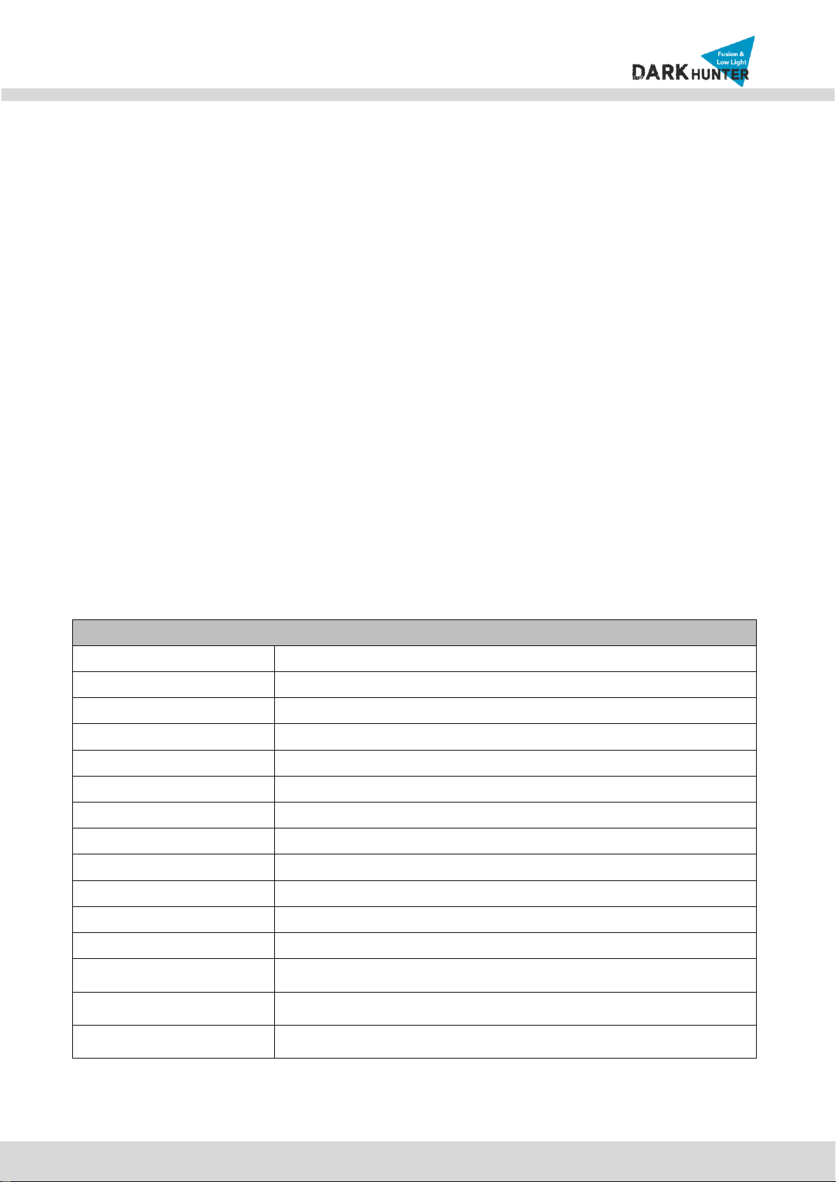
Camera
Image sensor
Progressive scan 1/3 inch CMOS 2M pixels
Full resolution
1,920 x 1,080 pixels (Full HD)
Sync System
Internal
Lens
6mm Fixed
Day & Night
AUTO, DAY, NIGHT
Sensitivity
Color : to 0.04Lux, B/W : 0Lux(IR ON)
Back Light Compensation
ON / OFF
White Balance
ATW(2.000K ~ 10,000K) / MANUAL / PUSH
Exposure
DC / ESC
WDR
ON / OFF
3D-DNR
0 ~ 20
Dark Hunter
AUTO ON (Max. x32) / OFF
Privacy Mask
ON / OFF (1 Programmable Zone)
Motion Detection
ON / OFF (3 Programmable Zone)
Digital Zoom
X1 ~ X12
N
NB
B2
21
1-
-7
7M
MH
HR
R-
-6
6
U
Us
se
er
r’
’s
s
G
Gu
ui
id
de
e
7
Rev.1.4
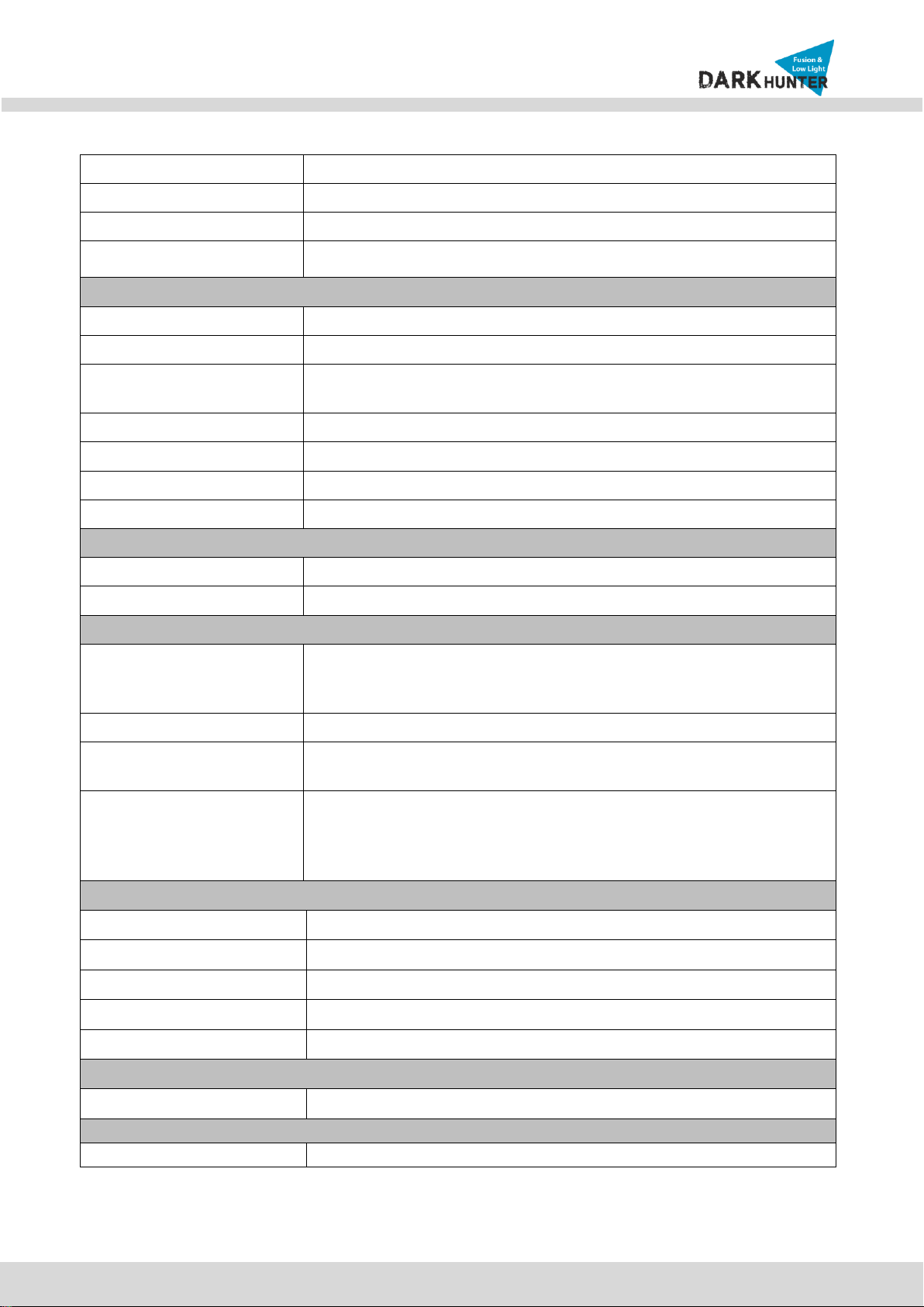
Mirror
H / V / Rotate
DEFOG
ON / OFF
OSD
BUILT IN
Super IR LED
2EA
Video
Compression method
Simultaneous Dual Codec (H.264MP / MJPEG)
Resolution
1,920 x 1,080@30fps
Multi-Profile Streaming
- 5 simultaneous video profiles
- Select the codec type, resolution and frame rates for each profile.
Intelligent Bit-Rate Control
Hybrid Bit Rate control (VBR+CBR)
PTZ
Digital PTZ & Video crop
Image Setting
Text overlay, Privacy mask, De-interlace filter
Motion detection
3 regions
Audio
Mono Upstream
32Kbps G.726 ADPCM, 64Kbps 16bit μ-law PCM ~ MIC/Line-in
Mono Downstream
64Kbps 16bit μ-law PCM ~ Line-out
Network
Network Protocol
- IPv4, TCP/IP, UDP, IGMP, ICMP, ARP, RARP, PPPoE, RTCP
- RTP, RTSP, SDP, HTTP, SMTP, FTP, DHCP, UPnP
- NTP, DNS, DynDNS
Dynamic IP
Supported
Security
- User ID & Password protection, IP address filtering
- Digest Authentication, User Access Log
Streaming method
- RTSP streaming with proprietary format for control information
- standard RTSP streaming
- HTTP streaming
- Onvif Profile-S
External Terminals
LAN
10/100BaseT LAN (auto MDIX)
Analog output
1 channel D1 CVBS output of the encoding video
Alarm input / output
Alarm I/O (1 Sensor input & 1 Relay output)
Factory Reset
Supported
Other
MIC, Line in / Line out / DC 12V in
Installation
Standard PoE
IEEE802.3af Supported
System Integration
Intelligent Video
Motion Detection

N
NB
B2
21
1-
-7
7M
MH
HR
R-
-6
6
U
Us
se
er
r’
’s
s
G
Gu
ui
id
de
e
8
Rev.1.4
Alarm Triggers
Motion Detection + Sensor Input +Audio Detection
Alarm Events
Video file upload(FTP), Still Image transmission(Email), Relay output
Alarm Buffer (Audio/Video)
Configurable Pre-alarm (5~15 sec) & Post-alarm (10~60 sec)
Operating Environment, Power, Dimensions
Operating Temperature
-10C ~ 50C
Operation Humidity
8 ~ 80% RH
Power
DC 12V, 0.6A
Dimensions(W x H x D)
Ø 99mm x 252.7mm
Weight
1.1kg
Casing
AL, PC, IP66
Approvals
FCC, CE, KC
Package information
IP camera, CD (User’s guide, Software…)
Client Software
NVR2
64ch (free of charge)
Mobile
Android, iOS (free of charge)
Optional Items
Local storage
Micro SD card
Adapter
DC 12V, 1.5A

N
NB
B2
21
1-
-7
7M
MH
HR
R-
-6
6
U
Us
se
er
r’
’s
s
G
Gu
ui
id
de
e
9
Rev.1.4
1.3. Applications of IP Camera
Security surveillance (buildings, stores, manufacturing facilities, parking lots, banks, government facilities,
military, etc.)
Remote monitoring (hospitals, kindergartens, traffic, public areas, etc.)
Teleconference (Bi-directional audio conference). Remote Learning, Internet broadcasting
Weather and environmental observation
N
NB
B2
21
1-
-7
7M
MH
HR
R-
-6
6
U
Us
se
er
r’
’s
s
G
Gu
ui
id
de
e
10
Rev.1.4
2. Product Description
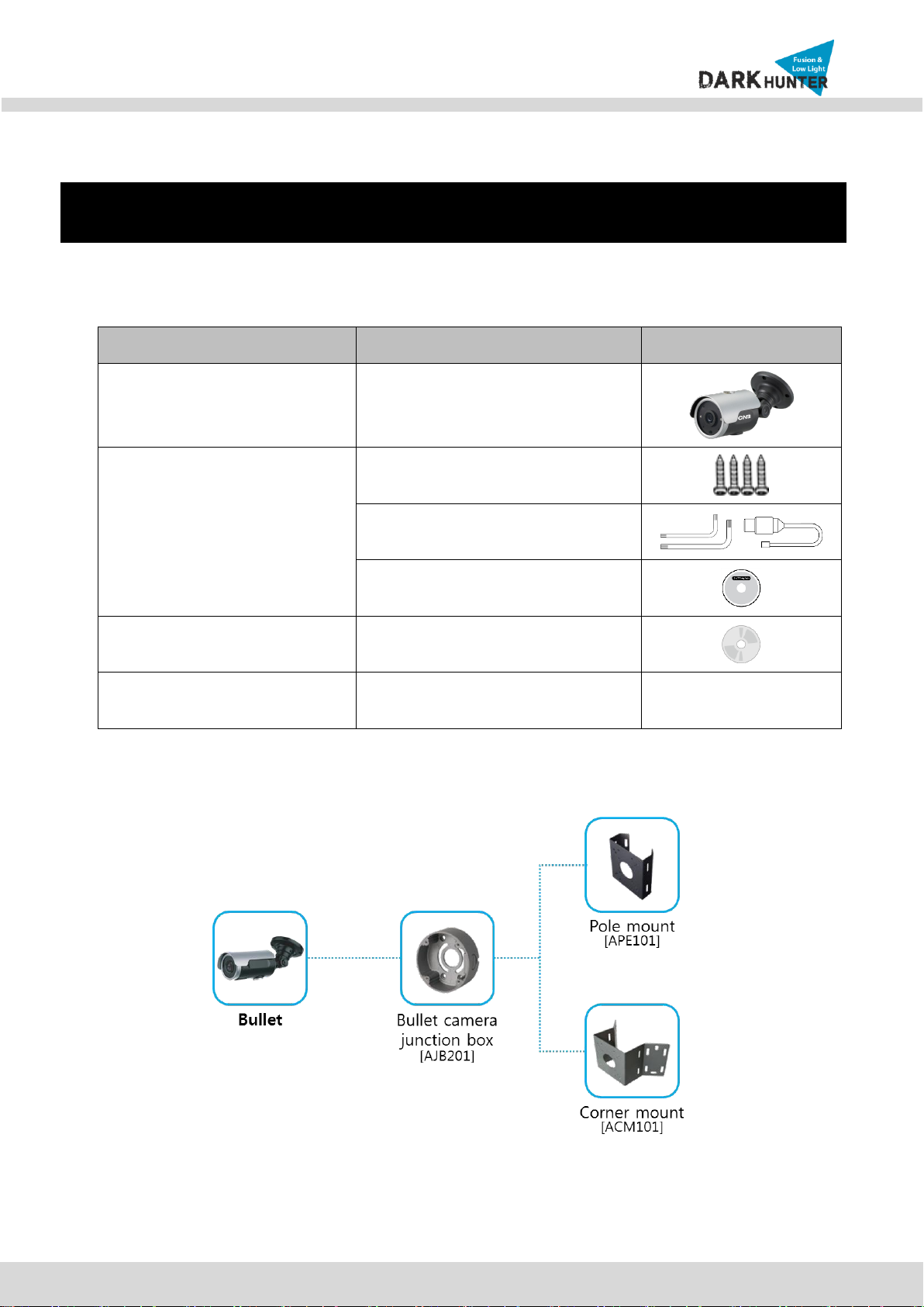
2.1. Contents
The product package contains followings:
Contents
Description
Remarks
IP Camera
NB21-7MHR-6 main unit
Accessories
Screws
L-type wrench, CVBS Cable
Guide pattern
CD
Software & User’s Guide
Power Adaptor
Default built in standard PoE module
(IEEE802.3af)
12V DC Adaptor
(Optional item)
2.2. Camera mount configuration

N
NB
B2
21
1-
-7
7M
MH
HR
R-
-6
6
U
Us
se
er
r’
’s
s
G
Gu
ui
id
de
e
11
Rev.1.4
2.3. Product Preview
IP Camera
IP-Installer
CMS Software (NVR)
NB21-7MHR-6
PC software to allocate an IP
address to the IP Camera
PC software to view and record the
A/V streaming data transmitted from
IP camera.
(Simultaneous support of up to 64
IP cameras)
2.4. Physical description
2.4.1. External View
Figure 2-1. External view of IP Camera
N
NB
B2
21
1-
-7
7M
MH
HR
R-
-6
6
U
Us
se
er
r’
’s
s
G
Gu
ui
id
de
e
12
Rev.1.4
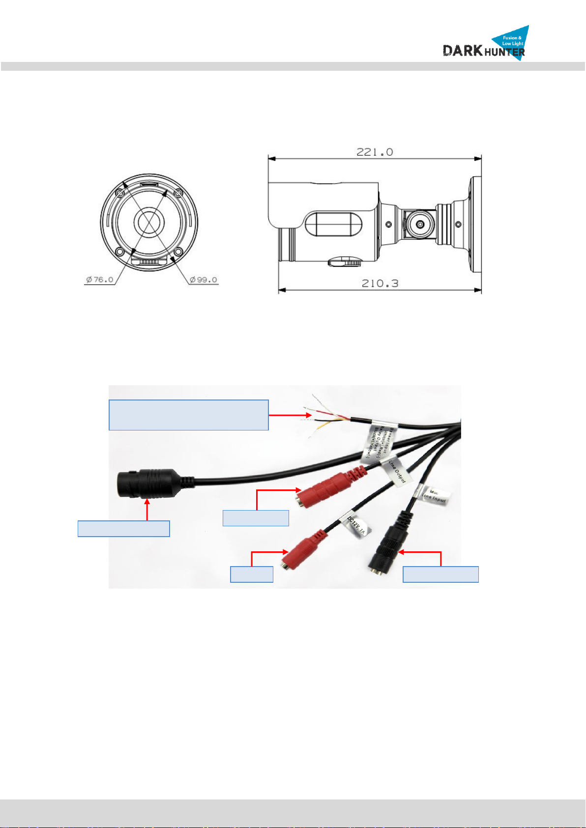
2.4.2. Dimension
Figure 2-2. Dimension
2.4.3. External Connector
Figure 2-3. Connector for external connection
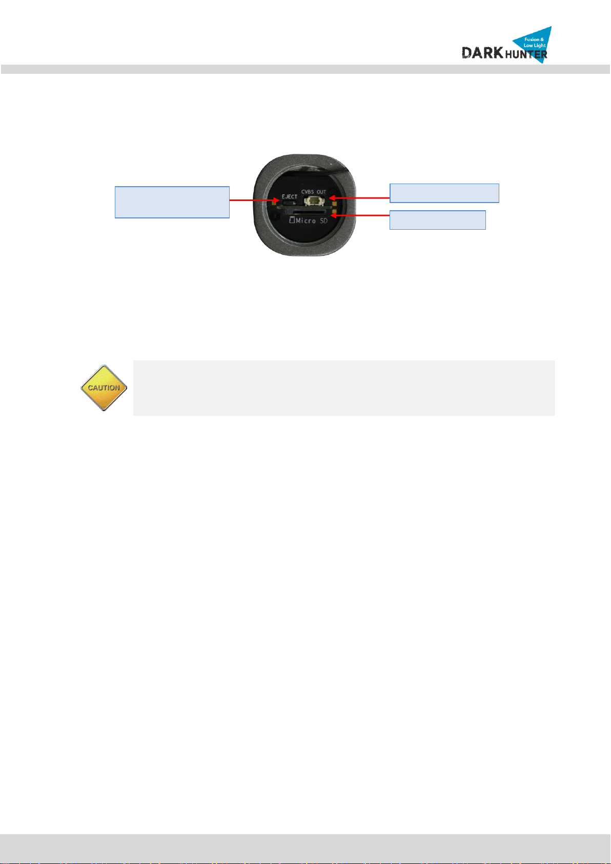
2.4.4. Factory Default Switch
Factory default switch is provided for returning the IP camera to factory default state. The factory default
switch can be found by opening the lower body cap of the camera. There are two functions assigned to
factory default switch.
1. Returning to Factory Default State : Press the switch about 5 seconds while power is applied to return
to factory default state.
Network (LAN)
Power
Mic/Line Input
Line Output
Sensor Input (white(+), Red(-))
Relay Output (Black(+), Yellow(-))
Unit: mm
N
NB
B2
21
1-
-7
7M
MH
HR
R-
-6
6
U
Us
se
er
r’
’s
s
G
Gu
ui
id
de
e
13
Rev.1.4
2. Safe Removal of Micro-SD Card : Press the switch for 1 second to unmount Micro-SD Card for safe
removal.
Figure 2-4. Factory Default switch and Micro-SD Card slot
2.5. Functional Description
Power : Power input for supplying 12V DC power.
Caution : If IP Camera is powered by PoE, do not plug in DC Jack with active DC
power into DC power connector.
Network (LAN)
100Mbps Ethernet connector (RJ-45) with PoE standard (802.3af).
MIC/Line Input
Connect external audio source or microphone.
Micro SD Card slot
Please insert SD memory card when you want to use SD memory card. In case of pulling out SD memory
card, please push the SD card.
Line Output
Connect speakers with built in amplifier. Audio from remote site is output through line out in bi-directional
audio mode.
Factory Default Switch/
Micro SD Card Eject
Micro SD Card Slot
Video Output (CVBS)
N
NB
B2
21
1-
-7
7M
MH
HR
R-
-6
6
U
Us
se
er
r’
’s
s
G
Gu
ui
id
de
e
14
Rev.1.4
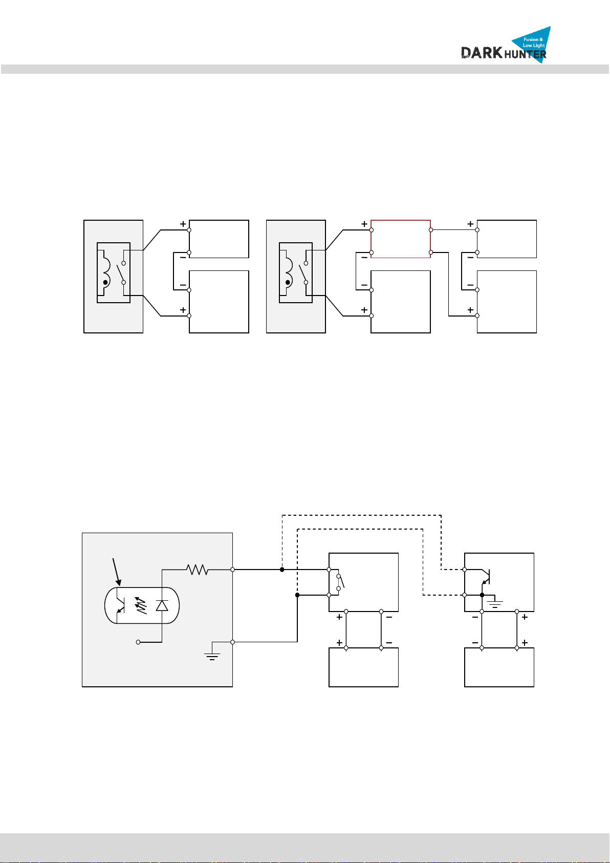
Relay Output
Relay output is provided for connecting alarm devices or for remote on/off control of devices such as light.
Relay is normal open and it will be closed upon alarm annunciation or remote on. The relay is capable
of switching 30V AC/DC, 2A. For the application which needs power switching beyond this limit, use
additional relay switch as shown in the right of Figure 2-5.
* Left : switching requirement below 30V, 2A
* Right : switching requirement higher than 30V, 2A. Apply this connection when either voltage or
current exceed the limit.
Figure 2-5. RELAY Output connection
Sensor Input
Connect external alarm sensor. Examples of sensing devices are infrared sensor, motion sensor,
heat/smoke sensor, magnetic sensor, etc. Connect the two wires of the sensors to “SNS In”. The sensor
type(NC/NO) can be set in admin page. Multiple sensor devices can be connected in parallel.
Figure 2-6. SENSOR input and connection of the sensor
Alarm
Out
Device
Power
Supply
( ~30V)
( ~ 2A)
(DC/AC)
Alarm
Out
Device
Power
Supply
(30V~ )
( 2A~ )
(DC/AC)
Optional
Relay
Switch
Power
Supply
( ~30V)
( ~ 2A)
(DC/AC)
Relay
Relay
Photo Coupler
NO/NC Type
Open Collector Type
Sensor1+
Sensor
Device
Sensor1-
Sensor
Device
Sensor
Power
Supply
Sensor
Power
Supply
GND
+12V

N
NB
B2
21
1-
-7
7M
MH
HR
R-
-6
6
U
Us
se
er
r’
’s
s
G
Gu
ui
id
de
e
15
Rev.1.4
3. On Site Installation
Use cables and conduits that are suitable for the installation and that are compliant to IP66. Particular attention
should be paid in the installation so that no moisture is allowed to penetrate into the unit through the cables or
conduits during the life time of the product. Products of which the internal parts are exposed to moisture
because of improper installation are not covered by warranty. Follow the procedure below for proper installation
1. Fix the base on the wall.
2. Adjust the rotational position of the camera for desired viewing of the site.
N
NB
B2
21
1-
-7
7M
MH
HR
R-
-6
6
U
Us
se
er
r’
’s
s
G
Gu
ui
id
de
e
16
Rev.1.4
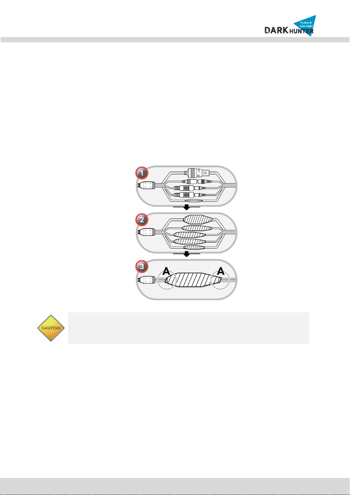
Precautions –Outdoor Installation
: Leaking expected at connected cable on outdoor installation.
Use the waterproof rubber tape winding up on cable connection as following picture.
1) Connect cables.
2) Winding rubber tape with half overlay on external cable jacket (A) and cable connection.
The tape material butyl rubber is extended more than double size.
Winding tightly cable connection to prevent leaking on cable.
This product is IP66 waterproof certified one but the external cable connection part
is not waterproof. Do not expose cable on dropping water or humid place and be
sure to wring waterproof rubber tape.
N
NB
B2
21
1-
-7
7M
MH
HR
R-
-6
6
U
Us
se
er
r’
’s
s
G
Gu
ui
id
de
e
17
Rev.1.4
4. Getting Started
4.1. PC Requirement
Audio/Video streaming data received from IP Camera can be displayed or stored in a PC running client
programs. Minimum requirement of the PC is described below:
Minimum Requirement
Recommended Specification
CPU
Intel Core i3 3Ghz
Intel Core i7
Main Memory
2GB
4GB
Operating System*
Windows XP
Windows 7 (64bit)
Web Browser
Internet Explorer 8, 9
Internet Explorer 8, 9
Graphic Card
Video RAM 256MB
Resolution 1920x1080
Video RAM 1GB
Higher than 1920x1080
Network
10 Base-T Ethernet
100 Base-T Ethernet
* Operating Systems supported: Windows 2000 Professional, Windows XP / Vista / 7
4.2. Quick Installation Guide
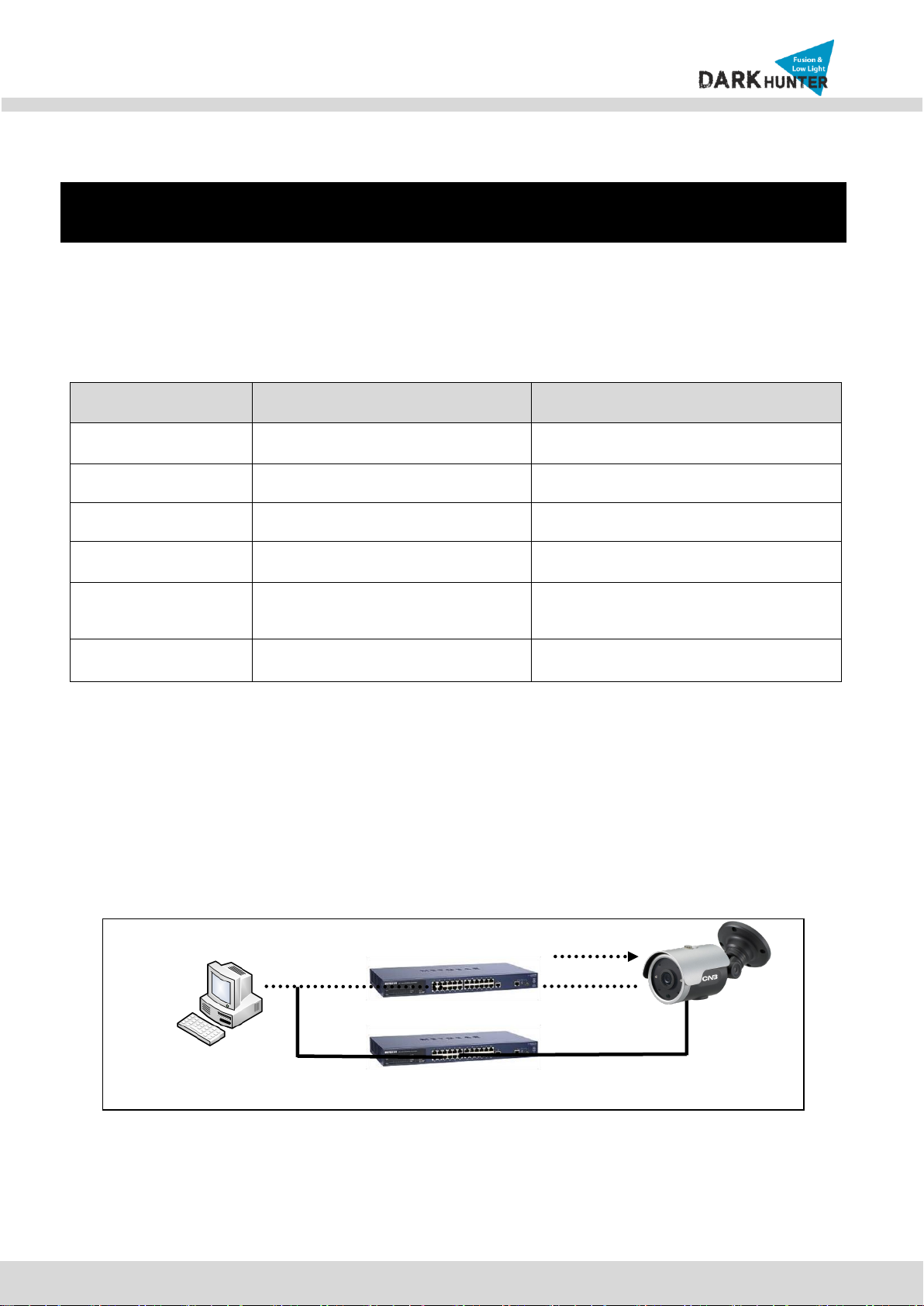
4.2.1. Connect PC and IP Camera to network.
1. Prepare a PC to run programs for the installation and video connection
(PC is needed to assign IP address to IP Camera)
2. Connect IP Camera as shown in dotted line in Figure 4-1. The DC power through DC adaptor is no
need to connect if LAN switch supports PoE (IEEE802.3af).
Figure 4-1. Power and network connection
LAN switch with
standard POE
(802.3af)
LAN switch
DC adaptor

N
NB
B2
21
1-
-7
7M
MH
HR
R-
-6
6
U
Us
se
er
r’
’s
s
G
Gu
ui
id
de
e
18
Rev.1.4
4.2.2. Install IP installer and set IP parameters on IP Camera
1. Please insert the Setup CD into your CD-ROM drive, and then please setup
Figure 4-2-1. IP Installer Setup 1
2. Please click ‘Install’ button to begin the Installation.
Figure 4-2-2. IP Installer Setup 2
3. Please click ‘Finish’ button to complete the installation.
Figure 4-2-3. IP Installer Setup 3

N
NB
B2
21
1-
-7
7M
MH
HR
R-
-6
6
U
Us
se
er
r’
’s
s
G
Gu
ui
id
de
e
19
Rev.1.4
4. XNET IP Installer program is automatically launched like below right after the program installation.
Figure 4-2-4. IP Installer Start box
5. Select the camera of which you wish to change the IP address and click (Set IP Address) button
to bring up the following box in Figure 4-2-5.
Figure 4-2-5. IP Address box

N
NB
B2
21
1-
-7
7M
MH
HR
R-
-6
6
U
Us
se
er
r’
’s
s
G
Gu
ui
id
de
e
20
Rev.1.4
6. When you enter the IP address and click Set button, the box shown in Figure 4-2-5 will appear.
Figure 4-2-6. Select Network Adapter Box
7. Select the adapter and click ‘Select’button to change the IP address of the camera.
This manual suits for next models
1
Other CNB Security Camera manuals


CNB
CNB IPM3063N User manual

CNB
CNB XNET NDE5055MF User manual

CNB
CNB TPM24R-X44SW User manual

CNB
CNB IDC4050IR User manual

CNB
CNB XNET IGP1030 User manual

CNB
CNB IDC4050IR User manual

CNB
CNB IDP4030VR User manual

CNB
CNB XPEED Indoor Series User manual

CNB
CNB XNET IVC5055VR User manual

CNB
CNB Xpeed s2000 series User manual


