CNB XNET IBP5030CR User manual

Ver. 1.0
XNET
(IBP5030CR)
Installation Manual

Network Weatherproof Camera Installation Manual
2/ 20
About this Installation Manual
A compatibility and durability test ensured this product’s high performance.
This installation manual is for XNET Network Weatherproof Camera users only, and it
describes operations related to XNET Network Weatherproof Camera.
Please read this manual thoroughly paying attention to cautions and warnings before
using the product even if you have used similar products before.
Important Notices
The copyright of this manual is owned by CNB Technology Inc.
It is illegal to copy and distribute this manual without permission.
Damages caused by use of not suggested parts and misuse will not be applicable for
support.
Contact the store or the manufacturer immediately if (you think) there is any problem
with the product.
Contact the store or the manufacturer before disassembling the product for alteration
or repair.
XNET is a trademark of CNB Technology Inc.
This product complies for CE (Europe) and FCC (USA) regulations for industrial/home
use electrical device.
INFORMATION
This equipment has been tested and found to comply with the limits for a Class A
digital device, pursuant to Part 15 of the FCC Rules. These limits are designed to
provide reasonable protection against harmful interference when the equipment is
operated in a commercial environment. This equipment generates, uses and can
radiate radio frequency energy and, if not installed and used in accordance with the
instruction manual, may cause harmful interference to radio communications.
Operation of this equipment in a residential area is likely to cause harmful
interference in which case the user will be required to correct the interference at his
own expense.

Network Weatherproof Camera Installation Manual
3/ 20
Index
1. About XNET...................................................................................................................... 4
1.1. About XNET ............................................................................................................................. 4
1.2. XNET - Highlights..................................................................................................................... 4
1.3. XNET Applications.................................................................................................................... 4
2. About the Product ........................................................................................................... 5
2.1 Contents.................................................................................................................................... 5
2.2 Product Information................................................................................................................... 5
2.3 Hardware................................................................................................................................... 6
2.3.1 Hardware Designation................................................................................................................. 6
2.3.2 Camera Module – Rear............................................................................................................... 7
2.3.3 Cable Connection........................................................................................................................ 8
2.3.4 Network Cable............................................................................................................................. 9
2.3.5 Adjusting Zoom and Focus ....................................................................................................... 10
2.3.6 Connection to Alarm Devices.................................................................................................... 10
2.3.7 Mounting the Camera................................................................................................................ 11
3. Software Installation...................................................................................................... 12
3.1. Connecting XNET to network ................................................................................................. 12
3.2. Installing IP-Installer Software and Configuring IP address ................................................... 13
3.2.1. About IP-Installer...................................................................................................................... 13
3.2.2. IP Address Configuration ......................................................................................................... 13
4. Using Web Viewer.......................................................................................................... 15
4.1. Logging In .............................................................................................................................. 15
4.2. Web Viewer Page................................................................................................................... 17
5. Specifications ................................................................................................................ 19

Network Weatherproof Camera Installation Manual
4/ 20
1. About XNET
1.1. About XNET
XNET is an internet based surveillance system that is compatible with various network conditions through
easy installation, user interface, and multi-Codec such as MJPEG, MPEG-4, and H.264.
XNET provides stable real-time surveillance by monitoring live mega pixel video and audio with local
storage (in case of any network problems) and hybrid IP technology that can be integrated into the existing
analog CCTV systems.
1.2. XNET - Highlights
Progressive technology
Progressive scan produces a sharp and clear image on moving objects, preventing a ghost effect.
Hybrid IP Technology
Analog video output can be used for any previously established analog CCTV systems.
Multi-CoDec streaming
Live video streaming can be done using MJPEG or MPEG-4(or H.264) to meet various network
requirements.
Smart Event feature
In addition to motion detection and sensor/alarm feature, pre- and post- alarm feature allows fully
automated surveillance without an operator.
Install/ Operation Wizard
Install/ Operation Wizard makes it easy to install and run the system, and it also offers a unified setup
configuration for large and multiple installation projects.
Up to 3 motion detection areas
Motion Detection – Alarm output and Video/ Audio transmission to an FTP site by e-mail
Various resolutions
- SXGA (1280x960), XGA (1024x768), VGA (640x480), and CIF (320x240)
Control over the network for firmware upgrade and menu settings
1.3. XNET Applications
ySurveillance (Building, store, factory, parking lot, financial institutions, government buildings, military
facilities, etc.)
yRemote video monitoring (Hospital, kindergarten, traffic monitoring, remote branch office, weather,
environment preservation, and illegal disposal of trash, etc.)
yReal time broadcasting over the internet (Resort facility, parties, festivals, etc), business meetings,
educational trainings over the network, and much more.

Network Weatherproof Camera Installation Manual
5/ 20
2. About the Product
2.1 Contents
Please make sure that no contents listed below are missing in the package.
IBP5030CR PRODUCT
SUNVISOR
L Wrench
BOLT AND SCREW
BRACKET SUPPORT
Adaptor and Power Cable
Power and Video
Terminal
RJ45 SCREW
CD
2.2 Product Information
XNET
(IBP5030CR)
Install CD
IP-Installer
Viewer Program (XNET-NVR)
Network Weatherproof
Camera
assigns an IP address to the XNET
product
A PC software that monitors and
records Video signal from the XNET
device (up to 16 channels)

Network Weatherproof Camera Installation Manual
6/ 20
2.3 Hardware
2.3.1 Hardware Designation
Complete System
①Sunvisor fix Screw: Fixes Sunvisor on the Camera
②Photo Sensor
③IR Illuminator : automatically illuminates depending on the light intensity
④Sunvisor : Protects the camera against rain, snow, and direct sunlight
⑤Screws (front-4EA & rear-4EA)
Sets the front and back cap
⑥FRONT Cap
⑦MAIN BODY
⑧REAR Cap
⑨Pan adjusting Screw : fixes the pan angle of the camera
⑩Tilt adjusting Screw : fixes the tilt angle of the camera
⑪Mounting Bracket Screw
⑫Screw for Wall Mount Bracket Base Adapter
⑬Bracket Support
⑭IR Illuminator Support

Network Weatherproof Camera Installation Manual
7/ 20
2.3.2 Camera Module – Rear
As shown in the picture above, open up the rear cap by undoing the four screws on the corners.
Main body
Rear body
①Illuminator Control Connector : controls the IR LED units
②Factory Reset Button : Press and hold for more than 3 seconds while power is on to recall factory
default settings
③Video Out Jack : Analog Video output. Use this output to monitor the analog video signal during
installation.
(Enable Video Out at menu screen to turn this video on)
④CABLE IN 1 ( Alarm / Sensor / Power IN / Video out ) – [ Class 1 Only ]
Alarm Input/ Output, DC12V Input, and Analog Video Output
⑤CABLE IN 2 ( RS485/Power IN/Video out ) – [ Class 2 Only ]
This connects to control P/T(Pan/Tilt) device by RS485 interface
⑥Network Input Cable: Ethernet Input. Connects to a 10Mbps or 100Mbps LAN via waterproof RJ45
Connector.
ⒶPower LED : Lights up Red when 12V DC power is connected.
ⒷLink LED : Lights up Yellow when the network is properly connected.
ⒸACT LED : Lights up Green when the XNET is connected to 100Mbps LAN. Will not light up at 10Mbps
LAN. This will also blink green when there is a network collision.
ⒹSYSTEM LED : Blinks Green to indicate a normal operation.
ⒺEVENT LED : Lights up Green when ALRAM OUT is activated.

Network Weatherproof Camera Installation Manual
8/ 20
2.3.3 Cable Connection
zPower Input(#1, #2)
Use the cable adapter in the package to connect power.
Red –+12V DC, Black - GND
Please use the accessory power supply provided in the package. (DC12V/5A)
zAnalog Video Output (#7, #8)
Use this output for immediate monitoring of the video during installation.
Use the supplied cable adapter (Yellow for video and White for Video GrounGGND)
This adapter can be connected to a cable through a BNC termination.
(Select Video Out at menu screen to enable this output)
zAlarm Connection (Class 1 ONLY)
These wires connect to Alarm input/output devices.
Alarm Sensor Input: Connect to Alarm sensor devices such as IR Sensor or Heat sensor. These can
be configured to normally close or normally open operation. (#5, #6)
Alarm Output: Connect to Alarm devices such as Relay operated Siren Lamp or Alarm Light.
These can be configured to normally close or normally open operation. (#3, #4)
Please refer to “2.3.6 Connection to Alarm Devices” for detailed instruction on how to connect
sensors and Relays.
zRS-485
Open up the rear cap. Connect the cable from Class 1 to Class 2.
This is to control P/T(Pan/Tilt) device by RS485 interface

Network Weatherproof Camera Installation Manual
9/ 20
2.3.4 Network Cable
The waterproof cable from the product can be connected to a 10Mbps or 100Mbps Ethernet, and it uses
a standard RJ-45 connector.
Please follow the order listed below for network connection.
1. Cut the outer Jack of the
Ethernet cable as shown below.
(Recommended cable:
24AWG)
2. Insert Housing into Screw
Nut
3. Insert Seal into the Housing
4. Insert the Ethernet cable from
A and put Sealing Nut onto the
Housing
5. Terminate the Ethernet
cable with RJ45 Plug.
6. Push RJ45 into the Housing and
tighten the Sealing Nut
7. Put in the Gasket into the
Housing
8. Connect RJ 45 to the Ethernet Cable and tighten the Screw nut

Network Weatherproof Camera Installation Manual
10 / 20
2.3.5 Adjusting Zoom and Focus
As shown in the picture below, open up the front cap by undoing the four screws on the corners.
Loosen the zoom and focus fix lever for adjustment, and tighten them back after.
Focus Handle
Use this lever to adjust the focus of the Lens
Zoom Handle
Use this lever to adjust the zoom magnification of the Lens
When you are done with zoom/ focus adjustment, put the front cap back by tightening the four screws on
the corner.
2.3.6 Connection to Alarm Devices
zAlarm Input
Connect wires from Alarm sensors (IR, Heat, or Magnetic sensor) to Alarm in(+)/(-) as shown below.
(NC or NO operation of sensor input can be selected at Menu screen.)
Alarm Sensor device requires a separate power source. (Allowable voltage range at the sensor input is
between +5 and 30V DC.)
+12V
SENSOR
POWER
ALARM
OUT
POWER
ADAPTOR
SENSOR
DEVICE
TERMINAL

Network Weatherproof Camera Installation Manual
11 / 20
zAlarm Output
This terminal can only be connected up to DC 30V/400mA. An additional relay switch is needed to
control higher voltage or current.
Internal Circuitry External Connection
2.3.7 Mounting the Camera
1. Install Sunvisor to the Camera’s MAIN BODY using Sunvisor blocks, washers, and screws.
2. Mount Bracket Support on a wall using four 6mm screws.
3. Mount Wall mount Bracket on Bracket Support using four 5/16” screws as shown in the figure below:
Network Weatherproof Camera Installation Manual
12 / 20
3. Software Installation
This section provides brief guidelines on installing the XNET software and using it to monitor Video and
Audio. If you have questions about details not explained in this section or if the product is not functioning
as described, please refer to FAQ before contacting your provider.
Our homepage is
http://www.cnbtec.com
.
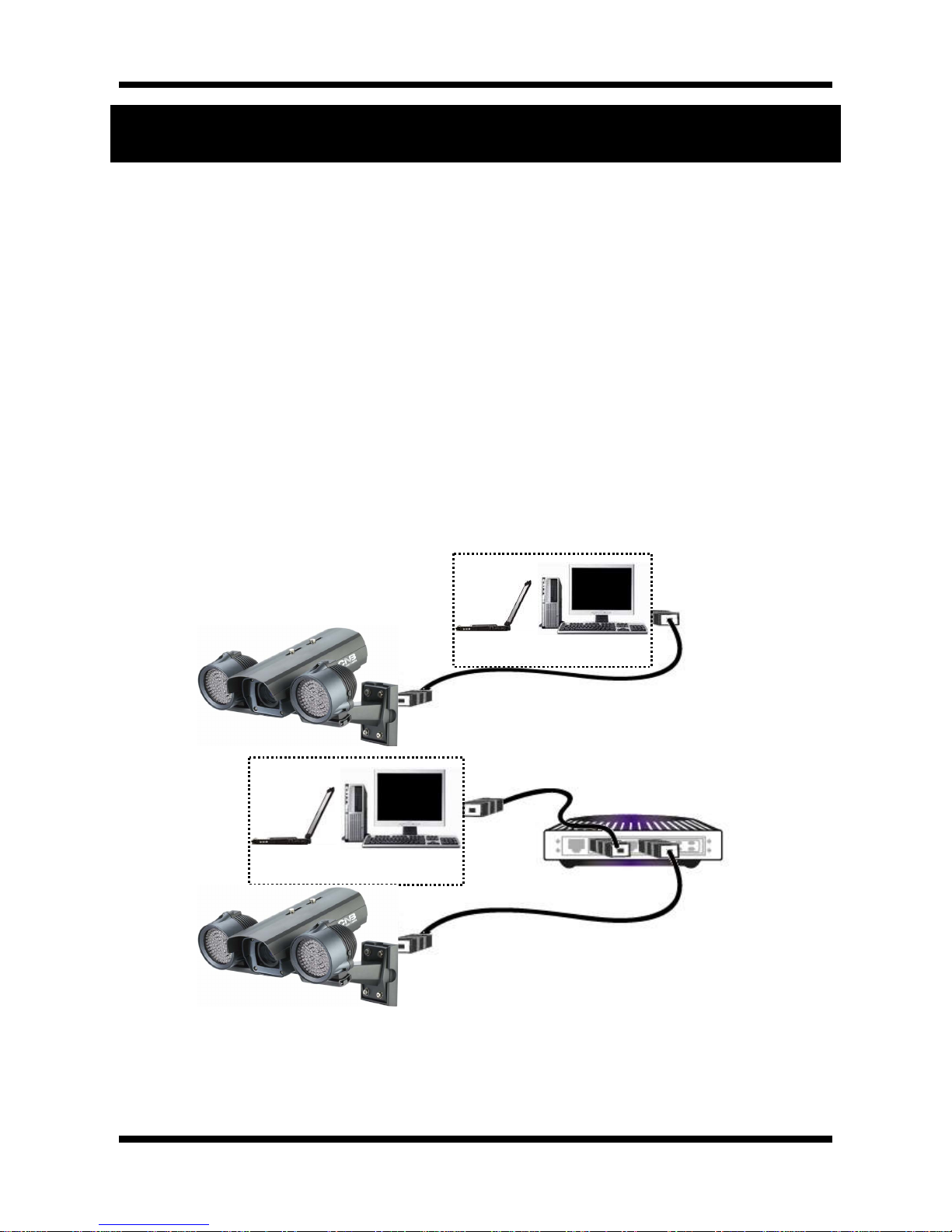
3.1. Connecting XNET to network
1. A PC or a laptop computer is required to configure an IP address.
zCompatible operating system: Windows 2000, Windows XP, and Windows Vista
zSince the default IP address of the device is 192.168.123.100, change the computer’s IP address to
192.168.123.101 and Subnet Mask to 255.255.255.0
2. Connect a monitor to VIDEO OUT terminal. (Select Video Out at Menu screen to enable analog video
output.)
3. Connect the computer or a network HUB to the product’s network input. (Use a crossover cable when
connecting it directly to a PC, and use a direct cable when connecting it to a HUB)
4. Connect the camera to a power source.
5. Connect Alarm Input/ output and audio if necessary.
Crossover Network Cable
COMPUTER
Direct Network Cable
COMPUTER
NETWORK HUB

Network Weatherproof Camera Installation Manual
13 / 20
3.2. Installing IP-Installer Software and Configuring IP address
3.2.1. About IP-Installer
A unique IP address is required in order to connect the network camera to the network and have a Client PC
connected to the camera remotely through the network. IP-Installer software, provided in the Installation CD
and also available to download from http://www.cnbtec.com, makes it easy to configure the IP address. If
your network uses DHCP server, the IP address will automatically be given by the network. If the network
does not have DHCP server, the default IP address is 192.168.123.100. For more details on how to install
and use IP Installer software, please refer to [Owner’s Manual for IP-Installer].
3.2.2. IP Address Configuration
1. The following window will pop up when you start the IP-installer software.
Figure 3-1. IP Installer Window

Network Weatherproof Camera Installation Manual
14 / 20
2. Select the camera you wish to configure and click (Set IP Address) button to open the box shown
in Figure 3-2.
Figure 3-2. Set IP Address box
3. When you enter the IP address and click Set button, the box shown in Figure 3-3 will appear.
Figure 3-3. Select Network Adapter Box
4. Select the adapter and click select button to change the IP address of the camera.

Network Weatherproof Camera Installation Manual
15 / 20
4. Using Web Viewer
You can connect to the network camera using a web browser or “XNET-CMS” software. For instructions on
how to use XNET-CMS software, please refer to XNET-CMS Manual, provided in the installation CD.
4.1. Logging In
On your web browser, enter the IP address of the camera on the address bar and press enter key.
Then the following box will appear:
Figure 4-1. Log-in Box

Network Weatherproof Camera Installation Manual
16 / 20
Enter the user name and password to bring up the web viewer page. The default id and password is
“root” and “admin” respectively.
If you changed the HTTP port number from the default value, put a colon and port number at the end of
the IP address. (For example, enter http://192.168.123.100:8080 when using port 8080.)
<Address format for accessing as an administrator>
(When using default IP address and port number)
http://192.168.123.100
(When using a different IP address and port number)
http://IP address: new port number
If you forget the administrator’s password, “Factory Reset” is the only way to regain access.
However, since this will retrieve all default settings, the network settings have to be
configured again using the IP installer.
For security, please change the administrator’s id and password from their default values. Please
save the changed ID and password in a place only accessible by an administrator. Please refer to
[Web Viewer Manual] for detail.

Network Weatherproof Camera Installation Manual
17 / 20
4.2. Web Viewer Page
Web viewer page consists of Video area and menu area.
Figure 4-2. Web Viewer page

Network Weatherproof Camera Installation Manual
18 / 20
Menu Sub
Menu Description
Capture - Captures and saves the current Video frame as a still image.
The image is saved as jpeg file in the following folder: C:₩xNetCapture
Setting - You can access the setup page for each XNET feature from this main setup page.
Please refer to [XNET Owner’s Manual] for detail.
PTZ -
This page can control digital PTZ of the camera, and it can also control the actual
PTZ movement.
Please refer to [XNET Owner’s Manual] for detail.
Motion - In this page, you can add /delete or set up the areas for motion detection.
Please refer to [XNET Owner’s Manual] for detail.
Multi
View -
In this page, you can view videos from other network cameras that are linked in
Multi Video Player setup page. Please refer to [XNET Owner’s Manual] for
detail.
Live
View
Main
Stream Check this box to display Main Stream video.
Sub
Stream
Check this box to display Sub Stream video.
Dual-Codec needs to be enabled in Video Setup Page in order to display the Sub
Stream Video.
Please refer to [XNET Owner’s Manual] for detail.

Network Weatherproof Camera Installation Manual
19 / 20
5. Specifications
IBP5030CR Specifications
Camera
Signal System Progressive image processing
Scanning System 4:3 Progressive
Pixel Clock 48 MHZ
Scanning Frequency (H) 26 KHz (NTSC) / 27 KHz (PAL)
Scanning Frequency (V) 24 KHz (NTSC) / 25 KHz (PAL)
Image Sensor 1/2" Progressive CMOS Sensor
Sync. System Internal
Effective Pixels Number 1280 (H) x 960 (V) 1.3 Mega pixel
Horizontal Resolution 800 TV Lines
Video Output Level Select NTSC/PAL 1.0Vp-p (BNC 75Ω, composite)
* VGA / QVGA Mode Only
Lens Built-in DC iris varifocal lens (f=7.5~50mm F1.3)
Back Light Compensation On/Off
Flickerless On/Off
White Balance Auto/Manual
Exposure Control Auto/Manual
Exposure Auto/Manual
Functions B/W
Electronic Shutter Speed NTSC : 1/6 ~ 1/600 (13 Step)
Min. Illumination 1 Lux (IR off / DSS on), 0 Lux (IR on)
IR LED and Sensor IR LED 206EA (850nm 15˚), Sensor 1EA
System Main Processors 32bit Embedded CPU with Linux
System Memory NAND Flash Memory : 64MByte, 128MB DDR Memory
Video / Audio
Compression SXGA / XGA : MJPEG
VGA : MJEPG / MPEG4 / H.264
Frame rate SXGA / XGA / VGA / CIF : 24 fps
Resolution SXGA (1280 x 960), XGA ( 1024 x 768), VGA (640 x 480), CIF (320 x 240)
Video streaming
SXGA / XGA : MJPEG Single mode, VGA : Dual Capable
Constant and variable bit rate in MPEG4 or H264
Controllable frame rate and bandwidth
Image settings Compression level setting
Configurable Brightness, Sharpness, White Balance
Network
Protocol Ipv4, HTTP, HTTPs, UDP, TCP, RTSP, RTP, SMTP, FTP, ICMP, DHCP, UPnP, Bonjour,
ARP, DNS, DynDNS, NTP, IGMP(Multicast) *) OnVif
Supported DDNS 1. CNB DDNS 2. DynDNS.org
3. Reference code with SDK
Video access from
Web browser Camera live view for up to 10 clients
LAN Interface Ethernet 10/100 Base-T (RJ-45 Type)
Security Access level setup Multiple user access levels with password protection
Network Security IP Filtering
Alarm and Event
Management
Image detection Motion detection (Select 3 Regions - each area)
Sensor detection Sensor In, Scheduling, Alarm out
After Event process JPEG Image upload over FTP server / SMTP (E-mail server)
Local storage JPEG Image write to Internal memory
- Internal memory : Max 32MByte
Pre / Post alarm Detail time-set : Max Pre alarm 5 sec / Post alarm 8 sec
Applications Browser Internet Explorer 6.0 or later

Network Weatherproof Camera Installation Manual
20 / 20
Monitoring Application
Web Viewer (Window Web Browser Base)
Live view for up to 10 user clients
Video Snapshot to file (JPEG)
XNET NVR, CNB CMS and Utility (IP-Installer, etc)
Maintenance
System Upgrade Firmware upgrade over HTTP
Digital Input / Output Control 1 Sensor / 1 Alarm, selectble with RS-485 by Cable
PTZ control (RS-485) PTZ Protocol Service (User define update), selectable with Digital I/O by Cable
Mechanical
Operating Temperature -10℃~ +50℃/ -20℃~ +50℃(with Fan & Heater)
Power DC 12V Max. 30 W(IR ON)
Dimensions / Weight (Net) 332.8(W) x 230.9(H) x 361.9(D)mm / Approx. 4kg
Dimensions(mm)
The casing, parts, and specifications of this product are subject to change without prior notice for
improvements.
Table of contents
Other CNB Security Camera manuals

CNB
CNB IXP3035VR User manual

CNB
CNB SKB-20Z12F User manual

CNB
CNB ALPHA 300 User manual

CNB
CNB AN200L Use and care manual

CNB
CNB ISS2000 Series User manual

CNB
CNB MPC1050IR User manual

CNB
CNB IDB4110NVF/IDB4110PVF/IVB4110NVF/IVB4110PVF User manual

CNB
CNB IGC2050F User manual

CNB
CNB XNET IVC5055VR User manual

CNB
CNB CNB-IGC2050F User manual


