Co-op ICE FISHING hut User manual

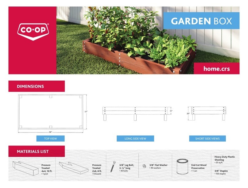
Pressure Treated
2x4, 8 ft.
• 3 boards
Spruce 2x4 , 8 ft.
•7 boards
DIMENSIONS
home.crs
MATERIALS LIST
3/8"
Plywood,
4' x 8'
• 8 sheets
Coated Deck Screws
• 1½" long, 396 screws (2.5 lbs.)
• 2½" long, 24 screws (0.2 lbs.)
• 3" long, 158 screws (1.75 lbs.)
Hurricane
Ties
• 6 ties
1½" Rigid
Insulation,
2' x 8'
• 1 sheet
4" Tee
Hinges
• 3 hinges
Spruce 2x2,
8 ft.
• 27 boards
#8 x 1" Wood Screws
• 60 screws
5½"
Door Pull
• 1 handle
FRONT VIEW SIDE VIEW
76" 48"
81
7
/
8"
23"
14
7
/
8"
95
5
/
8"
ICE FISHING hut

2
ICE FISHING HUT CONSTRUCTION
The Cutting Diagrams show how each piece of lumber is to
be broken down. Refer to the Detail Drawings for cutting
information regarding complex components. The components
are numbered in the order they are assembled.
2x4 Spruce Lumber
Seven (7) boards 8' long are required for the following components: #1, 2 ,3 18,
25 and 30.
2x4 Pressure-Treated Lumber
Three (3) boards 8' long are required for component #4.
CUTTING THE COMPONENTS
1
CUTTING DIAGRAMS
DETAIL DRAWINGS
96”
COMPONENTS LIST
# Component Name Quantity # Component Name Quantity
1 Joist Blocking 3 18 Header 1
2Floor Joist 4 19 Front Wall Bottom Plate 1
3Rim Joist 2 20 Front Wall Top Plate 1
4 Skid 3 21 Front Wall Sheathing (no window) 1
5Floor Sheathing 1 22 Front Wall Sheathing (window) 4
6 Bench Leg 4 23 Rear Wall Sheathing 2
7 Nailer 2 24 Side Wall Sheathing 2
8Rear Wall Stud 4 25 Rafter 2
9 Rear Wall Bottom Plate 1 26 Roof Sheathing 3
10 Rear Wall Top Plate 1 27 Header Sheathing 1
11 Side Wall Stud 6 28 Bench Seat Filler 2
12 Side Wall Bottom Plate 2 29 Bench Sheathing 4
13 Side Wall Top Plate 2 30 Bench Rail 2
14 Bench Cleat 231 Door Stile 2
15 Window Blocking 4 32 Door Rail 3
16 Front Wall Stud 4 33 Door Sheathing 1
17 Trimmer Stud 2 34 Window Retainer 4
320
11 28
724
15 32
421
12 29
825
16 33
17 34
219
10 27
623
14 31
118
926
522
13 30
76"
46
3
/
8" 47"
45
13
/
16"
76"
76" 1"
15°
71¼"
44¼"
21¾"
33"
15°
45°
1½"
46
3
/
8"
46
3
/
8"

3
2x2 Spruce Lumber
Twenty seven (27) boards 8' long are required
for the following components:
#6, 7, 8, 9, 10, 11, 12, 13, 14, 15, 16 ,17, 19, 20
28, 31 and 32.
CUTTING DIAGRAMS (continued)
71¼"
71¼"
71¼"
71¼"
44¼"
26¼"
44"
15°
15°
15°
15°
78"
44"
84¼"
10¾" 72"
14" 79½"
78
1
/
8"
72
3
/
8"
16
1
/
8"
83
7
/
8"
45
13
/
16"

4
3/8'' Plywood
Eight (8) 4' x 8' sheets are required for the following components:
#5, 21, 23, 24, 26, 27, 29, 33 and 34.
CUTTING DIAGRAMS (continued)
3/8" PLOOD
4' 8' sheets
47"
®
l
I 88�"
8
WINDOW RETAINER
(Optional)
r
2
!
3/8" PLOOD
4' 8' sheets
47"
®
l
I
88�"
8
WINDOW RETAINER
(Optional)
r
2
!
23¼"
16"
48"
53"
71"
71"
71"
71"
25
3
/
8"
43
7
/
8"23" 21½"
1½"
47"
20
3
/
8"
88
3
/
8"
26
5
/
8"
20
3
/
8"
3½"
3½"
2"
34

5
CUTTING DIAGRAMS (continued)
75¾"
75¾"
16¼"
16¼" 16¼"
29¾"
88
5
/
8"
88
5
/
8"83"
53"
44" 44"
48"
48"
44"
25
3
/
8"
22½"
4
1
/
8"
30
1
/
4"

3" Deck Screws -16
8¾"
8¾"
3" Deck Screws -12
NOTE:
The location of the blocking may
be adjusted to suit the desired ice
fishing hole size and location.
13
3
/
8"
13
3
/
8"
ICE FISHING HUT ASSEMBLY
2
•Connect the Joist Blocking (1) to the Floor Joists (2) using 3" Deck Screws. •Connect the Rim Joists (3) to the Floor Joists (2) using 3" Deck Screws.
NOTE:
• This Ice Fishing Hut is compact enough to fit in a 4' x 6½'
truck box with the tailgate closed. It can be constructed with
or without windows and insulation can be added to the walls,
floor, and ceiling as desired.
• lt is good practice to drill clearance and pilot holes before
installing wood screws in narrow boards. Doing so makes it
easier to align and assemble the joint, creates a stronger joint,
and reduces the chance of splitting the wood.
STEP 1. JOIST AND BLOCKING ASSEMBLY STEP 2. FLOOR FRAME ASSEMBLY
6

ICE FISHING HUT ASSEMBLY (continued)
•Connect the Skids (4) to the floor frame using Hurricane Ties and 1"
Wood Screws.
•Cut the holes and connect the Floor Sheathing (5) to the floor frame
using 1½" Deck Screws.
STEP 3.CONNECT THE SKIDS STEP 4. SHEATH THE FIOOR
7
Hurricane Ties - 6
1" Wood Screws - 60
Hurricane
Tie
1½" Deck Screws - 42
NOTE:
The Hurricane Ties are mounted on the
outside of the floor platform so the Skids
can be removed if they freeze into the ice.

ICE FISHING HUT ASSEMBLY (continued)
5.1 Connect the Bench Leg (6) to the Nailer (7) with 2½" Deck Screws to
form the Bench Leg Assembly.
5.2 Connect the Bench Leg Assemblies and the Rear Wall Studs (8) to the
Rear Wall Bottom Plate (9) and Rear Wall Top Plate (10) with 3" Deck
Screws. Note the orientation of the Bench Leg Assemblies.
6.1 After confirming the stud locations, connect the Side Wall Studs (11)
to the Side Wall Bottom Plate (12) and Side Wall Top Plate (13) with
3" Deck Screws.
6.2 Connect the Bench Cleat (14) to the studs as shown with 3" Deck Screws.
STEP 5. FRAME THE REAR WALL STEP 6. FRAME THE SIDE WALLS
8
2½" Deck Screws - 4
3" Deck Screws - 12
3" Deck Screws - 18
22½"
15
3
/
8"
15
3
/
8"
24
3
/
8"
24
3
/
8"
16
1
/
8"
22
1
/
8"
22
1
/
8"Note that the Bench
Cleats are placed on the
inside of each wall.
Bench Leg
Assembly

ICE FISHING HUT ASSEMBLY (continued)
8.1 Position the Header (18) on top of the Trimmer Studs (17) as shown and
secure with 3" Deck Screws.
8.2 Position the Front Wall Bottom Plate (19) and Front Wall Top Plate (20)
on the ends of the studs as shown.
8.3 Confirm the stud locations and secure the plates to the studs with
3" Deck Screws.
8.4 Position the Bench Legs (6) as shown and secure with 3" Deck Screws.
7.1 Position the Window Blocking (15) and Front Wall Studs (16) as shown
and connect with 3" Deck Screws.
7.2 Connect the Trimmer Studs (17) to the Front Wall Side Sections with
2½" Deck Screws.
STEP 7. FRAME THE FRONT WALL SIDE SECTIONS STEP 8. FRAME THE FRONT WALL
9
39¾"
25½"
19"
31½"
2½" Deck Screws - 12
3" Deck Screws - 8 3" Deck Screws - 12
19
7
/
8"
19
7
/
8"

ICE FISHING HUT ASSEMBLY (continued)
9.1 Secure the appropriate sheathing to the front wall with 1½"
Deck Screws.
9.2 Use Front Wall Sheathing (21) for walls with no windows and Front Wall
Sheathing (22) for walls with windows.
•Secure the Rear Wall Sheathing (23) to the rear wall framing with 1½"
Deck Screws.
STEP 9. SHEATH THE FRONT WALL STEP 10. SHEATH THE REAR WALL
10
1½" Deck Screws - 48 1½" Deck Screws - 48
NOTE:
• The shelter can be constructed with or without
windows. Select the appropriate sheathing.
• The Front Wall sheathing should sit 1/8" below
the top plate and 1/8" back of the studs.
• The sheathing should overhang the bottom
plate by 1
3
/
8".
• DO NOT install sheathing above the door at
this time.
NOTE:
• The Rear Wall sheathing should sit 1/8" below
the top plate and 1/8" back from the edge of
the studs.
• The sheathing should overhang the bottom
plate by 1
3
/
8".
• Be sure to drive screws through the sheathing
into the bench leg assemblies.
Sheathing sits 1/8" below
the top plate.
Sheathing will overhang
the rough opening on
all sides to support the
window panel.
Sheathing sits 1/8" back
from the stud edge. Sheathing 1/8" back
from stud edge.
1
3
/
8" Overhang
1
3
/
8" Overhang

ICE FISHING HUT ASSEMBLY (continued)
12.1 Stand the walls on the floor platform and secure with 3" Deck Screws
driven through the bottom plates into the floor joists.
12.2 Connect the corner studs with 3" Deck Screws driven through the front
and rear walls.
12.3 Drive 1½" Deck Screws through the sheathing overhangs into the floor
joists and studs.
•Secure the Side Wall Sheathing (24) to the side wall framing with
1½" Deck Screws.
STEP 11. SHEATH THE SIDE WALLS STEP 12. STAND THE WALLS
11
1½" Deck Screws - 72
1½" Deck Screws - 56
3" Deck Screws - 60
NOTE:
• The Side Wall sheathing should sit 1/8"
below the top plate.
• The sheathing should overhang the bottom
plate and studs by 1¾".
NOTE:
• A helper and/or adequate temporary bracing
is required to erect the walls safely.
1
3
/
8" Overhang
1
3
/
4"
Overhang
Sheathing 1/8" below top plate

ICE FISHING HUT ASSEMBLY (continued)
14.1 Beginning with the centre section, secure the Roof Sheathing (26)
with 1½" Deck Screws.
14.2 Install the Header Sheathing (27) above the door with 1½" Deck Screws.
13.1 Set the Rafters (25) between the Rear Wall Studs and the Front Top
Plate and Header.
13.2 Secure the rafters with 3" Deck Screws.
STEP 13. SET THE RAFTERS STEP 14. SHEATH THE ROOF
12
3" Deck Screws - 8
1½" Deck Screws - 54

ICE FISHING HUT ASSEMBLY (continued)
16.1 Position the Bench Rail (30) on the Bench Legs (6) as shown and
connect with 2½" Deck Screws.
16.2 Place the bench seat assembly on the Bench Rail and slide it back over
the Bench Cleat (14).
16.3 Secure the Bench Sheathing to the Cleat from the top and bottom with
1½" Deck Screws.
16.4 Secure the front edge of the bench seat assembly to the Bench Rail
with 3" Deck Screws.
15.1 Connect the Bench Seat Filler (28) to the Bench Sheathing (29) with
1½" Deck Screws.
15.2 Fill the space between the sheathing with Rigid Foam Insulation, leaving
a 1½" space on the back edge of the seat.
STEP 15. ASSEMBLE THE BENCH STEP 16. INSTALL THE BENCH SEATS
13
1½" Deck Screws - 20
1½" Rigid lnsulation - 2' x8' 1½" space to
accommodate the
Bench Cleat.
1½" Rigid Foam
Insulation
2½" Deck Screws - 8
1½" Deck Screws - 20
3" Deck Screws - 6
NOTE:
Walls have been removed from
the drawing to improve visibility
of critical components.

ICE FISHING HUT ASSEMBLY (continued)
18.1 Secure the hinges to the Trimmer Stud.
18.2 Working from the inside of the shelter, place the Window Panel in the
rough opening.
18.3 Secure the panel by attaching the Window Retainers (34) to the studs
and blocking around the rough opening with 1½" Deck Screws.
18.4 If desired, wall, joist and rafter cavities can now be filled with insulation.
17.1 Position the Door Stiles (31) and Door Rails (32) as shown and connect
with 3" Deck Screws.
17.2 Attach the Door Sheathing (33) to the door frame as indicated with
1½" Deck Screws.
17.3 Install theTee Hinge in line with the Door Rails.
17.4 lnstall the Door Handle as desired.
STEP 17. ASSEMBLE THE DOOR STEP 18. SET THE DOOR AND WINDOW
14
3" Deck Screws - 6
1½" Deck Screws - 28
4" Tee Hinges - 3
5½" Door Pull - 1
Sheathing
overhangs
the door
frame
by 1/4".
1½" Deck Screws - 8
In addition to the Terms of Use found at www.fcl.crs/contact-us/privacy-terms, you are responsible for any applicable code approval or permits associated with the construction and use of this plan.
Check with a building-code official or a building expert to make sure that the materials and construction methods shown meet local codes and conditions and are suitable to your situation. It is the
responsibility of the builder to ensure the proper tools, measurements, cuts and building techniques are used in the construction of this plan. CO-OP®assumes no responsibility for the incorrect use
of this information. Please ensure the manufacturer's instructions are followed in the use of all tools and materials and heed all recommended safety guidelines.
®CO-OP and design trademark are registered trademarks of Federated Co-operatives Limited, Saskatoon S7K 3M9
2¾"
4¾"
2¾"
2¾"
2"
36¼"
36¼"
36¼"
36¼"
NOTE:
• The window panel was not included in the materials
list at the start of these assembly instructions.
• A variety of materials can be used for this optional
component, including clear acrylic or polycarbonate
panels.
• A detail drawing of the window assembly, including
dimensions, is shown below.
Optional
Window Assembly
23⁄"
16"
Table of contents
Other Co-op Outdoor Furnishing manuals