Coantec C68 Series User manual
Industrial Videoscope
User Manual
COANTEC C68 Series
Please read the User Manuals carefully before using this instrument.

Copyright Statement
The User Manuals are applicable to Coantec C68 series videoscope. The copyright
is the property of Coantec Ltd. The contents of the User Manuals are protected by
Chinese laws and regulations pertaining to copyright. Without the written permission of
Coantec, the duplication, copy or translation of the User Manuals or any data and
information contained, or circulation of the User Manuals in any form will not be
allowed. Anyone who violates this will be held legally liable for relevant consequences.
Notice:
The Company is committed to continuously improving product functionality and
service quality and it reserves the right to change any product and software program
described in the User Manuals and the contents of the User Manuals without prior notice.
We have rigorously proofread and repeatedly reviewed the User Manuals. Even so, we
may not guarantee that all errors and omissions are eliminated. The User Manuals only
serve as a guidance to help the user use the Coantec instrument properly. However, it
does not represent any description of the software and hardware configuration of this
product.
In case of any questions, please call our after-sales service personnel. Tel.: +86
-755-89728626

1
Contents
1. User Notices.............................................................................................2
1.1 Purpose and Application Scope .....................................................2
1.2 Repair and Refitting.......................................................................2
1.3 Safety Precautions..........................................................................2
2. Products Description................................................................................4
3. Operation Process ....................................................................................5
4. User Manuals...........................................................................................6
4.1 Buttons and Interfaces ...................................................................6
4.2 Operation Interface ........................................................................9
4.3 User Management........................................................................13
4.4 Movement Control.......................................................................14
4.5 Speed Control ..............................................................................16
4.6 Illuminance Control .....................................................................17
4.7 Image Quality Adjustment ...........................................................18
4.8 Photo/Video .................................................................................19
4.9 Image Comparison.......................................................................21
4.10 File Preview ...............................................................................21
4.11 Picture Editing ...........................................................................24
4.12 Report Generation......................................................................25
4.13 File Reading...............................................................................26
4.14 Video Output..............................................................................27
5. 3D Measurement....................................................................................27
5.1 Measurement Interface.................................................................27
5.2 Measurement Steps......................................................................30
6. Cable Assembly and Disassembly .........................................................39
7. Basic Configuration ...............................................................................41
8. Storage and Maintenance.......................................................................41
9. Analysis and Troubleshooting of Common Faults.................................43

2
1. User Notices
1.1 Purpose and Application Scope
This product is only applicable to real-time industrial examination and
analysis. It can directly check the inner surfaces of pipes, turbines, cylinders,
engines and other devices for defects and abnormalities. This product is
characterized by direct viewing and supports real-time photo taking and video
recording, enabling the user to collect relevant data.
1.2 Repair and Refitting
This product has no parts or components that can be repaired by the user.
Do not try to disassemble, refit or repair the instrument by yourself, and Coantec
will not assume any responsibility for injury or loss caused to the user thereby.
This product can only be repaired by Coantec and its authorized dealers.
1.3 Safety Precautions
• When using this product, please observe the following instructions
to avoid accidental injury or instrument damage due to improper
operations:
① Do not use this instrument to check human or animal bodies.

3
② Do not work on the object under test while it is electrified in order to avoid
electric shock.
③ Do not touch the lens end with a bare hand during operation; otherwise, it
may cause burns.
④ Do not look directly at the strong light from the front end of the probe at
close range as it may affect your vision.
⑤ Do not bend, stretch, twist or roll over the tube excessively.
⑥ The image will be blurred if the lens is stained. Please wipe the lens clean
with a lint-free wiper dipped in a little alcohol before using the instrument.
⑦ Keep the insertion tube away from liquids other than water, saline, engine oil
and light oil.
⑧ Please clean the instrument in time after use.
⑨ Make sure that the insertion tube is straightened before turning on the
instrument. Do not make turns when the insertion tube is curled up. During
operation, toggle the joystick slowly to control the probe orientation and do not
keep the probe at the maximum bending angle for a long time; otherwise, its
service life will be affected.

4
⑩ If the instrument does not function properly, please stop examination
immediately and adjust the probe to the middle position, carefully retract the
insertion tube and turn off the instrument. Contact the manufacturer or
distributor in time.
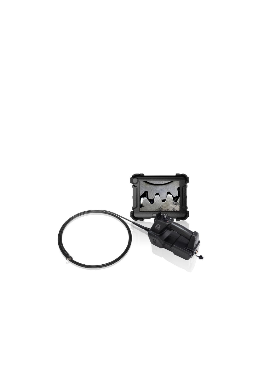
2. Products Description
The Coantec C68 series high-performance industrial videoscope is a new
visual inspection instrument independently developed by Coantec for
non-destructive testing. It features a high-quality image sensor, an IPS
wide-view HD LCD touch panel and advanced image processing technology,
delivering high-quality images of accurate color and more details. The
combination of the electric joystick and the virtual joystick on the touch panel
provides users with better manipulability, flexibility, and comfort. This
instrument enables users to see into areas that are impossible to examine with
the naked eye, offering a better guarantee for product quality and equipment
operation safety. It is applicable to the sectors of aviation, aerospace, energy,
electric power, chemicals, machinery, automobile, military, and special
equipment inspection.

5
3. Operation Process
① Unpacking of instrument: Open the instrument case and take out the host,
handle and umbilical cable. Please hold the probe properly during unpacking
and do not bump it. Connect the umbilical cable to the host and handle
according to the instructions.
② Preparation before turning on: Check whether all parts of the instrument are
in good condition, confirm that the battery and USB flash disk have been
correctly installed, and long press the power button to turn on the instrument.
③ Real-time examination: Extend the tube into the equipment or device to be
examined, and control the moving direction of the front-end probe by operating
the joystick.
④ Brightness adjustment: Adjust the brightness of the light source to obtain
appropriate illuminance and the clearest image possible.
⑤ Examination: Adjust the parameters such as the observation angle,
movement mode and speed of the probe as needed to examine the target in real
time, and carry out operations such as photographing, video recording, browsing
files and graffiti.
⑥ Tube retraction: Adjust the probe movement mode to the release to unlock
the probe for automatic resetting. Retract the tube slowly after it is
approximately straight.

6
⑦ Storage of instrument: Turn off the power switch, unplug the umbilical
cable, sort out and store all parts of the instrument into the case, close the upper
cover and fasten the lock catch.
4. User Manuals
4.1 Buttons and Interfaces
The functional buttons and interfaces of the C68 series industrial
videoscope are shown in Fig. 1 and Fig. 1-1, and the functional buttons and
interfaces for handle operation are shown in Fig. 1-2:
Fig. 1

7
Fig. 1-1
Electric Joystick Mechanical Joystick
Fig. 1-2

8
① Power/return/display or hide main menu button: Long press the button to
turn on/off the instrument; press the button briefly to display/hide the main
menu, or return to the parent menu.
② Menu selection button: Rotate the button to switch among the menus,
and press the button to select the current menu.
③ HDMI interface: The high-definition multimedia interface is used to
connect an external display to output video images.
④ VGA interface (optional): It is an analog signal output interface to
connect an external display for video image output.
⑤ USB3.0 interface: It is used to connect USB flash disk for image data
storage.
⑥ USB3.0 interface: It is used to connect USB flash disk for image data
storage.
⑦ HP interface: It is used to connect the headset for audio signal output.
⑧ Cable interface (host end): It is for the cable connecting the operating
handle to the host.
⑨ Bracket: It is used to adjust the sitting angle of the host.
⑩ Charging interface: It is used to connect an adapter for online charging of the
instrument.

9
⑪ Knurled screw: The cover of battery compartment can be open or closed by
adjusting the screw.
⑫ Battery compartment: It holds the battery module. Loosen/tighten the
knurled screw to open/close the rear cover of the battery compartment.
⑬ Cable interface (handle end): It is for the cable connecting the operating
handle to the host.
⑭ Joystick: It controls the movement direction and angle of the probe. Press the
button in the middle to switch the probe to the release/lock mode.
⑮ OFF button: Long press the button to turn off the instrument directly.
⑯ Zoom button: It is used to zoom in or out the real-time inspection image.
⑰ LED brightness adjustment button: It is used to adjust the LED illuminance.
⑱ Indicator: When the probe is unlocked and in tracking mode, the indicator
will light up in green; when the probe is locked and in steeping mode, the
indicator will light up in red.
⑲ Photo/video button: It is used to take photos and record videos under
photo/video mode.
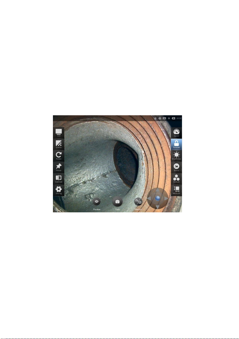
4.2 Operation Interface
Long press the power button for about 3 seconds to turn on the host, and
the indicator at the upper left of the operating handle will light up in green. The
system boots up and the startup picture shows on the display. After the program

10
is loaded, the home interface of real-time examination will show on the display
(as shown in Fig. 2). Extend the insertion tube into the target to be examined to
start the examination.
Note: Before the examination, the insertion tube shall be straightened. Do
not make turns when the insertion tube is curled up.
Press the power button briefly or double-click the blank area on the screen
to enable the menu function setting (press the button briefly again to hide the
menu). Rotate the menu selection button to switch over among the menus
available and press the button to confirm the selection.
The buttons in the main menu correspond to the functions described below
(as shown in Fig. 2):

11
Fig. 2
① Image resolution: The video resolution can be set to 640*360, 640*480 and
1280*720. (Note: The resolution options may vary depending on the tube size.)
② Image quality: This button is used to adjust the brightness, contrast, tone,
saturation, definition, gamma of the image and reset the image quality to
default.
③ Rotation: Click this button to rotate the real-time examination image
clockwise by 90° every time.
④ Freezing: Click the button to freeze the real-time examination image.

12
⑤ Comparison: Click this button to compare the real-time examination image
with the image saved.
⑥ Settings: Click this button to enter the setting interface where the following
operations can be performed:
⚫ WLAN: Enable the WLAN and enter the password to access the WLAN
available.
⚫ User management: Set the instrument to administrator, visitor, standard
user (set by administrator) mode.
⚫ About the instrument: Check the instrument information, check for
upgrade available, and upgrade the instrument to the latest version.
⚫ Display: Adjust the brightness (by automatic sensing or manual setting).
Enable or disable the virtual joystick, the watermark (of time and location)
and the rulers (none, cross ruler, circular ruler or reference line). Set the
language (simplified Chinese and English), date and time.
⚫ Help document: It provides product instructions.
⑦ Speed: Adjust the moving speed of the probe. There are two options, fast and
low.
⑧ Release: Lock/release the probe.
⑨ Illuminance: Set the illuminance of the probe LED. It is adjustable from
level 0 to level 9.

13
⑩ Scenario: Provide the attribute of the target to be examined, metal or
non-metal.
⑪ Image: Set the image quality to default, monochrome, negative, bright,
highlighted, or soft.
⑫ Measurement: Enter 3D measurement mode (applicable to binocular camera
only).
⑬ Preview: Enter the file browsing interface.
⑭ Photo taking: Take photos and save them automatically.
⑮ Switching: Switch between photo/video modes.
⑯ Virtual joystick: Drag the blue roller in the middle of the virtual joystick to
turn the probe orientation.
⑰ Icon display: The icons in the upper right corner of the screen indicate the
current status: probe locked (no icon if the probe is released), probe moving
speed (fast/slow), image magnification (1~5 times), LED illuminance level
(0~9), battery power and system time.
4.3 User Management
The user management is mainly used to provide permissions for functions
such as photographing, video recording and report generation (as shown in Fig.
3). Enter the user management interface from the setting function on the home
interface(as shown in .Fig. 3-1). Log in as an administrator (the initial password

14
is "123456"), and then the user may create a standard user, delete a user, and
change the password. Information such as images taken and reports generated in
different user management modes can only be viewed and processed in the
current mode. The default mode is visitor mode, requiring no login.
Fig. 3

15
Fig. 3-1
4.4 Movement Control
In the real-time examination mode, the direction and angle of probe
movement can be controlled by toggling the joystick or using the virtual joystick,
and the probe movement mode can be switched by pressing the lock/release
button or the middle button of the joystick in the main menu interface (as shown
in Fig. 4).
Release: The probe bends towards the joystick moving direction. Release
the joystick, and the probe will automatically reset. Under this mode, the user
may identify the target to be examined quickly;
Locking: Toggle the joystick and the probe will inch. This ensures accurate
control of the probe moving angle, thus facilitating precise observation of the
16
target to be examined. The middle button of the joystick can release the locked
probe (automatic reset).
Virtual joystick: Set to display the virtual joystick on the main menu to
enable relevant functions. Drag the blue roller in the middle of the virtual
joystick to turn the probe and differentiate release/lock mode.
Fig. 4
4.5 Speed Control
In the real-time examination mode, the moving speed of the probe can be
controlled by the speed control button(as shown in .Fig. 5). The current moving
mode is displayed in the upper right corner of the screen.

17
Fig. 5
4.6 Illuminance Control
In the real-time examination mode, the illuminance of the front-end probe
LED can be controlled by the illuminance adjustment button (as shown in Fig. 6
and Fig. 6-1) to obtain a better observation view. The illuminance is adjustable
from Level 0 to Level 9. At Level 0, the LED is off, while at Level 9, the highest
illuminance will be given. The current illuminance level is displayed in the
upper right corner of the screen.
18
Fig. 6
Fig. 6-1
4.7 Image Quality Adjustment
Enter the image quality adjustment interface from the home interface. The
user may adjust the following parameters of the image or restore the default
settings (as shown in Fig.7) according to the actual situation. The parameters are
adjustable within the following ranges:
Image brightness: -64~64
Contrast: 0~64
Tone: -40~-40
Table of contents
Other Coantec Diagnostic Equipment manuals


