Midtronics Inc. 7000 Monroe Street Willowbrook, IL 60527
www.midtronics.com
Midtronics Inc. 7000 Monroe Street Willowbrook, IL 60527 www.midtronics.com
67
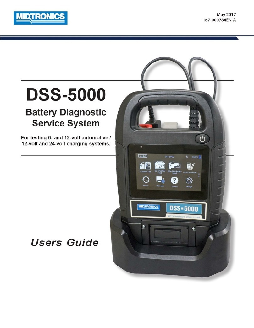
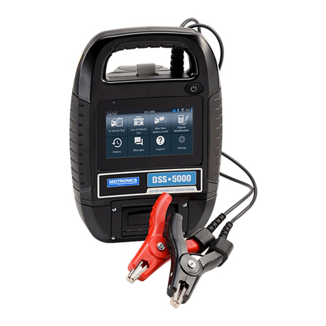
Chapter 1: Introduction Chapter 1: IntroductionDSS-5000 DSS-5000
Test Preparation
Inspecting the Battery
Before starting the test, visually inspect the battery for:
•Cracked, buckled, or leaking case: If you see any of these
defects, replace the battery.
•Corroded, loose, or damaged cables and connections.
Repair or replace them as needed.
•Corrosion on the battery terminals, and dirt or acid on the
case top: clean the case and terminals using a wire brush
and a mixture of water and baking soda.
•Low electrolyte level. If the electrolyte level is too low, add
distilled water to ll up to ½ of the space above the top
of the plates and fully charge the battery. Do not overll.
•Corroded or loose battery tray and hold-down xture:
Tighten or replace as needed.
Testing Out-of-Vehicle
The preferred battery test location is in the vehicle. However, if
you plan to test out of the vehicle:
•Always disconnect the negative cable from the battery
rst and reconnect it last.
•Always use a carry tool or strap to lift and transport the
battery.
Failure to properly install lead terminal adapters,
or using adapters that are dirty or worn, may
cause false test results.
When testing side-post or Group 31 batteries, always use lead
terminal adapters provided with the tester—do not test at
the battery’s steel bolts. To avoid damage, never use a wrench
to tighten the adapters more than ¼ turn.
Testing In-Vehicle
The preferred test position is at the battery posts. If you must
test at a remote-post location, it should have both a positive
and negative post. Otherwise, you must remove the battery
and perform an out-of-vehicle test.
At the start of the test, make sure all vehicle accessory loads
are o, the key is not in the ignition, and the doors are closed.
Connecting To A Battery
Do not connect the tester to a voltage source
greater than 30 Vdc.
Connect the clamps to the tester: the red clamp to the positive
(+) terminal and the black clamp to the negative (–) terminal.
If you connect the clamps in the wrong polarity (positive to
negative or negative to positive), the tester displays CLAMPS
REVERSED! Reconnect the clamps properly.
To make sure both sides of the clamps are gripping the
terminals, rock the each clamp back and forth. A poor
connection will prevent testing, and the tester will display
the message CHECK CONNECTION. If the message reappears
after you have correctly reconnected the clamps, clean the
terminals and reconnect.
Setting User Preferences
Before starting your test you may want to customize the use of
your tester by setting preferences in the Settings ( ) Menu.
The Settings Menu is described in Chapter 9.
Initial Power Up
1. Upon initial power-up, the Language Settings screen is
displayed. Tap Next to continue.
System
Language
Select the Controller default language
displayed on the screen.
Test Result
Language
Select the Controller default language
for all displayed tests and test results.
Email
Language
Select the default standard language for
the tester to use for all tests and results
sent via email.
Print
Language
Select the default standard language for
the tester to use for all tests and results
printed using a networked printer.
2. A Consent to collect data screen is displayed. Tap the Con-
sent check box and then tap Next to continue.
3. Using the displayed keypad template, enter the new user
name and password.
4. Tap Next to continue.
IMPORTANT: By default, the rst user created is
assigned Administrator rights. Tap Add User to
add additional users. See Chapter 9: Settings to
change these defaults.
Tester Components
Controller
Carrying Handle: For carrying the Controller and Tester
Pod (when attached).
Controller Release Lever: Pull to release the Controller
from the Tester Pod.
Power Button: Hold for 2 seconds to
turn the Controller
on and o independent of the Tester Pod. Flashes when
the Controller is being charged.
Touch Screen: Primary user interface.
Camera & Flashlight: For VIN scanning and identication.
Temperature Sensor: For measuring battery temperature.
Micro-USB Port: For updating and servicing the Control-
ler when a WiFi network is not available.
Power Supply Connection
Tester Pod
Controller Charging Contacts: For charging and communi-
cating
with the Controller when mounted to the Tester Pod.
Status Indicator LEDs:
- Power is on - Clamps reversed
- Tester Pod is communicating with the Controller
Clamp Storage Mounts: Use to keep the test clamps
protected when the tester is not in use.
Tester Pod Internal Batteries
Charging Dock
Tester Pod Charging Contacts: For charging the Tester Pod
Power Supply Connection


