Coartal EOS Veranda on Ceiling User manual

Manual Instalación
Veranda EOS Sobre Techo
Assembly Instructions for EOS Veranda on Ceiling
Manuel Installation Veranda EOS Sur Toit
Manuale di Installazione Veranda EOS a Tetto
Veranda EOS Sobre-Techo CERRADO
CLOSED EOS Veranda on Ceiling
Veranda EOS Sur-Toit FERMÉ
Veranda EOS su Tetto CHIUSO
Veranda EOS Sobre-Techo ABIERTO
OPENED EOS Veranda on Ceiling
Veranda EOS Sur-Toit OUVERT
Veranda EOS su Tetto APERTO
www.coartal.com

CÓDIGO / CODE / CODICE
DESCRIPCIÓN DEL ARTÍCULO / ARTICLE DESCRIPTION / DESCRIPTION ARTICLE / DESCRIZIONE
80110065
J. PERFILES COFRE EOS BLANCO 4M / SET OF PROFILES FOR EOS BOX, WHITE 4M
J. PROFILS COFFRE EOS BLANC 4M / SET PROFILI CASSONETTO EOS L=4M BIANCO
80110066
J. PERFILES COFRE EOS RAL ESP. 4M / SET OF PROFILES FOR EOS BOX, SPECIAL RAL 4M
J. PROFILS COFFRE EOS RAL SPÉCIAL 4M / SET PROFILI CASSONETTO EOS L=4M RAL SPECIALE
80110002
J. PERFILES COFRE EOS BLANCO 5M / SET OF PROFILES FOR EOS BOX, WHITE 5M
J. PROFILS COFFRE EOS BLANC 5M / SET PROFILI CASSONETTO EOS L=5M BIANCO
80110007
J. PERFILES COFRE EOS RAL ESP. 5M / SET OF PROFILES FOR EOS BOX, SPECIAL RAL 5M
J. PROFILS COFFRE EOS RAL SPÉCIAL 5M/ SET PROFILI CASSONETTO EOS L=5M RAL SPECIALE
80110051
J. PERFILES COFRE EOS BLANCO 6M / SET OF PROFILES FOR EOS BOX, WHITE 6M
J. PROFILS COFFRE EOS BLANC 6M / SET PROFILI CASSONETTO EOS L=6M BIANCO
80110056
J. PERFILES COFRE EOS RAL ESP. 6M / SET OF PROFILES FOR EOS BOX, SPECIAL RAL 6M
J. PROFILS COFFRE EOS RAL SPÉCIAL 6M / SET PROFILI CASSONETTO EOS L=6M RAL SPECIALE
80110068
J. PERFILES COFRE EOS BLANCO 7M / SET OF PROFILES FOR EOS BOX, WHITE 7M
J. PROFILS COFFRE EOS BLANC 7M / SET PROFILI CASSONETTO EOS L=7M BIANCO
80110069
J. PERFILES COFRE EOS RAL ESP. 7M / SET OF PROFILES FOR EOS BOX, SPECIAL RAL 7M
J. PROFILS COFFRE EOS RAL SPÉCIAL 7M / SET PROFILI CASSONETTO EOS L=7M RAL SPECIALE
80110099
PERFIL BARRA CARGA EOS BLANCO 4M / EOS CHARGE PROFILE, WHITE 4M
PROFIL BARRE DE CHARGE EOS BLANC 4 M / PROFILO TERMINALE EOS L=4M BIANCO
80110100
PERFIL BARRA CARGA EOS RAL ESP. 4M / EOS CHARGE PROFILE, SPECIAL RAL 4M
PROFIL BARRE DE CHARGE EOS 4M RAL SPÉCIAL / PROFILO TERMINALE EOS L=4M RAL SPECIALE
80110085
PERFIL BARRA CARGA EOS BLANCO 5M / EOS CHARGE PROFILE, WHITE 5M
PROFIL BARRE DE CHARGE EOS BLANC 5 M / PROFILO TERMINALE EOS L=5M BIANCO
80110090
PERFIL BARRA CARGA EOS RAL ESP. 5M / EOS CHARGE PROFILE, SPECIAL RAL 5M
PROFIL BARRE DE CHARGE EOS 5 M RAL SPÉCIAL / PROFILO TERMINALE EOS L=5M RAL SPECIALE
80110092
PERFIL BARRA CARGA EOS BLANCO 6M / EOS CHARGE PROFILE, WHITE 6M
PROFIL BARRE DE CHARGE EOS BLANC 6M / PROFILO TERMINALE EOS L=6M BIANCO
80110097
PERFIL BARRA CARGA EOS RAL ESP. 6M / EOS CHARGE PROFILE, SPECIAL RAL 6M
PROFIL BARRE DE CHARGE EOS 6M RAL SPÉCIAL / PROFILO TERMINALE EOS L=6M RAL SPECIALE
80110102
PERFIL BARRA CARGA EOS BLANCO 7M / EOS CHARGE PROFILE, WHITE 7M
PROFIL BARRE DE CHARGE EOS BLANC 7M / PROFILO TERMINALE EOS L=7M BIANCO
80110103
PERFIL BARRA CARGA EOS RAL ESP. 7M / EOS CHARGE PROFILE, SPECIAL RAL 7M
PROFIL BARRE DE CHARGE EOS 7M RAL SPÉCIAL / PROFILO TERMINALE EOS L=7M RAL SPECIALE
80110009
KIT ANCLAJE EOS S/TECHO BLANCO / SET OF FIXING SUPPORTS FOR EOS, WHITE
KIT FIXATION S/TOIT BLANC / KIT SUPPORTO VERANDA EOS SU TETTO BIANCO
80110014
KIT ANCLAJE EOS S/TECHORALESP. / SET OF FIXING SUPPORTS FOR EOS, SPECIAL RAL
KIT FIXATION S/TOIT RAL SPÉCIAL / KIT SUPPORTO VERANDA EOS SU TETTO RAL SPECIALE
80110044
KIT TAPAS COFRE EOS BLANCO / SET OF CAPS FOR EOS BOX, WHITE
KIT EMBOUTS COFFRE EOS BLANC / KIT TAPPI CASSONETTO EOS BIANCO
80110049
KIT TAPAS COFRE EOS RAL ESP. / SET OF CAPS FOR EOS BOX, SPECIAL RAL
KIT EMBOUTS COFFRE EOS RAL SPÉCIAL / KIT TAPPI CASSONETTO EOS RAL SPECIALE
80110128
J. TAPAS EMPALME CAJÓN EOS BLANCO / SET OF JOINT CAPS FOR EOS BOX, WHITE
J. EMBOUTS D’ABOUTAGE CAISSON EOS BLANC / SET TAPPI GIUNZIONE CASSONETTO EOS BIANCO
80110129
J. TAPAS EMPALME CAJÓN EOS RAL ESP. / SET OF JOINT CAPS FOR EOS BOX, SPECIAL RAL
J. EMBOUTS D’ABOUTAGE CAISSON EOS RAL SPÉCIAL / SET TAPPI GIUNZIONE CASSONETTO EOS RAL SPECIALE
80110120
J. GUÍAS EOS BLANCO 2.5M / SET OF GUIDES FOR EOS, WHITE 2,5M
J. PROFILS DE GUIDAJE BLANC 2.5M / COPPIE GUIDE EOS BIANCO L= 2,5M
80110125
J. GUÍAS EOS RAL ESP. 2.5M / SET OF GUIDES FOR EOS, SPECIAL RAL 2,5M
J. PROFILS DE GUIDAJE RAL SPÉCIAL 2.5M / COPPIE GUIDE EOS RAL SPECIALE L=2,5M
80110016
J. GUÍAS EOS BLANCO 3M / SET OF GUIDES FOR EOS, WHITE 3M
J. PROFILS DE GUIDAJE BLANC 3M / COPPIE GUIDE EOS BIANCO L=3M
80110021
J. GUÍAS EOS RAL ESP. 3M / SET OF GUIDES FOR EOS, SPECIAL RAL 3M
J. PROFILS DE GUIDAJE RAL SPÉCIAL 3M / COPPIE GUIDE EOS RAL SPECIALE L=3M
80110023
J. GUÍAS EOS BLANCO 4M / SET OF GUIDES FOR EOS, WHITE 4M
J. PROFILS DE GUIDAJE BLANC 4M / COPPIE GUIDE EOS BIANCO L=4M
80110028
J. GUÍAS EOS RAL ESP. 4M / SET OF GUIDES FOR EOS, SPECIAL RAL 4M
J. PROFILS DE GUIDAJE RAL SPÉCIAL 4M / COPPIE GUIDE EOS RAL SPECIALE L=4M
80110030
J. GUÍAS EOS BLANCO 5M / SET OF GUIDES FOR EOS, WHITE 5M
J. PROFILS DE GUIDAJE BLANC 5M / COPPIE GUIDE EOS BIANCO L=5 M
80110035
J. GUÍAS EOS RAL ESP. 5M / SET OF GUIDES FOR EOS, SPECIAL RAL 5M
J. PROFILS DE GUIDAJE RAL SPÉCIAL 5M / COPPIE GUIDE EOS RAL SPECIALE L=5M
80110037
J. GUÍAS EOS BLANCO 6M / SET OF GUIDES FOR EOS, WHITE 6M
J. PROFILS DE GUIDAJE BLANC 6M / COPPIE GUIDE EOS BIANCO L=6M
80110042
J. GUÍAS EOS RAL ESP. 6M / SET OF GUIDES FOR EOS, SPECIAL RAL 6M
J. PROFILS DE GUIDAJE RAL SPÉCIAL 6M/ COPPIE GUIDE EOS RAL SPECIALE L=6M

RECOMENDACIONES DE USO:
RECOMMANDATIONS D’UTILISATION:
USE RECOMMENDATIONS:
RACCOMANDAZIONI D’USO:
Guías: 2,5 m / Guides: 2,5 m
Profil 2,5 m / Guide: 2,5 m
Guías: 3 m, 4 m / Guides: 3 m, 4m
Profil 3 m, 4 m / Guide: 3 m, 4 m
Guías: 5 m, 6 m / Guides: 5 m, 6m
Profil 5 m, 6 m / Guide: 5 m, 6 m
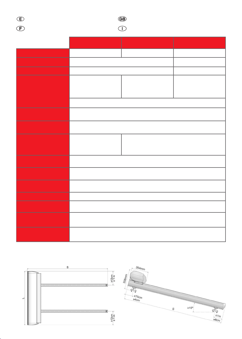
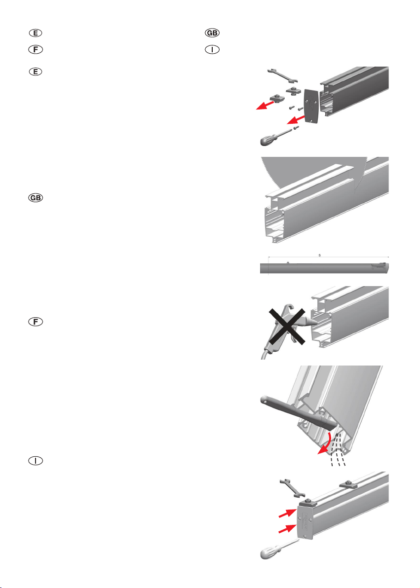
Longitud de corte de guía S /Cutting adjustments for theS guide
Longueur coupe profil de guidage S /Lunghezza di taglioguida S
Mínimo 1,6 m / 1,6 m minimum
Minimum 1,6 m / Minimo 1,6 m
Mínimo 2,5 m / 2,5 m minimum
Minimum 2,5 m / Minimo 2,5 m
Mínimo 4 m / 4 m minimum
Minimum 4 m / Minimo 4 m
Longitud cofre L /L box length
Longueur coffre L /Lunghezza cassonetto L
Máximo 6 m / 6 m maximum
Maximum 6 m / Massimo 6 m
Máximo 5 m / 5 m maximum
Maximum 5 m / Massimo 5 m
Pies / Supports / Pieds / Supporti inferiori
Mínimo 2 por guía / Minimum 2 per guide
Minimum 2 par profil de guidage / Minimo 2 per guida
Mínimo 3 por guía / Minimum 3 per guide
Minimum 3 par profil de guidage/Minimo 3 per guida
Motor* / Motor* / Moteur* / Motore*
Mínimo 50 N*m/ 50 N*m Minimum
Minimum 50 N*m/ Minimo 50 N*m
(1)
(GM-50 Cod: 60050006) (ARGOS 50 Cod: 60050105)
(1)
Si raccomanda minimo 80 N*m per l’Italia
(DAYTONA 80 Cod: 6C2.61250)
Mínimo 80 N*m/ 80 N*m Minimum
Minimum 80 N*m/ Minimo 80 N*m
(2)
(GM-80 Cod: 60050009)
(2)
Si raccomanda minimo 100 N*m per l’Italia
(DAYTONA 100 Cod: 6C2.61290)
Mínimo 120 N*m/ 120 N*m Minimum
Minimum 120 N*m/ Minimo 120 N*m (3)
(GM-120 Cod: 60050011)
(3)
Italia: (DAYTONA 120Nm
Cod: 6C2.61350)
Nota: se recomienda la utilización del motor tipo cofre como Somfy o similares / Note: it is recommended to use a motor for box like Somfy or similar
Note:onrecommande l´utilisation d´un moteur type coffre comme Somfy ou similaire/ Per motorielettronici si consiglia l’uso di motoriSomfy o similari
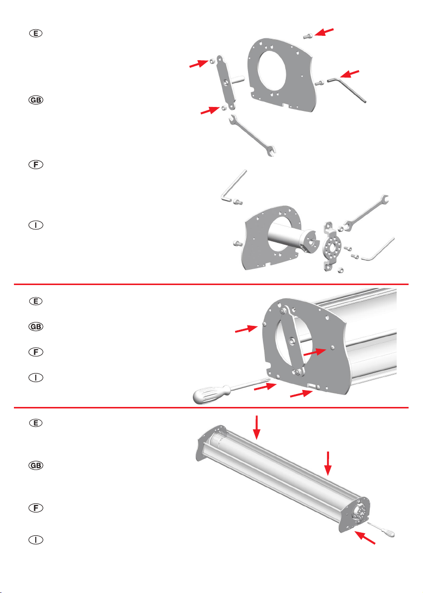
Eje / Tube / Axe / Rullo
Eje Ø 85x1.2 mm ojiva, rizado, longitudes 4 m, 5 m, 6 m, 7 m / Ø 85x1,2 mm tube with ogive, crinkle, 4 m, 5 m, 6 m, 7 m length
Axe Ø 85 x 1,2 mm à gorge, ondulé 4 m, 5 m, 6 m, 7 m / Rullo Ø 85x1.2 mm ogiva, con nervature, lunghezza 4 m, 5 m, 6 m, 7 m
(Cods: 80030052, 80030050, 80030051, 80030053-6B4.3585/L)
Casquillo / Round cap / Embout / Calotte
Casquillo Ø 85-ojiva, agujero Ø 14 mm / Round cap of Ø 85 ogive, with round hole Ø 14 mm
Embout Ø 85 à gorge, trou Ø 14 mm / Calotte Ø 85 ogiva, foro Ø 14 mm
(Cod: 80020086)
Adaptador Motor-Eje / Motor-Tube Adapter
Adapteur Moteur-Axe / Adattatore Motore - Rullo
Adaptador para eje ojiva Ø85 y motor serie 50
Adapter for Ø 85 ogive tube and 50 Series motors
Adapteur pour axe Ø85 à gorge et moteur sèrie 50
Adattatore per rullo ogiva Ø85 serie-50(4)
(Cods: 60070054, 6C4.6047/T)
(4)
Italia: Serie 60 (Cod: 6C4.60470)
Adaptador para eje Ø85-ojiva y motor serie 60
Adapter for Ø 85 ogive tube and 60 Series motors
Adapteur pour axe Ø85 à gorge et moteur serie 60
Adattatore per rullo ogiva Ø85 e motore serie 60
(Cods: 60070050, 6C4.60470)
Voladizo lateral / Lateral cantilever
Saillie latérale / Sporgenza laterale
Máximo 1 m - Mínimo 12 cm / 1 m maximum - 12 cm minimum / Maximum 1 m - Minimum 12 cm / Massimo 1 m – Minimo 12 cm
Se recomienda que sea el menor posible / It is recommended to use as small as possible
On recommande la moindre posible / Si raccomanda che sia il più piccolo possibile
Voladizo trasero / Rear cantilever
Saillie arrière / Sporgenza posteriore
Máximo 75 cm / 75 cm maximum / Maximum 75 cm / Massimo 75 cm
Se recomienda que sea el menor posible / It is recommended to use as small as possible
On recommande la moindre posible / Si raccomanda che sia il più piccolo possibile
Voladizo delantero / Frontal cantilever
Saillie avant / Sporgenza anteriore
Máximo 1 m / 1 m maximum / Maximum 1 m / Massimo 1 m
Se recomienda que sea el menor posible / It is recommended to use as small as possible
On recommande la moindre posible / Si raccomanda che sia il più piccolo possibile
Inclinación / Slope / Inclinaison / Inclinazione
Mínimo 15º / 15º minimum / Minimum 15º / Minimo 15º
Cosido de lona / Fabric sewing
Toile cousue / Tessuto cucito
Realizar refuerzos a la lona de 10 cm de ancho a 10 cm de los bordes / Make a 10 cm width reinforcement around 10 cm from the fabric b orders
Réaliser des renforts sur la toile de 10 cm de large à 10 cm des bords / Eseguire dei rinforzi sul tessuto di 10 cm di larghezza a 10 cm dai b ordi
Lona recomendada / Recommended fabric
Toile recommandée / Tessuto consigliato
Lona poliéster, resinada a una cara, peso máximo 400 gr/m², resistencia a la rotura mínima de 200 daN según ISO-13934-1 / Polyester fabric, with
resin on one side, 400 gr/m² maximum weight, minimum rupture strength of 200 daN according to ISO-13934-1 / Toile polyester, résinée sur une
face, poids maximum 400 gr/m² résistance á la déchirure mínimum de 200 daN selon norme ISO-13934-1 / Tessuto in poliestere, resinato da una
parte, peso massimo 400 gr/m², resistenza alla rotura minima di 200 daN secondo ISO-13934-1
Punto Rodamiento / Ball bearing round pivot
Point roulement à billes
Supporto foro tondo con cuscinetto
Se recomienda incluir el punto con rodamiento H=20 mm, para lo cual se utilizará el casquillo Ø85 espiga Ø12 mm
It is recommended to use the round pivot with H=20 mm ball bearing, thus, the Ø85 round cap with Ø12 mm pivot should be used
Point roulement à billes recommandé H=20 mm, avec embout mâle Ø85, sortie ronde Ø12mm
Supporto foro tondo con cuscinetto H=20 mm, per il quale si userà calotta Ø85 perno Ø12 mm
* El par mínimo es para instalaciones con 2 guías. Para instalaciones con 3 o más guías, aumentar proporcionalmente el par motor.
* The minimum torque is for installations with 2 guides. For installations with 3 or more guides, progressively increase the motor torque.
* Le couple moteur minimum indiqué pour installations avec 2 profiles de guidage. Pour installations avec 3 de profils de guidage ou plus, augmenter proportionellement le couple moteur.
* La coppia minima è per l’installazione con 2 guide. Per installazione con 3 o piu’ guide aumentare progressivamente la coppia minima (5)
.
(5)
Italia: Attenzione: non e’ possibile installare con 3 o piu’ guide.

MONTAJE EN FÁBRICA:
ASSEMBLAGE A L’USINE:
Paso 1: Ajustar la longitud de las guías:
• Desmontar la tapa trasera y las garras.
• Cortar la parte sobrante de la guía. Ver longitudes mínimas de
corte en la tabla de “Recomendaciones de Uso” al principio
del manual. Muy importante: las dos guías han de cortarse a
la misma longitud ±1mm.
• Retirar la viruta del interior del perl, volcándolo hacia abajo
y/o con un pincel; jamás con pistola de aire.
• Volver a meter las garras en la guía; atornillar la tapa trasera;
poner la garra trasera atrás a tope y apretarla a fondo.
Step 1: Adjust the guides length:
• Take apart the rear cap and the claws.
• Cut the spare part of the guide. Check minimum lengths for
cutting adjustments at the “Use Recommendations” table at the
beginning of this manual. Very important: the two guides must
be cut to the same distance
±
1mm.
• Take out the shaving from inside the prole with the aid of a
brush by turning downwards (never use an air gun).
• Put again the claws in the guide; screw down the rear cap;
place the rear claw at the back and tighten thoroughly.
1: Ajuster la longueur des prols de guidage:
• Enlever le couvercle arrière et les xations.
• Couper la partie saillante du prol de guidage. Voir
les longueurs minimales de coupe sur le tableau
“Recommandations d’Utilisation” au commencement du
manuel. Très important: les deux prols de guidage doivent
être coupés à la même mesure ±1mm.
• Enlever les copeaux de l’intérieur du prol à l’aide d’un
pinceau mais jamais au pistolet à air.
• Remettre les xations sur le prol de guidage; visser le
couvercle arrière, placer la xation à l’extrémité arrierè et
serrer à fond.
Fase 1: Regolare la lunghezza delle guide:
• Rimuovere il tappo sul lato opposto al carrello di traino.
• Tagliare la parte in eccesso della guida. Controllare la lunghezza
minima del taglio sulla tabella “Raccomandazione d’uso”
all’inizio del manuale. Molto importante: le due guide devono
essere tagliate nella stessa lunghezza ±1mm.
• Rimuovere le bave dall’interno del prolo, abbassandolo con
una spazzola, mai con una pistola d’aria.
• Rimettere il tappo sulla guida, avvitare le viti di ssaggio
posteriori al tappo (stringere a fondo).
ASSEMBLY AT THE FACTORY:
MONTAGGIO IN FABBRICA
Llave 13 / 13 tool
Clé 13 / Chiave 13

Paso 2: Cortar los perles, eje y lona a medida:
• Perl inferior y perl superior: A=B=L-67mm.
Muy importante: A=B±0.5 mm.
• Perl barra de carga: C=L-85 mm.
• Eje: D=L-87 mm.
• Lona: E=(L-100 mm) x (S).
Las medidas D y E son las aplicables cuando se
usan motor, eje, adaptador y cápsula de Gaviota
Simbac (ver tabla “Recomendaciones de Uso” al
principio del manual).
Se recomienda el usodelona con costuras reforzadas.
Poner agujeros dedrenaje en lalona (ollaos),
centrados entre las costuras, uno por paño y a 50mm
del borde frontal (ver gura).
En el caso de usar punto con rodamiento,
ver longitud de corte del eje en su manual de
instrucciones especíco.
Step 2: Cut made to measure the proles, tube and fabric:
• Lower and upper prole : A=B=L-67mm.
Very important : A=B±0.5 mm.
• Charge prole : C=L-85 mm.
• Tube : D=L-87 mm.
• Fabric : E=(L-100 mm) x (S).
D and E measurements are applicable whenever a Gaviota
Simbac’s motor, tube, adaptor and cap are used (check
“Use Recommendations” table at the beginning of this
manual).
It is recommended the use of fabric with reinforced
sewing.
Use drainage holes, centred between the sewing, one per
piece, at least 50 mm distance from the frontal border
(see the drawing).
Whenever using ball bearing round pivot, check the tube
cutting adjustment in its specic assembly instructions.
2: Couper les prols, axe et toile sur mesure:
• Prol inférieur et prol supérieur:A=B=L-67mm.
Très important : A=B±0.5 mm.
• Prol barre de charge : C=L-85 mm.
• Axe : D=L-87 mm.
• Toile : E=(L-100 mm) x (S).
Les mesures D et E s’appliquent quand on
utilise un moteur, axe, adapteur et embout de
Gaviota Simbac (ver tableau « Recommandations
d’Utilisation » au commencement du manuel).
On recommandel’utilisation de toile à coutures
renforcées.
Percer des trous dedrainage sur la toile, centrés entre
les coutures,un par section, et à 50 mm du bord
frontal (voir dessin).
En cas d’utiliser un pointderoulement à billes, vérier
la longueur decoupedel’axe dans son manuel
d’utilisation spécique.
Fase 2: Tagliare i proli, rullo e tessuto a misura:
• Prolo inferiore eprolo superiore: A=B= L - 67mm.
Molto importante: A=B ±0.5mm.
• Prolo terminale: C=L -85 mm.
• Rullo D=L -87 mm.
• Tessuto : E= (L-100 mm) x (S).
Le misureD eE sono applicabili quando si usail motore,
il rullo,l’ adattatore ela calotta di Gaviota Simbac (Vedi
tabella “Raccomandazioni d’uso” all’iniziodel manuale).
Si raccomanda l’utilizzo di tessuto con cuciture
rinforzate.
Fare dei buchi di drenaggio nel tessuto, centrati
tra le cuciture, rinforzate, ed a 50 mm dal bordo
anteriore (vedi gura).
Nel caso di utilizzo supporto foro tondo con
cuscinetto H=20 mm vedere il taglio lunghezza del
rullo sul manuale di istruzioni.
REFUERZO
REINFORCEMENT
RENFORCE
RINFORZO
REFUERZO
REINFORCEMENT
RENFORCE
RINFORZO

Paso 4: Atornillar el soporte espiga
al perl inferior.
Paso 5: Meter el
eje+lona+motor+soporte-motor en el
perl inferior y atornillarlo a él.
Step 5: Put the tube + fabric + motor
+ motor support in the lower prole and
screw down on it.
Step 4: Screw down the round pivot
support to the lower prole.
5: Introduire l’axe+toile+moteur+support
moteur dans le prol inférieur et visser.
4: Visser le support avec pivot au
prol inférieur.
Fase 5: Mettere il rullo+tessuto+motore+supporto-motore
nella culla del prolo inferiore e ssare denitivamente il tutto.
Fase 4: Avvitare la testata con il
supporto perno tondo al prolo
cassonetto interiore.
Paso 3: Premontar los soportes
laterales, teniendo en cuenta en qué lado
irán el motor y la espiga.
* En caso de usar punto con rodamiento,
ver longitud de corte del eje en su
manual de instrucciones especíco.
Step 3: Pre-install the lateral supports
having in mind the place where the
motor and the round pivot will be located.
* In case of using ball bearing round
pivot, check the tube cutting adjustment
in its specic assembly instructions.
3: Pré-assembler les supports latéraux, en tenant
compte du côté de placement du moteur et du pivot.
* En cas d’utiliserun point de roulement àbilles,
vérierlalongueur decoupedel’axe dans son manuel
d’utilisation spécique.
Allen 6
Allen 5
Llave 13 / 13 tool
Clé 13 / Chiave 13
Fase 3: Premontare sulle testate cassonetto i supporti laterali,
tenendo conto del lato dove andrà il motore e del lato con
perno tondo; Avviatre le testate al prolo cassonetto inferiore.
Nel caso di utilizzosupporto foro tondocon cuscinetto
H=20 mm, vedere il tagliolunghezza del rullosul manuale
di istruzioni.
Allen 5
Llave 10 / 10 tool
Clé 10 / Chiave 10

Paso 8: Meter el felpudo en el perl superior.
Cortar el felpudo a la misma longitud del perl.
Montar el perl superior y atornillarlo.
Step 8: Put the strap in the upper prole. Cut
the strap to the same distance than the prole.
Assemble the upper prole and screw it down.
8: Introduire le joint brosse dans le prol
supérieur et visser-le.
1º
2º
Paso 7: Atornillar las tapas a la barra de carga.
Paso 6: Meter lalona y el felpudo en la barra
de carga. Cortar el felpudoala misma longitud
del perl.Meter los 4 juegos de tornillería que
unirá labarra de carga a los carros.
Fase 6: Mettere il tessuto con inserito all’interno il tondino
e lo spazzolino nel prolo terminale. Tagliare il tondino
nella stessa misura del prolo. Mettere le 4 viti che
uniranno il prolo terminale ai carrelli.
Step 6: Place the fabric and the strap in the charge
prole. Cut the strap to the same distance than the
prole. Put the 4 sets of screws that will assemble
the charge prole to the chariots.
6: Introduire la toile et le joint brossedans
la barre de charge.Couper lejoint brosse
à la même longueur du prol.Poser les 4
jeux de vis qui xeront labarre de charge
aux charriots.
Step 7: Screw down the caps to the charge prole.
7: Visser les couvercles à la barre de charge.
Fase 7: Avvitare i tappi al prolo terminale.
Fase 8: Mettere lo spazzolino nel prolo
superiore. Tagliare lo spazzolino nella stessa
misura della lunghezza del prolo. Montare il
prolo superiore e avvitarlo.

Paso 10: Poner las guías sobre los pies,
a tope de la pared trasera.
Paso 11: Apretar los prisioneros y los tornillos
a techo.
Step 10: Put the guides on the
supports, at the limit of the rear side.
Step 11: Tighten the nuts and the screws on
ceiling.
10: Poser les prols de guidage sur les
pieds, juste à niveau du mur arrière.
11: Serrer les écrous prisonniers et les vis.
Fase 10: Mettere le guide sopra
i supporti.
Fase 11: Fissare le guide con le viti a brugola
ai supporti e stringere i supporti tramite i dati
al tetto.
Allen 4
INSTALACIÓN EN CLIENTE:
INSTALLATION CHEZ LE CLIENT:
ASSEMBLY AT THE CUSTOMER’S PLACE:
INSTALLAZIONE DAL CLIENTE:
Paso 9: Poner los pies sobre el techo,
sin apretar los tornillos a tope.
Los pies de cada guía deben estar lo
mejor alineados posible, sobre todo
cuando hay que poner 3 pies por guía.
Step 9: Place the supports on the ceiling
without tightening the screws too much.
The supports of each guide must be
aligned as much as possible, especially
when you are using 3 pieces per guide.
Fase 9: Posizionare i supporti inferiori
sopra il tetto, senza bloccare le viti.
I supporti inferiori di ogni guida
devono essere allineati nel miglior
modo possibile, soprattutto quando ce
ne sono 3 per guida.
9: Placer les pieds sur le toit, sans
serrer les vis à fond. Il faut aligner
très bien les pieds de chaque prol de
guidage surtout s’il y en a 3 par prol.

Paso 12: Regular para que las guías sean
paralelas. Regular para que las diagonales entre las
guías sean iguales.
La regulación se realiza actuando sobre la división
que tienen los pies a techo.
Muy importante:
· P1=P2±1 mm
· D1=D2±2 mm
Cuando se haya completado la regulación, apretar a
fondo el tornillo de bloqueo.
En caso de que las guías no tengan lamismalongitud,
se puede asegurarla perpendicularidad entre cajón y
guías, con una escuadra de grandes dimensiones.
12: Régler pourque les prols de guidages soient
paralèles. Régler pourque les diagonales entre les
prols de guidages soient identiques.
La régulation se fait grâce à la division qu’il y a
dans les pieds à toit.
Très important :
· P1=P2±1 mm
· D1=D2±2 mm
Une fois la régulation faite, serrer à fond la vis de
bloquage.
En cas où les prols deguidage ne soient pas
de lamême longueur, on peut assurer laposition
perpendiculaireen lajountant une équerre de grande
dimension.
Step 12: Adjust for having parallel guides. Regulate
in order to have similar size at the diagonal lines
between the guides.
The adjustment is made by working with the space
that the supports on ceiling have.
Very important:
· P1=P2±1 mm
· D1=D2±2 mm
When regulation has been completed, tighten
thoroughly theblockadescrew.
In case the guides are not the same measure, a
perpendicularposition between thebox and theguides
can be guaranteed with a big square support.
Fase 12: Regolare in modo che le guide siano
parallele. Regolare le diagonali tra le guide in modo
che siano uguali.
La regolazione si eettua agendosulleviti orizzontali
abrugola chehannoi supporti inferiori al tetto.
Molto importante :
· P1=P2±1 mm
· D1=D2±2 mm
Quando è stata completata la regolazione,stringere il
bullone di bloccaggio.
Nel caso le guide non abbiano lastessa lunghezza,si
può assicurare la perpendicolarità tra il cassonetto ele
guide con una squadra di grandi dimensioni.
Allen 6

Paso 13: Poner el cajón sobre la guía y
moverlo a tope de la guía trasera.
Paso 14: Mover la garra delantera a tope
del cajón y apretarla a tope, con la lona algo
suelta para poder apartar la barra de carga.
Paso 15: Soltar toda la lona.
Enganchar la barra de carga en los
carros; dejar un juego de tornillo-
tuerca a cada lado de cada carro.
Step 15: Unroll all the fabric. Hook
the charge prole at the chariots; let
a set of screw-nut to each side of
the chariot.
15: Lâcher toute la toile. Accrocher la
barre de charge aux charriots; laisser
une paire de vis-écrou à chaque côté
du chariot.
Fase 15: Stendere tutto il tessuto.
Agganciare il prolo terminale ai
carrelli, tramite le viti con testa
esagonale nelle cave del carrello (2
viti per ogni carrello non bloccare).
Paso 14: Move thefrontal claw tothe limitofthe box
and tighten it thoroughly, having as well the fabric little
free for being able toseparate thecharge prole.
14: Déplacer laxation de devant jusqu’au bout
du core et serrer-laà fond, en lachant un peu
de toilepour pouvoirécarter labarre de charge.
Step 13: Place the box over the guide
and move it to the limit of the rear guide.
13: Poser le core sur le prol de
guidage et déplacer-le jusqu’au bout du
prol de guidage.
Fase 13: Mettere il cassonetto sopra la guida
e spostarlo verso la ne della guida posteriore.
Llave 13 / 13 tool
Clé 13 / Chiave 13
Fase 14: Muovere l’attacco anteriore sopra il cassonetto
e stringerlo in alto, aprendo, tramite il motore il tessuto per
poter allargare dal cassonetto, il prolo terminale.
1º
2º

Paso 16: Enfrentar la barra de carga con el cajón, igualando el
hueco entre barra de carga y boca de cajón a ambos lados.
Muy importante: H1= H2 ± 2 mm aprox. 5 mm.
Análogamente, enfrentar ambos extremos de la lona.
Paso 18: Regular los nales de carrera de apertura y de cierre.
Muy importante:con el toldo completamente abierto,
deben quedar al menos 5mm deespacio entre el carroy el
nal del carril.
Step 18: Regulate the end of stroke, both the opening and
the closing.
Very important: there must be at least 5 mm between the chariot
and the end of the rail whenever the awning is completely opened.
18: Régler les nales de course d’ouverture et de fermeture.
Très important: avec le store complètement ouvert, il doit y avoir
au moins 5 mm d’espace entre le chariot et la n de la coulisse.
Fase 18: Regolare il necorsa di apertura e chiusura.
Molto importante: con la tenda completamente aperta, il
necorsa deve arrestare il prolo terminale almeno 5 mm
prima della battuta a fondo guida.
Paso 17: Meter los tornillos en la orejas de los
carros, apretarlos y poner los tapones.
Step 17: Place the screws in the chariots
wings, tightening them and putting the caps.
17: Introduire les vis dans les charriots, serrer
et poser les bouchóns.
Fase 17: Stringere denitivamente le viti nelle
cave dei carrelli, e mettere i tappini di copertura.
16: Mettre vis-à-vis la barre de charge et le caisson, en
laissant le même espace entre la barre de charge et l’entrée
du caisson, des deux côtés.
Très important: H1=H2 ±2 aprox. 5 mm.
De façon analogue, mettre vis-à-vis les extrémités de la toile.
Fase 16: Posizionare il prolo terminale perfettamente allineato con il cassonetto da ambo i lati
Molto importante : H1= H2 ± 2 mm aprox. 5 mm.
Analogamente, posizionare entrambe le estremità del tessuto.
Allen 3
Step 16: Bring together the charge prole with the box, making equal
the gap between the charge prole and the box opening at both sides.
Very important: H1=H2±2 mm approximately 5 mm.
In the same way, bring together both sides of the fabric.
Llave 13 / 13 tool
Clé 13 / Chiave 13

Paso 19: Retirar los
centracarros desechables.
Paso 20: Poner las tapas del cajón metiendo
los 2 tetones a presión en sus agujeros y
atornillando los 2 tornillos inferiores. Guiar el
cable del motor a través de su salida.
Step 20:Put the box caps by placing the 2
pivots pressing on their holes and screwing
the 2 lower screws. Guide the motor wire
across its exit.
20: Poser les couvercles du core en xant
les 2 tétons à pression aux trous, et visser les
2 vis inférieures. Guider le câble du moteur
par le trou de sortie.
Fase 20: Collocare i tappi al cassonetto a
pressione, ssando tramite le 2 viti poste
internamente al tappo, sul lato inferiore.
Guidare il cavo del motore attraverso il
passaggio scanalato.
Step 19:Take out the
disposable chariot-centred.
19: Enlever les dispositifs de
centrage jetables.
Fase 19: Rimuovere i pettini
rossi centra-carrelli usa e getta.
Quitar al nal de la instalación
Remove at the end of the installation
Enlever une fois l’installation faite
Rimuovere al termine dell’installazione
www.coartal.com
This manual suits for next models
2
Other Coartal Accessories manuals
Popular Accessories manuals by other brands

Fisher Scientific
Fisher Scientific Isotemp 600 Series instruction manual

Rapsodo
Rapsodo HITTING 2.0 user manual

Lechpol
Lechpol URZ3262 owner's manual

HOKUYO AUTOMATIC
HOKUYO AUTOMATIC PBS-03JT-V01 instruction manual

PCB Piezotronics
PCB Piezotronics IMI SENSORS 641B02 Installation and operating manual

Philips
Philips 6834 user manual