COBRA 29 LX
HARLEY DAVIDSON
LIMITED EDITION
The Citizens Band lies between the shortwave
broadcast and 10-meter Amateur radio bands,
and was established by law in 1949. The Class D
two-way communications service was opened in
1959. (CB also includes a Class A citizens band
and Class C remote control frequencies.)
FCC Regulations
FCC regulations permit only “transmissions”
(one party to another) rather than “broadcasts”
(to a wide audience). Thus, advertising is not
allowed on CB Channels because that is “broad-
casting.”
FCC Warnings
All transmitter adjustments other than those
supplied by the manufacturer as front panel
operating controls, must be made by, or under
the supervision of, the holder of an FCC-issued
General Radio-Telephone Operator’s License.
Replacement or substitution of transistors, regu-
lar diodes or other parts of a unique nature, with
parts other than those recommended by Cobra,
may cause violation of the technical regulations
of Part 95 of the FCC Rules, or violation of Type
Acceptance requirements of Part 2 of the Rules.
You should read and understand Part 95 (included
with this unit) of the FCC Rules and Regulations,
before operating your Cobra radio, even though
the FCC no longer requires you to obtain an oper-
ator’s license.
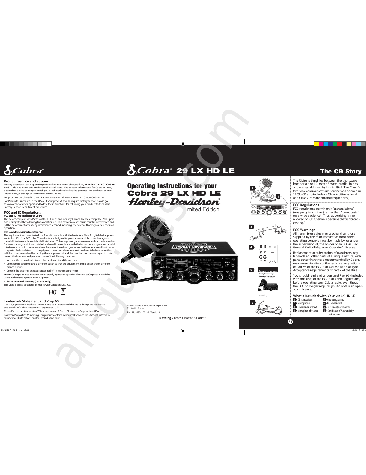
What’s Included with Your 29 LX HD LE
1. CB transceiver 5. Operating Manual
2. Microphone 6. DC power cord
3 Transceiver bracket 7. FCC rules (not shown)
4. Microphone bracket 8. Certificate of Authenticity
(not shown)
29 LX HD LE
©2014 Cobra Electronics Corporation
Printed in China
Part No. 480-1001-P Version A
Limited Edition
Nothing Comes Close to a Cobra®
Operating Instructions for your
Cobra 29 LX HD LE
The CB Story
A1
Product Service and Support
For any questions about operating or installing this new Cobra product, PLEASE CONTACT COBRA
FIRST…do not return this product to the retail store. The contact information for Cobra will vary
depending on the country in which you purchased and utilize the product. For the latest contact
information, please go to www.cobra.com/support
For products purchased in the U.S.A. you may also call 1-800-262-7212 (1-800-COBRA-12).
For Products Purchased in the U.S.A., if your product should require factory service, please go
to www.cobra.com/support and follow the instructions for returning your product to the Cobra
Factory Service Department for service.
FCC and IC Regulations
FCC and IC Information For Users
This device complies with Part 15 of the FCC rules and Industry Canada license-exempt RSS 210. Opera-
tion is subject to the following two conditions:(1) This device may not cause harmful interference;and
(2) this device must accept any interference received, including interference that may cause undesired
operation.
Radio and Television Interference
This equipment has been tested and found to comply with the limits for a Class B digital device,pursu-
ant to Part 15 of the FCC rules. These limits are designed to provide reasonable protection against
harmful interference in a residential installation. This equipment generates uses and can radiate radio-
frequency energy and,if not installed and used in accordance with the instructions, may cause harmful
interference to radio communications. However, there is no guarantee that interference will not occur
in a particular installation. If this equipment does cause interference to radio or television reception,
which can be determined by turning the equipment off and then on, the user is encouraged to try to
correct the interference by one or more of the following measures:
•Increase the separation between the equipment and the receiver.
•Connect the equipment to a different outlet so that the equipment and receiver are on different
branch circuits.
•Consult the dealer or an experienced radio/ TV technician for help.
NOTE: Changes or modifications not expressly approved by Cobra Electronics Corp.could void the
user’s authority to operate the equipment.
IC Statement and Warning (Canada Only)
This Class B digital apparatus complies with Canadian ICES-003.
Trademark Statement and Prop 65
Cobra®, Dynamike®, Nothing Comes Close to a Cobra® and the snake design are registered
trademarks of Cobra Electronics Corporation, USA.
Cobra Electronics Corporation™ is a trademark of Cobra Electronics Corporation, USA.
California Proposition 65 Warning:This product contains a chemical known to the State of California to
cause cancer, birth defects or other reproductive harm.
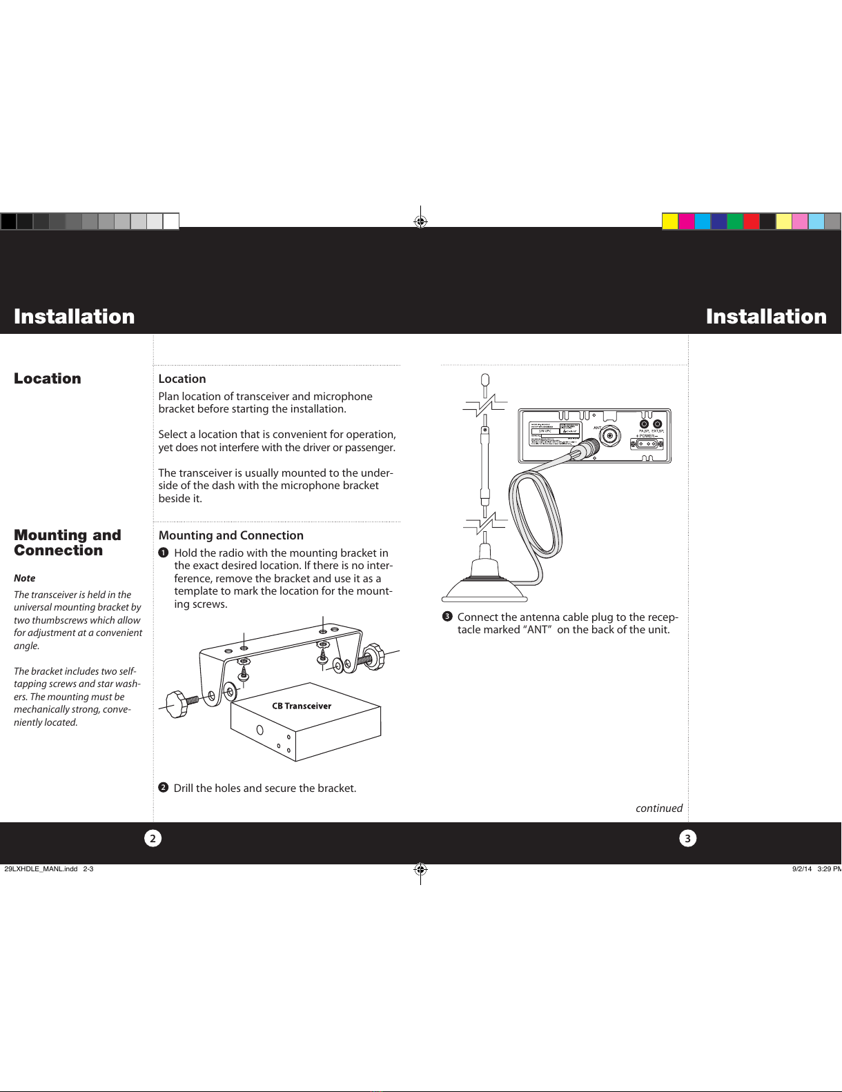
3
2
5
6
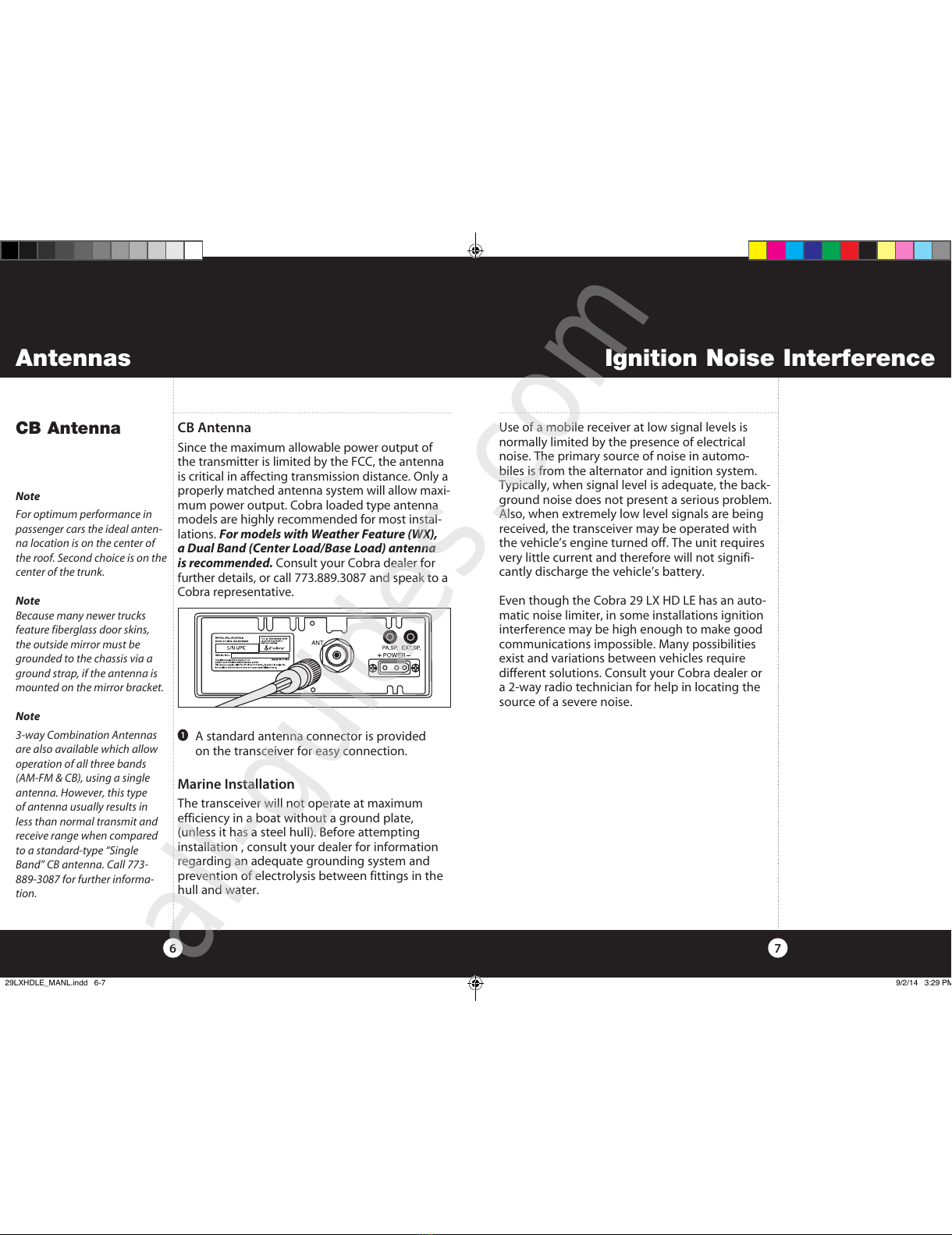
1