Coinco BillPro Operation manual

BillPro Bill Acceptor
Operation and Service Manual
TM


3
TABLE OF CONTENTS
Section 4: Maintenance
Disassembling the BillPro ................................... 10
Disassembling the Chassis .................................. 13
Disassembling the Lower Housing ..................... 15
BillPro Cleaning Maintenance Procedure ........... 17
Cleaning Salt Water Damage ............................. 17
Section 5: Troubleshooting
Introduction ......................................................... 18
BillPro Diagnostic Flash Codes .......................... 18
Section 6: Parts List
Main Frame (BP) ............................................... 19
Lower Housing Assembly .................................. 21
Chassis Assembly ............................................... 23
Intermediate Frame Assembly ............................ 24
Cashbox Assembly ............................................. 24
Section 1: General Information
Introduction ........................................................... 4
Models .................................................................. 4
For Your Records ................................................. 4
Features ................................................................ 4
After Unpacking ................................................... 4
Main Logic Board Assembly ................................ 4
Specifications ........................................................ 5
Dimensional Drawing ........................................... 5
Section 2: Installation
Options Setting ...................................................... 6
Setting the Configuration Options ......................... 6
Installing the Bill Acceptor.................................... 6
Section 3: Operation
BillRecognition ..................................................... 7
BillValidation ........................................................ 7
Bill Stacking and Credit ........................................ 7
BillRejection ......................................................... 7
Component Explanation
Bill Transport and Stacking ............................ 7
Left and Right Alignment Sensors ................. 7
Center Optic Sensor ....................................... 7
Left and Right Optic Sensor ........................... 7
Magnetic Sensor ............................................. 7
Anti-Pullback Levers ..................................... 7
Stacker Home Sensor .................................... 7
Encoder Sensor .............................................. 7
Component Explanation Drawing ................... 8
Interconnect Drawing (BP) .................................. 9

4
SECTION 1: GENERAL INFORMATION
INTRODUCTION
This manual contains information on installing, operating
and maintaining Coinco's BillPro Series bill acceptors.
This manual is intended for owners, route operators and
shop-level technicians as a primary source of informa-
tion. Taking time to read this manual and becoming
familiar with this information will help you obtain the best
performance from your Coinco bill acceptor.
MODELS
BillPro Series bill acceptors are self-contained units
designed to work with MDB vendors. Listed below are
some of the models available:
BP2BX BillPro bill acceptor, 2 bill acceptance
($1 & $5), Bottler mask & MDB
interface only
BP4BX BillPro bill acceptor, 4 bill acceptance
($1, $5, $10 & $20), Bottler mask &
MDB interface only
BP4SX BillPro bill acceptor, 4 bill acceptance
($1, $5, $10 & $20), Snack mask &
MDB interface only
BP2BX and BP4BX bill acceptors are primarily used in
cold drink vendors which use MDB interface. The
BP4SX bill acceptor are primarily used in MDB snack,
coffee or food machines.
BillPro units support MDB communication only.
FOR YOUR RECORDS
A label indicating the model number and serial number is
affixed to the back of the bill acceptor. Refer to the
model and serial number whenever you call upon your
Coinco Service Center for information or service. The
first four digits of the serial number contain the manufac-
turing date code which indicates the beginning of the
warranty period.
EXAMPLE: Serial number 260300135. First and
second digits indicate the week of manufacture. The
third and fourth digits indicate the year (the 26th
week of 2003).
FEATURES
• Modular design
• Illuminated Inlet
• Flash programmable memory
• Exceptional acceptance rate
• Anti-jam software
• Flex stack bill box
• Center drive belt
• Scalloped bill path for wet bill acceptance
• State-of-the-art electronic logic system
• Programmable acceptance of the following bills:
$1, $5, $10 and $20.
• Vandal resistant design protects against: saltwater,
bill pullback, counterfeit bills.
• Utilizes standard mounting
• 34 V Multi-Drop Bus interface
• High impact, non-corrosive plastic construction
• Easily accessible bill path
• Self-diagnostics communicated via status light
• Manufactured and supported by Coinco.
• Made in the U.S.A.
AFTER UNPACKING
After unpacking the unit, inspect it for any possible
shipping damage. If the unit is damaged, notify the
shipping company immediately. Only the co-signee (the
person or company receiving the unit) can file a claim
against the carrier for shipping damage. We recommend
that you retain the original carton and packing materials
to reuse if you need to transport or ship your acceptor in
the future.
If the bill acceptor is being stored or used as a spare,
always keep it in its shipping carton when not in use.
This will keep it clean and offer the best protection for
the unit.
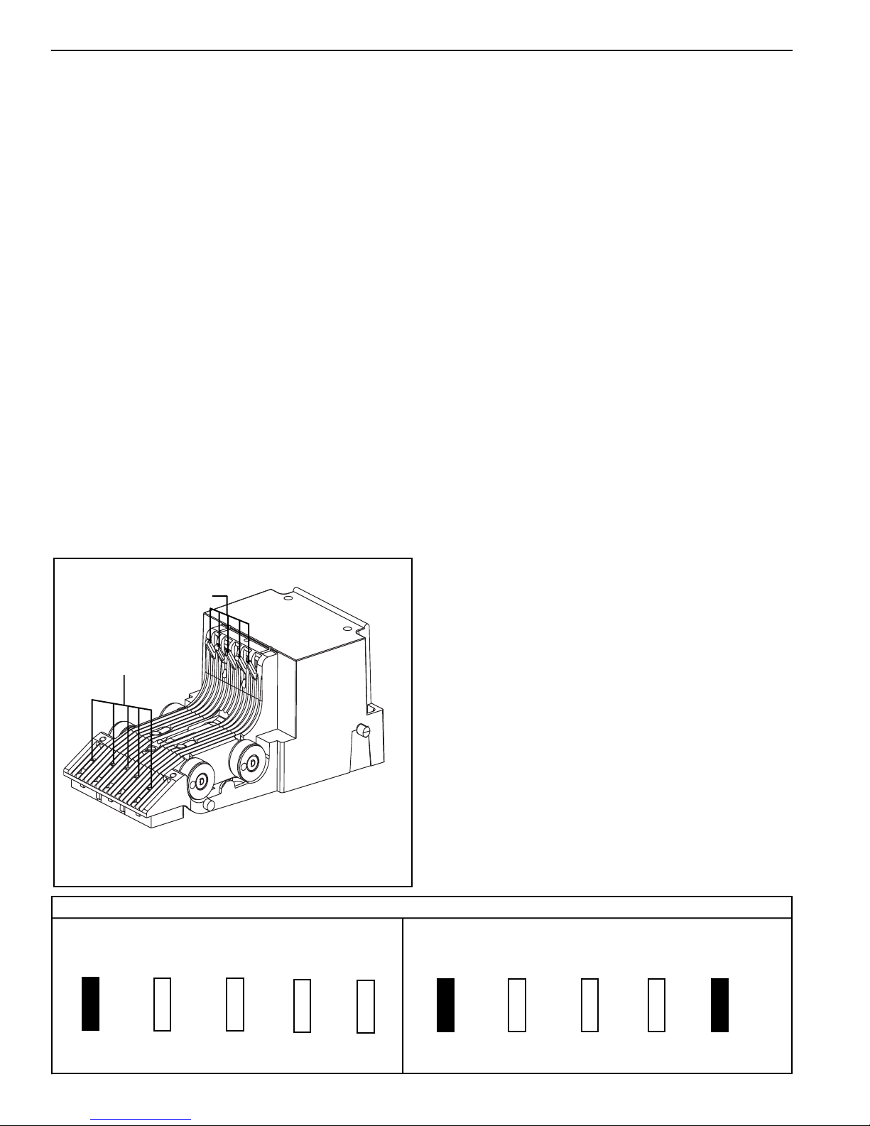
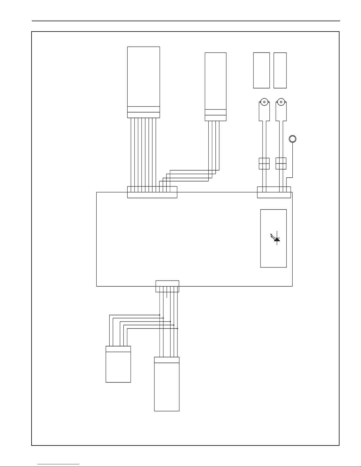
MAIN LOGIC BOARD ASSEMBLY
The main logic board contains the microprocessor which
controls all the functions of the bill acceptor based on
information from the vending machine, coin mechanism
and various bill acceptor sensors.
Also contained on the main logic board are lower optic
sensors and the power supply which receives its primary
voltage from the vending machine. The 34 VDC
(MDB) primary voltage is filtered and reduced for the
main logic board.

5
SECTION 1: GENERAL INFORMATION
Dimensions and Specifications
Figure 1
Power Requirements
22 to 45 VDC
0.2 Amp average standby
2.5 Amp average operating
Operating Temperature
0°F to 150°F
-18°C to 65°C
Storage Temperature
-22°F to 165°F
-30°C to 74°C
Relative Humidity
5% to 95% non-condensing
Physical Weight in Shipping Carton
4 pounds
Dimensions shown in inches
BP2BX, BP4BX BP4SX

6
Anti-cheat lever
Inlet LEDs
OPTION SETTINGS
The eight different configuration options and the
order in which they are stored in the bill acceptor
are as follows:
• $1 accepted with high security disable
• $1, $5 accepted with high security disable
• $1, $5, $10 accepted with high security disable *
• $1, $5, $10, $20 accepted with high security disable *
• $1 accepted with high security enable
• $1, $5 accepted with high security enable
• $1, $5, $10 accepted with high security enable *
• $1, $5, $10, $20 accepted with high security enable *
Configuring the bill acceptor for bill enabling and
security is accomplished using the anti-cheat lever
and the illuminated inlet. The anti-cheat lever is used
to enter configuration programming mode, scroll
through all possible configuration options and select
the required configuration. The illuminated inlet
provides feedback to the user during the configuration
process by displaying a pattern that corresponds to
each configuration option available.
SECTION 2: INSTALLATION
Figure 2
INSTALLING THE BILL ACCEPTOR
1. Remove the vending machine's power.
2. Install the BillPro Series bill acceptor into the mounting
hole of the vending machine using the appropriate
hardware (NOT INCLUDED).
NOTE: Should additional mounting hardware be
required, please contact your local Coinco office
or machine manufacturer
3. Connect the BillPro MDB interface harness to the the
vending machine and coin changer.
4. Restore power to the vending machine (illuminated inlet
will begin to flash and stacker motor will cycle upon
power-up).
5. Observe that the power indicator light, on the back of
the lower housing, is ON continuously. If the light is
OFF or blinking, check the following:
-Power to machine
-Machine disabling unit
-Bill acceptor harness
-Machine does not have credit already established
6. With the vend price set below one dollar, insert a one
dollarbill.
7. Verify the dollar bill is accepted and stacked into the
billbox.
8. Verify a one dollar credit has been established.
Lower Housing
$1 $5 $10 $20 Security $1 $5 $10 $20 Security
• Remove the lower housing.
• With power applied, depress and release the anti-cheat lever
five times, holding it down for a half a second each time.
• Once in the configuration mode, depress and release the
anti-cheat lever one time to scroll to the next configuration
option. Continue depressing and releasing the anti-cheat
lever until the desired option is reached.
• Once the desired option is displayed, depress and hold the
anti-cheat lever until the unit exits the configuration mode
(approximately 3 seconds). The new configuration setting
will flash 3 times to confirm the setting.
• Replace the lower housing.
• Test unit to insure proper set-up.
SETTING THE CONFIGURATION
OPTIONS (see Figure 2)
* Options available for BP4 only.
This example shows $1 enable and high security
disable
This example shows $1 enable and high security
enable
Inlet Leds

7
BILL RECOGNITION
When a bill is inserted into the bill acceptor and it blocks
the left and right alignment sensors as well as the center
optic sensor, the transport motor begins to run.
BILL VALIDATION
From the time the transport motor begins to run until the
trailing edge of the bill leaves the alignment sensors,
optical and magnetic sensors send information to the
microprocessor to determine the validity of the bill.
BILL STACKING AND CREDIT
If the bill is determined to be authentic, it is transported to
the stack position. Once the sensors of the lower
housing’s anti-pullback lever signals the microprocessor
that the bill is in the stacking position, the stacker motor
runs and credit is given.
BILL REJECTION
If the bill is determined to be invalid, the wrong denomi-
nation or the anti-pullback levers are active when the bill
is determined to be in the stack position, the transport
motor will reverse returning the bill to the customer.
COMPONENT EXPLANATION
(see Figure 3)
Bill Transport and Stacking
The bill transport system is composed of a motor and
gearcase assembly and two sets of pulleys and belts.
When the transport motor is energized, it pulls the bill in
by sandwiching it between the lower housing rollers and
the chassis belts. During the validation process, the bill is
transferred from the lower housing rollers and chassis
belts to the intermediate frame and rollers.
The bill stacker is composed of a motor and gearcase
assembly and a pusher plate assembly. When the bill is
transported past the anti-pullback levers into the stacking
position, the stacker motor energizes driving the pusher
plate, which in turn, pushes the bill into the bill box.
Left and Right Alignment Sensors
The left and right alignment sensors send information to
the microprocessor to insure that the bill is the right width
and that it is being fed in correctly.
Center Optic Sensor
The center optic sensor informs the microprocessor that
the bill is ready to be transported if the information from
the alignment sensors is correct.
Left and Right Optic Sensors
The left and right optic sensors and associated circuitry
perform various optical checks on the bill and send that
information to the microprocessor for bill validation.
Magnetic Sensor
The magnetic sensor and its associated circuitry per-
forms checks on the magnetic properties of the bill and
sends that information to the microprocessor for bill
validation.
Anti-Pullback Lever
The lower anti-pullback lever is optically monitored to tell
the microprocessor when the bill has entered the stack
position or if an attempt to defraud the unit is taking
place.
Stacker Home Sensor
The stacker home sensor is an optical sensor that
informs the microprocessor of the position of the stacker
pusher plate.
Encoder Sensor
Connected to the transport motor is an encoder wheel
which is optically monitored to determine the speed of
the transport motor and to determine the position of the
bill in the bill path.
SECTION 3: OPERATION

8
SECTION 3: OPERATION
Figure 3
Component Explanation
Bill Box Lid
Intermediate Frame
Flex Stack
Bill Box
Lower
Housing
Center Drive
Belt
Left
Alignment
Sensor
Chassis Belt
Anti-Pullback
Lever
Pusher
Plate
Stacker Home
Encoder Sensor
Right
Alignment Sensor
Pushplate
Assy
Center Optic
Left-Right
Optic
Rollers

9
SECTION 3: OPERATION
Interconnection
BP
BillPro
Main Logic Board
(408500)
To
Changer
To
Multi-Drop
Bus
Upper Sensor
Board (408501)
Stacker Board
(408502)
8
7
6
5
4
3
2
1
8
7
6
5
4
3
2
1
4
3
2
1
4
3
2
1
Transport Motor
Assembly
(407254-5)
Stacker Motor
Assesmbly
(407253-8)
(Red Dot)
(Red Dot)
Ground
Terminal
(60302-2)
(60302-2)
Blue
Red
2
2
1
1
2
12
1
2
1
2
1
3
4
5
3
4
5
P2
Externally Visible
LED
VE2
+12V
Encoder Wheel
Stacker Home
1
2
3
4
5
6
1
2
3
4
5
6
P1
P.P
4
2
3
1
5
6
4
2
3
1
5
6
1
2
3
4
5
6
7
8
9
10
11
12
1
2
3
4
5
6
7
8
9
10
11
12
P3
+12
GND
Analog MAG
LED Anode Drive
Center Trans. and Center Refl.
Right Trans. and Left Skew
Left Trans. and Right Skew
Center Refl. Out
Figure 4

10
DISASSEMBLING THE BILLPRO
Removing the Bill Box (see Figure 5)
Push the bill box tab forward while sliding the bill
box up.
Figure 5
Bill Box Tab
Removing the Lower Housing
(see Figure 6)
To remove the lower housing, push the locking tab on the
bottom of the bill acceptor and pull the lower housing to
the rear.
SECTION 4: MAINTENANCE
Figure 6
Main
Frame
Locking Tab
Lower
Housing
Bill Box

11
SECTION 4: MAINTENANCE
Removing the Inlet Mask
(see Figure 8)
Using a Phillips screwdriver, remove the three screws
that secure the mask to the mounting frame.
Removing the Mounting Frame and Static
Grounding Spring (see Figure 8)
Using a Phillips screwdriver, remove the screws that
attach the mounting plate and grounding spring to the
main frame.
Figure 8
Main Frame
Bottler
Mask
Snack
Mask
Mounting
Frame
Mounting
Frame
Static Ground
Spring
Static Ground
Spring Nuts
Main Frame
Intermediate Frame
Figure 7
Tab
Lower
Locking Tab
Detail
Upper
Locking Tab
Detail
Lower
Tab
Removing the Intermediate Frame
(see Figure 7)
Using a small straight tip screwdriver, free the ten
locking tabs which secure the intermediate frame to the
main frame and remove the intermediate frame.

12
Removing the Chassis from the Main-
frame (see Figure 10)
Remove the phillips screw securing the chassis to the
main frame. Spread the main frame apart to release the
two locating pins of the chassis from the main frame then
pull down on the chassis. Carefully feed the chassis
harness through the opening in the main frame. Pull the
chassis out through the lower main frame opening.
Figure 10
Main Frame
Chassis
Chassis
Figure 9
Removing the Upper Sensor Board from
the Chassis (see Figure 9)
Remove upper PCB cover by unsnapping from front.
Using a small Phillips screwdriver, remove two screws
securing the upper PCB to the upper enclosure. Unplug
the chassis harness from the upper sensor board. Lift
board straight up and then forward to remove.
Upper Sensor
Board
SECTION 4: MAINTENANCE
Screw
PCB
Cover
spread

13
SECTION 4: MAINTENANCE
Removing the Encoder/Sensor Housing
Board Assembly (see Figure 12)
Remove sensor housing by tilting up and away from
transport motor gear case assembly, then pull straight
out. Unplug harness connection.
Figure 12 Stacker/Encoder
Housing & Board
Assembly
Chassis
DISASSEMBLING THE CHASSIS
Removing the Pusher Plate from the
Chassis (see Figure 11)
Remove the pusher plate from the stacker gear box
assembly by slightly spreading the pusher plate until it
clears the stacker motor cam assembly. Pull the pusher
plate straight out until the locking tabs of the stacker
slides catch the chassis. Using a small screwdriver,
release the four tabs and remove the pusher plate.
Figure 11
Chassis
Locking Tabs
(both sides)
Locking
Tabs
Screwdriver
Stacker
Motor Cam

14
Removing the Transport and Stacker
Motor Assemblies (see Figure 14)
Unplug motor wires from two connectors located on
each side of chassis. Compress the belt tensioning spring
by pushing up on the stacker motor and gear case
assembly until the three locking tabs of the gear case can
be freed from their mating slots in the chassis. Remove
the stacker motor and gear case assembly along with the
tensioning spring. Slide the transport motor and gear case
assembly down until its three locking tabs are freed from
their mating slots on the chassis.
Removing the Chassis Belts and Pulleys
(see Figure 13)
Compress the belt tensioning spring by pressing down on
the transport motor and gear case assembly and remove
the belts. Slide the pulleys off the lower shafts to prevent
them from falling off.
SECTION 4: MAINTENANCE
Figure 14
Chassis Belt
Pulley
Belt Tension
Spring
Stacker Gearbox
& Motor Assembly
Transport
Assembly
Slots
Stacker
Assembly
Slots
Transport Gearbox
& Motor Assembly
Figure 13
Chassis
Belt
Chassis
Belt
Transport Motor
Assembly
Motor
Connector

15
SECTION 4: MAINTENANCE
Removing the Mag Roller and Spring
(see Figure 16)
Lift lower enclosure out of the lower housing.
Figure 15
Figure 16
DISASSEMBLING THE LOWER
HOUSING
Removing the Printed Circuit Board
(see Figure 15)
Using a small straight screwdriver, pry up at the two
outer tabs on the lower PCB cover. Pivot the front of
the cover up and then slide forward. Lift the board out
by gently pulling up on the harness.
PCB
Bottom
Cover
Lower
Housing
Logic Board
Shroud
Spring
Lower PCB Enclosure
PCB Cover
Outer Tabs

16
SECTION 4: MAINTENANCE
Removing the Lower Housing
Anti-Pullback Lever and Spring
(see Figure 17)
Using a small drift or Phillips screwdriver, depress the
locking tab in the small hole in top of the lower housing.
At the same time, insert a small standard blade screw-
driver into the center slot and push the anti-pullback
assembly back out of the retaining tabs.
Remove the anti-pullback lever from its mount by
releasing the locking tabs. Pay close attention to the
placement of the spring to assure its correct position on
reassembly.
Removing the Lower Housing Rollers
and Pulleys (see Figure 18)
Slide the front pulleys off the shaft.
To remove the center belt, slide the back pulleys off the
shaft. Gently tap the back shaft with a small hammer
until the shaft splines are free from the center pulley.
Figure 18
Back Pulley
Shaft
Front Pulley
Figure 17
Anti-Pullback
Lever
Spring Anti-Pullback
Mount

17
SECTION 4: MAINTENANCE
BILLPRO CLEANING PROCEDURE
FOR SALT WATER POLLUTED
UNITS
NOTE: Petroleum-based cleaners and freon-based
propellants can damage plastic and some electronic
components. Scouring pads and stiff brushes may
harm the circuit boards and mar the plastic. These
items should never be used when cleaning the BillPro
bill acceptor.
Procedure
1. Remove power from the bill acceptor.
2. Remove the bill acceptor from the vending machine.
3. Open the bill box lid and verify that the stacker plate
is in the standby/home position. If it is not in the
home position, apply power and observe that the
stacker plate returns home.
4. Remove the bill box.
WARNING: If moisture is present, allow the unit to
dry thoroughly before applying power to avoid
possible shock hazard. If the stacker plate does not
return to the home position, remove power and
carefully remove the bill box to avoid damaging the
bill box and/or stacker plate.
5. Remove the lower housing.
6. Remove the bottom cover of the lower housing.
7. Run hot water (110°-140°F) over the lower housing
from the top. Using a soft brush, gently clean any
salt residue. Use a soft, absorbent cloth to clean
residue off the lower housing. Allow the unit to dry
for 24 hours before applying power.
8. Remove the front mask. Using hot water and a soft
brush, clean the front mask, upper sensor board
cover and main frame anti-pullback levers.
CAUTION: The motors are not protected from water,
therefore the unit must be held in a manner that
prevents water from running over them.
9. Verify the anti-pullback levers move freely and that
the spring returns them to their extended position.
10. Allow the unit to dry thoroughly.
11. Clean the magnetic head using a swab and isopropyl
alcohol.
12. Replace the front mask.
13 Replace the lower housing cover.
14. Place the lower housing into the main frame.
15. Remount the bill box.
16. Apply power and insert bills to verify the unit is
functioning properly.
BILLPRO CLEANING
MAINTENANCE PROCEDURE
NOTE: Petroleum-based cleaners and freon-based
propellants can damage plastic and some electronic
components. Scouring pads and stiff brushes may
harm the circuit boards and mar the plastic. These
items should never be used when cleaning the BillPro
bill acceptor.
The BillPro should be cleaned every 20,000 bills or every
two years (or as needed, depending on the environmental
conditions of the location). Dust can be removed with a
soft brush or cloth or it can be blown out using com-
pressed air.
Procedure
1. Disconnect power from the bill acceptor.
2. Remove the bill box and use a soft cloth to wipe any
dust from around the intermediate frame and
stacker plate.
3. Remove the lower housing.
4. Using compressed air or a soft brush, blow or brush
the dust off of the optic sensors.
5. Remove dust from around the rollers on the lower
housing and the sensors on the upper sensor board.
The upper sensors are located directly above the
lower housing sensors when the lower housing is
installed.
6. The bill path can be further cleaned of any dirt or oil
by using a soft cloth moistened with a mild soap and
water solution.
7. Clean the magnetic head with a cotton swab and
isopropyl alcohol.
8. Remove dust from the transport belt areas and any
other places of build up.
9. Once the lower housing is dry, place it back into the
mainframe making sure the tab on the bottom locks
into place.
10. Remount the bill box.
11. Apply power and insert bills to verify the unit is
functioning properly.

18
SECTION 5: TROUBLESHOOTING
INTRODUCTION
The Troubleshooting Guide on this page is intended to
help locate problems within the bill acceptor. If a bill
acceptor cannot be repaired by following this guide,
return the unit to the nearest Coinco Service Center for
repair along with a complete description of the problem
you are having with the bill acceptor.
Logic troubleshooting minimizes the time spent in remov-
ing and replacing parts that are not defective. Some
failures are caused by minor problems such as dirt or
loose/faulty connections. Please check the following
before replacing any parts:
• Clean any dirt or dust from the bill path.
• Vending machine is not disabling unit.
• Connectors are inserted correctly.
• Connector pins are not bent or broken.
• All wires are properly secured.
BILLPRO DIAGNOSTIC CODES
Troubleshooting can be done by reading the number of
flashes or blinks of light from the LED at the bottom of
the BillPro bill acceptor. Refer to Figure 19.
Flash Code Error Condition
1 Check bill box
2 Check/Clean bill path
3 Return for service
NOTE: A scrolling light, in the illuminated
inlet, indicates normal operation. If all LEDs
are not illuminated then, the unit has been
disabled by the Vending Machine Controller.
Figure 19
Flash code
LED
Flash Codes
The BillPro supports the following flash codes
for troubleshooting the unit in the field.

19
SECTION 6: PARTS LIST
MAIN FRAME
BillPro
ITEM PART DESCRIPTION QTY. NOTES
NO. NO.
1 921401 Screw 3
2 925305 Bottler Mask 1
408576 Security Bottler Mask 1 Used on BP2BXM and BP4BXM
3 925511 Snack Mask 1
4 345-6R6 Screw 5
5 920807-6 Main Frame 1
6 920065-2 Mounting Frame, Bottler 1
7 921492 Mounting Frame, Snack 1
8 925290 Grounding Spring 1
9 438-6 Hexnut & Lock Washer 3
10 925402 BillPro Front Label 1 Bottler
925505 BillPro Front Label 1 Snack
1
1
4
4
4
4
4
3
5
6
9
2
8
7
8
10

20
SECTION 6: PARTS LIST
LOWER HOUSING ASSEMBLY
11
15
18
3
13
12
10
14 7
5
19
17
4
2
6
16
14
1
8
Table of contents
Popular Vending Machine manuals by other brands

BIANCHI VENDING
BIANCHI VENDING LEIsa Use and maintenance manual

VKI Technologies
VKI Technologies Eccellenza Momentum Operation manual

Westomatic
Westomatic Sigma Touch Operator's & installation manual

Wittenborg
Wittenborg 9100 Cleaning guide

HOTWORX
HOTWORX HWINF5C manual

One-Touch Drinks
One-Touch Drinks Atlas user manual

ELAUT
ELAUT BIG ONE XTREME II OPERATOR (USER) & SERVICE MANUAL

VT
VT VendMine Connect T313 user manual

Westomatic
Westomatic primo MINI manual

N&W Global Vending
N&W Global Vending Diesis 500 Installation operation & maintenance

Dixie Narco
Dixie Narco DN 55 Series Technical manual

Coastal Amusements
Coastal Amusements LUCKY DUCK user manual