Cole Parmer SP-300 Series User manual

Instruction Manual
061672-CPB Rev D
Cole-Parmer®
SP-300 Series
Spectrophotometer
Accessory Fitting & Operation

2
Safety
Please read this information carefully prior to installing or using this equipment.
1. The unit described in this manual is designed be operated only by trained personnel. Any adjustments,
maintenance and repair must be carried out as defined in this manual, by a person qualified to be aware
of the hazards involved.
2. It is essential that both operating and service personnel employ a safe system of work, in addition to
the detailed instructions specified in this manual.
3. Other than for those items defined in the maintenance procedures herein there are no user serviceable
items in this instrument. Removal of covers and attempted adjustment or service by unqualified personnel
will invalidate the warranty and may incur additional charges for repair.
4. References should always be made to the Health and Safety data supplied with any chemicals used.
Generally accepted laboratory procedures for safe handling of chemicals should be employed.
5. If it is suspected that safety protection has been impaired in any way, the unit must be made inoperative
and secured against any intended operation. The fault condition should immediately be reported to the
appropriate servicing authority.

3
SECTION 1 – Accessories and Spare Parts
1.1 OPTIONAL ACCESSORIES
Order Code
83070-39
83070-31
83070-33
83070-35
83070-37
83070-41
83070-43
83056-80
83056-82
83070-51
83054-90
-
99610-35
83058-94
90238-26
99959-79
Description of Accessory
Internal printer
Automatic 8 cell turret
Sipper pump
Peltier
Combined sipper peltier pump
10x10mm path length cuvette holder
16/24mm test tube holder
10 x 100mm path length cuvette holder
10x10 (70µl cell holder)
Water heated 10x10 single cell holder
Visible calibration set
UV/Visible calibration set
Moulded cuvette rack for 16 10x10mm cuvettes
Dust cover
2GB USB memory sticks for external memory
RS232 to USB converter for use with computer without a serial port
1.2 CONNECTING THE ACCESSORIES
There are two types of accessories which can be fitted in the sample chamber – passive or active
accessories. The range of passive accessories includes 10 x 10mm single cuvette holders, single water
heated cuvette holders, adjustable path length (10 to 100 mm) cuvette holders, test tube holders,
boiling tube holders, film holders and micro-cuvette holders. The range of active accessories includes an
automated 8 cell changer, sipper pump, peltier and combined peltier sipper pump. The instrument must
be turned off before any accessories are fitted.
1.2.1 INTERNAL PRINTER
Use a small screw driver to lift the blanking panel on the
top of the instrument. Squeeze the two clips in order to
remove the blanking panel. Disconnect the printer wires
which are secured to the underside of the blanking plate.
Unpack the printer from the packaging. Turn the printer
upside down and connect the printer wires by clipping
into the connector on the printer.
Clips
Part Code
660101
735401
735201
735301
735701
630204
637071
630005
630304
736201
035088
035091
060422
735001
019146
037551

4
Squeeze the grey plastic clips together so that the printer
top opens. Slot the printer into the top of the instrument
and push down until it fits flush to all four sides.
Insert the paper roll into the printer – ensuring that there
is some paper sticking out of the printer before clicking
the grey plastic back into place. Switch the instrument
on. The power and error lights on the printer will flash.
Once the instrument power on tests are complete press
the feed button to check that the paper is fed correctly.
1.2.2 PASSIVE ACCESSORIES
Unscrew the thumb screw to undo the passive accessory.
Lift out the passive accessory. To fit a different passive
accessory simply place the accessory in the correct
orientation, align the thumb screw and tighten to fix in
place.
To replace the passive accessory with an active accessory
refer to section 1.2.3.
1.2.3 ACTIVE ACCESSORIES
Unscrew the thumb screw to undo the passive accessory.
Lift out the passive accessory. To fit an active accessory
unscrew screws 1 to 4 and lift out the metal base plate.
This will expose the bottom of the sample chamber with
the power supply connection needed to operate the
active accessories.
2.
4.
1.
3.
Thumb
screw
Thumb
screw

1.2.3.1 Automatic 8 cell turret
Take the 8 cell turret base plate. Connect the power
supply in the bottom of the sample chamber to the
connector on the underside of the baseplate. Place the
base plate in the sample chamber. Replace screws 1 to 4.
Take the 8 cell carousel and place on top of the motor,
taking care to align the three ball bearings with the
grooves on the motor shaft. Gently push the carousel
down onto the motor shaft until it is located into place.
Gently rotate the carousel until there is some resistance.
The carousel is now in the correct position.
If the fitting is too tight use a small screw driver to loosen
the ball bearings before pushing the carousel down onto
the shaft.
1.2.3.2 Peltier
For this accessory as well as removing the passive
accessory base plate, the front panel of the instrument
must also be removed. Loosen screws 5 and 6 until the
front panel can be lifted out in the forwards direction.
Take the peltier base plate. Connect the power supply
in the bottom of the sample chamber to the connector
on the underside of the base plate. Place the base plate
in the sample chamber. Replace screws 1 to 4. Take the
peltier front panel and slot into place before retightening
screws 5 and 6.
When the accessory is fitted the instrument will look like
this.
5
5.
6.

6
1.2.3.3 Sipper pump
For this accessory as well as removing the passive
accessory base plate, the front panel of the instrument
must also be removed. Loosen screws 5 and 6 until the
front panel can be lifted out in a forward direction.
Take the sipper base plate. Connect the power supply
in the bottom of the sample chamber to the connector
on the underside of the base plate. Place the base plate
in the sample chamber. Replace screws 1 to 4. Take the
sipper front panel and slot into place before re-tightening
screws 5 and 6.
The tubing should be connected depending on the
function that the sipper pump is going to perform. All
tubing must be kept as short as possible and the tubing
must not be allowed to obstruct the ligth path.
For sipping:
1. Connect the sipper pump tubing to the outlet port on
the flow-through cuvette.
2. Secure the tubing using the clip on the righthand side
of the pump head.
3. Ease the tubing round the rollers by carefully rotating
them clockwise, by hand. Clamp the tubing into the clip
on the left hand side of the motor.
4. Once secured, ensure the tubing is routed into the two
retaining clips located on the base plate at the side of the
pump head.
5. Cut the tubing at the point where it fits comfortably
onto the left hand tube located on the inside of the front
bulk head.
6. Connect a suitable length of this tubing to the external
waste pipe.
Bi directional flow A
(sipping)
Continuous flow
1.
7.
3.
4.
9.
6.
5. 8.
2.
Bi directional flow B
(pumping)
5.
6.

7
7. Cut a small length of the sipper pump tube and push
this over one end of the capillary tube. Connect this to
the inlet port of the flow-through cuvette.
8. Route the tube into the two retaining clips located on
the base plate at the side of the pump head.
9. Fit the sipper probe and secure using the thumbscrew.
Feed the capillary tubing through the tube and up
through the sipper probe, allowing sufficient length for it
to pass into a suitable receptacle.
For pumping:
1. Cut two pieces of sipper pump tubing approximately
300mm in length. Take one length of tubing and fit this
to the pump head, as shown, securing the tubing using
the clip on the right hand side of the pump head.
2. Ease the tubing round the rollers carefully rotating
them clockwise, by hand. Clamp the tubing into the clip
on the left hand side of the motor.
3. Fit the other end onto the inlet port on the flow-
through cuvette.
4. Fit the second 300mm length of tubing to the outlet
port of the flow-through cuvette. Once secured, ensure
the tubing is routed into the two retaining clips located
on the base plate at the side of the pump head.
5. Fit the other end of the tubing onto the outlet port,
located on the inside of the front bulkhead.
6. Connect a suitable length of sipper pump tubing to
the external outlet port.
7. Insert one end of the capillary tube into the sipper
pump tubing, as shown.
8. Feed the other end through the inlet port located on
the inside of the bulkhead.
9. Fit the sipper probe and secure using the thumbscrew.
10. Carefully feed the tubing through the sipper probe,
allowing sufficient length for it to pass into a suitable
receptacle.
When the sipper accessory has been fitted and the tubing
has been connected the instrument will look like this.
1.2.3.4 Combined sipper peltier pump Refer to section 1.2.3.3 for more details.
1.
7.
3.
4.
9.
10.
6. 5. 8. 2.

8
1.3 USING THE ACCESSORIES
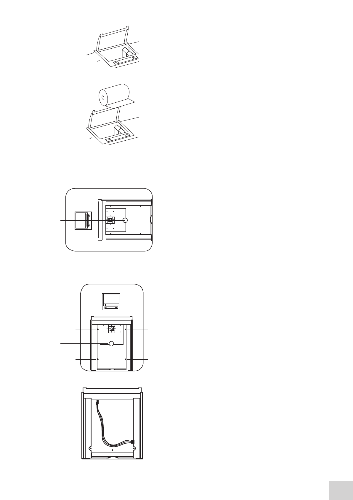
1.3.1 Automatic 8 cell turret
When the automatic 8 cell turret is in use the 8 cell turret
icon is displayed in the bottom right hand corner of the
screen. The current cell position is displayed adjacent to
the 8 cell turret icon. The 0 position should always be used
for the zero calibration sample.
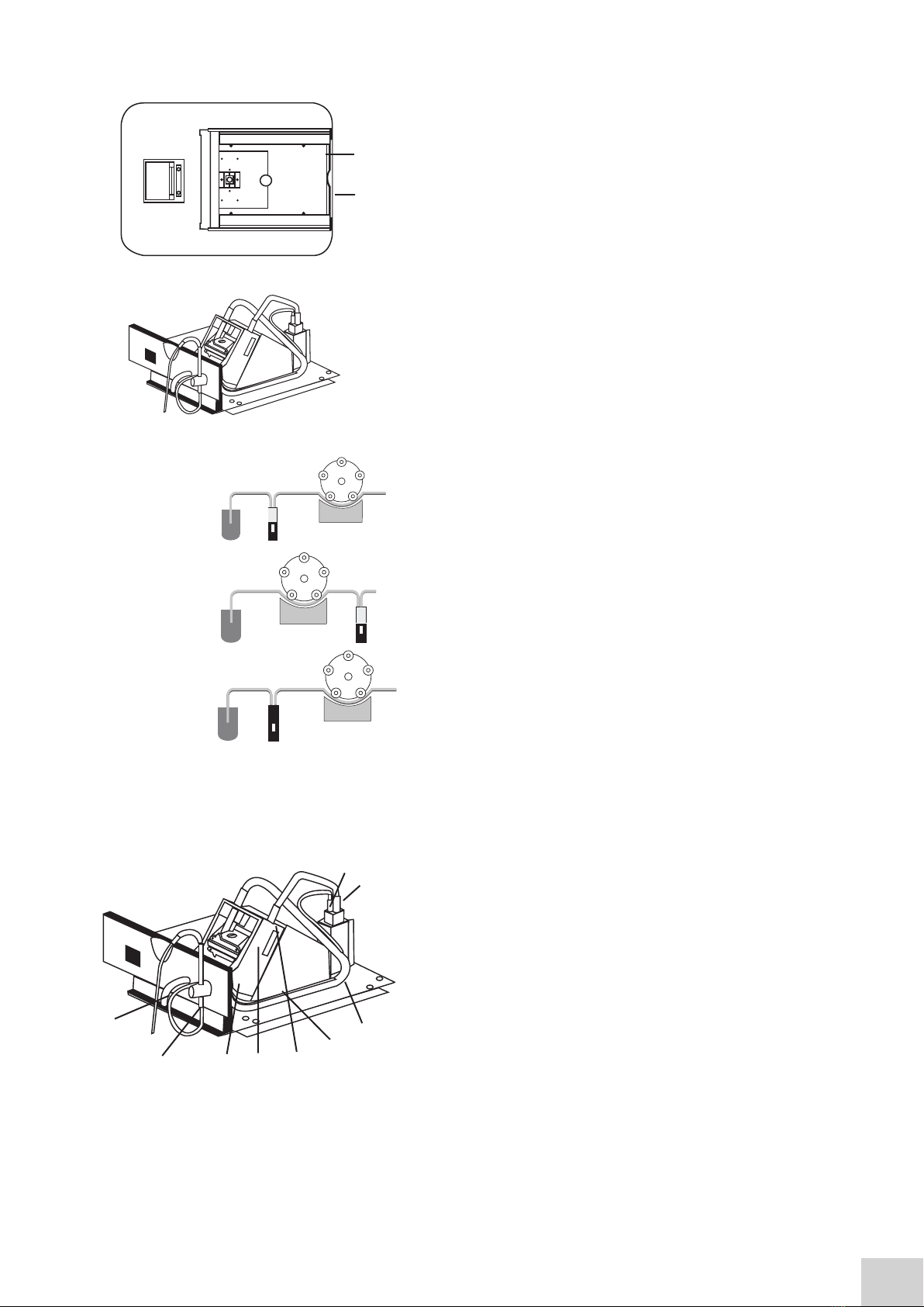
To perform measurements using the automatic 8 cell turret, insert the cuvettes containing the samples
into turret positions 1 to 7. Insert the cuvette containing the blank solution into turret position 0. Enter
the required measurement mode and set up the required measurement parameters. Press the key below
the calibrate to zero icon. The instrument will automatically move the turret around to position zero to
perform the measurement. Once the calibration is complete the measure sample icon will appear and
the turret will return to its original starting position.
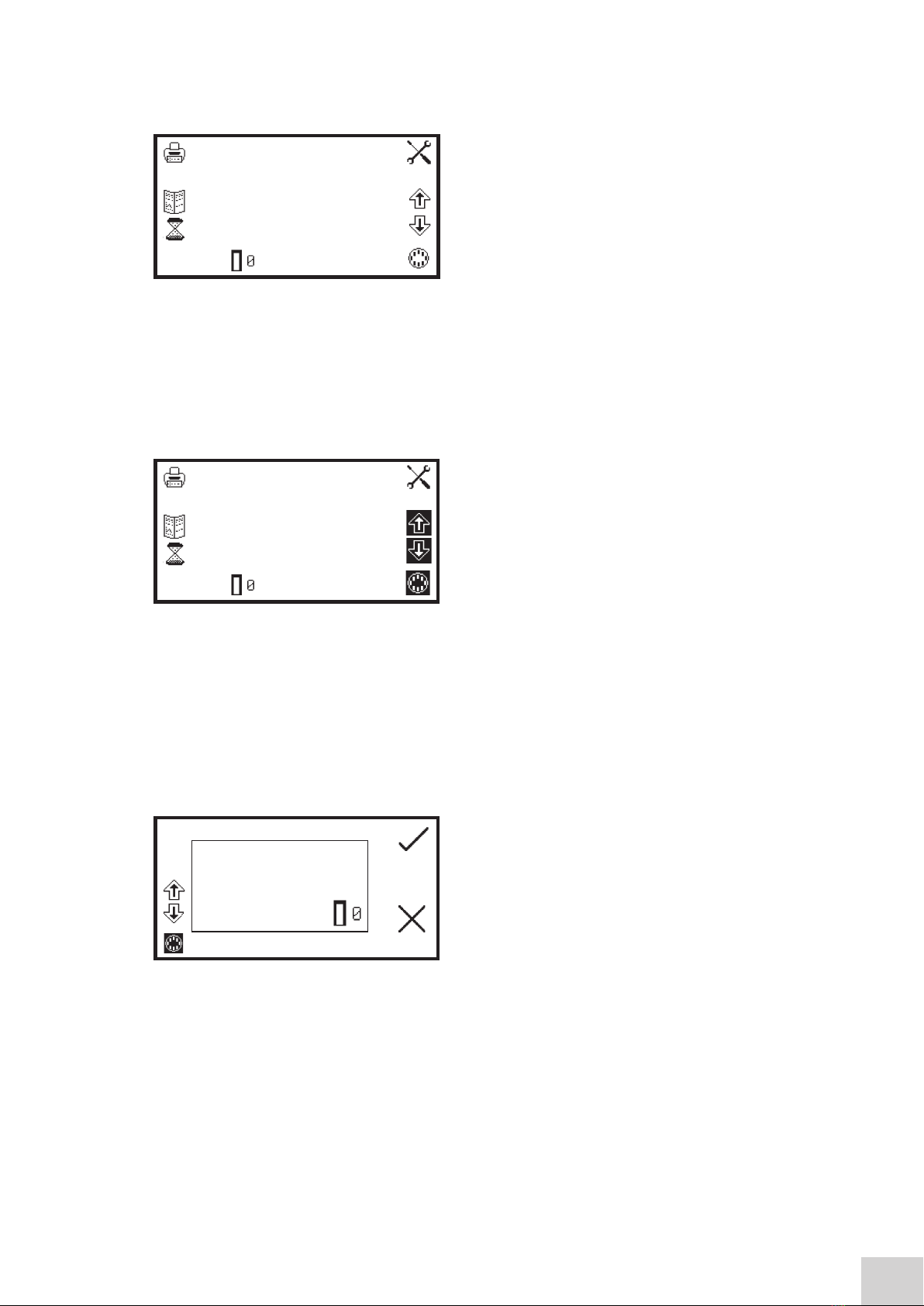
Press the key below the 8 cell turret icon to highlight
the icon and the two arrow icons above. Press the keys
adjacent to the arrow icons to increase or decrease
the current cell position of the turret, until the required
sample position has been selected. Press the key below
the measure sample icon. The instrument will perform a
reading and display the result on the screen.
To measure the next sample select the next turret position and press the key below the measure sample
icon. Repeat this process until all the samples have been measured. To adjust the wavelength press the
key below the 8 cell turret icon and use the arrow icons to adjust the wavelength.
1.3.1.1 Automatic 8 cell turret - supporting creation of a standard curve in quantitation
The 8 cell turret can be used to support creation of a new standard curve in the quantitation measurement
mode.
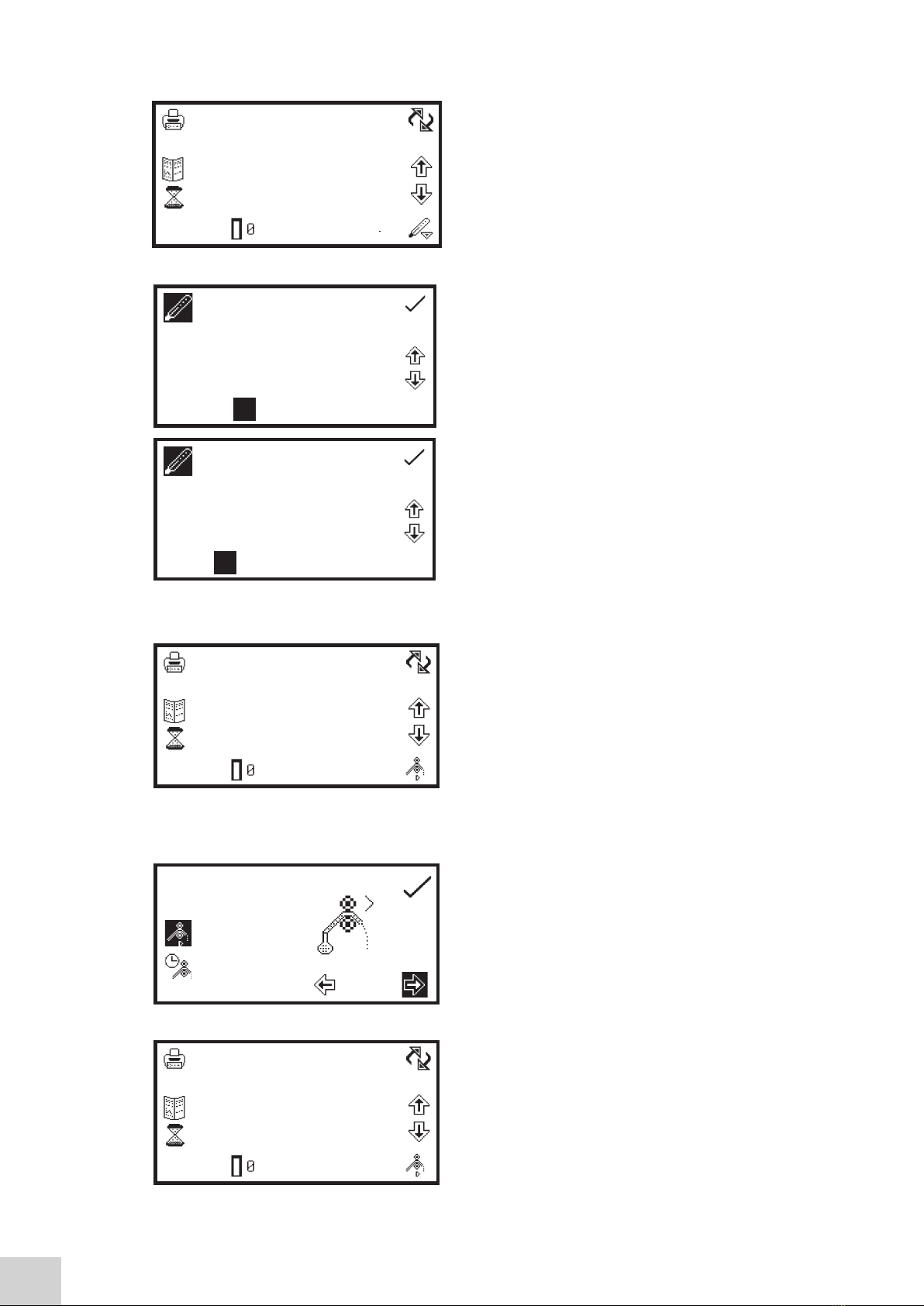
When the standard measurement screen is open the 8
cell turret icon will be displayed in the bottom left hand
corner of the screen. The current cell position is displayed
adjacent to the 8 cell turret icon. The 0 position should
always be used for the zero calibration sample.
To measure the standards using the automatic 8 cell
turret, insert the cuvettes containing the standards into
turret, insert the cuvettes containing the standards into turret positions 1 to 6 (depending on how many
standards needed). Insert the cuvette containing the blank solution into turret position 0. Press the key
adjacent to the tick icon to perform an initial calibration to zero absorbance.
Use the keys adjacent to the arrow icons to increase the turret position, until the required standard
position has been selected. Press the key adjacent to the tick icon to measure the standard. The standard
concentration and photometric value will then be displayed. The standard can be re-measured by pressing
the key adjacent to the back icon.
To measure the next standard select the next turret position and press the key adjacent to tick icon.
Repeat this process until all the standards have been measured.
0.000
0.000
500
09:02 0
ppm
ABS
nm
0.000
0.000
500
09:02 0
ppm
ABS
nm
0.000 ABS
0

1.3.2 Peltier
When the peltier is in use the peltier icon is displayed in
the bottom right hand corner of the screen. The current
temperature is displayed above the set point temperature
adjacent to the peltier icon. Below the peltier icon there
is an arrow icon to indicate if the current temperature is
below or above the set temperature. To adjust the set
point temperature hold the key below the peltier icon
for 2 seconds.
This opens the peltier settings screen. Use the keys at the
bottom of the screen to select the digit to be changed
and use the keys adjacent to the arrow icons to increase
or decrease the number. The temperature can be set
in °C or °F by pressing the key adjacent to the °C icon.
Repeat presses will cycle between °C and °F.
Once the required temperature has been selected press
the key adjacent to the tick icon to save and return to the
expanded operating menu. The peltier will begin to heat
or cool depending on the current temperature.
1.3.3 Sipper pump
When the sipper is in use the sipper pump icon is
displayed in the bottom right hand corner of the screen.
The pump direction is displayed by an arrow icon below
the sipper pump icon. The sipper pump can operate
in manual or timed mode, depending on the option
selected in sipper pump settings. To open the sipper
pump settings hold the key below the sipper pump icon
for 2 seconds.
1.3.3.1 MANUAL SIPPER PUMP SETTINGS
To operate the sipper pump in manual mode press the key
adjacent to the manual sipper icon. Select the preferred
pump direction by pressing the key below the forwards
or backwards arrow icon. Press the key adjacent to the
tick icon to save and return to the expanded operating
menu.
To perform a measurement place the sipper tubing into
the sample and press the key below the sipper pump
icon.
9
.
8006
ºF
0.000
100.0
400
09:02
ABS
%T
nm
0.000
100.0
400
09:02
ABS
%T
nm
19.9
-> 120.5
.
020
ºC
0.000
100.0
400
09:02
ABS
%T
nm

10
Confirmation will be needed to start the sipper pump.
Press the key adjacent to the tick icon to confirm and
start the sipper pump. Press the key adjacent to the cross
icon to cancel and return to the expanded operating
menu.
To stop the sipper pump press the key adjacent to the
stop icon. Ensure that the flow through cuvette contains
enough sample before pressing the key below the
measure sample icon.
1.3.3.2 TIMED SIPPER PUMP SETTINGS
To operate the sipper pump in timed mode press the key
adjacent to the timed sipper pump icon.
Press the key below the calibrate timed sipper icon.
Select the required pump direction by pressing the key
below the forwards or backwards arrow icon. Press
the key adjacent to the tick icon to continue to the next
stage of the calibration sequence.
Insert the inlet tubing into the sample container and
press the key adjacent to the single greater than
icon. The sipper pump will start and the sample will be
pumped through the tubing to the flow through cuvette.
It is possible to skip this setup stage by pressing the key
adjacent to the double greater than icon.
Once the cuvette is full press the key adjacent to the stop
icon to stop the sipper pump. The time taken for sample
uptake is recorded.
0.000
100.0
400
09:02
ABS
%T
nm
0.000
100.0
400
09:02
ABS
%T
nm

11
To fine tune the amount of sample uptake press the key
below the plus or minus icon to increase or decrease the
amount of sample taken up. The recorded time will be
adjusted accordingly. Once the fine tuning is complete, or
if none is required, press the key adjacent to the tick icon
to move to the next stage of the calibration sequence.
This stage allows an air gap to be added to the calibration
sequence. If an air gap is not required press the key below
the 000 icon to set the air gap to zero. If a previously
programmed air gap is to be used press the key adjacent
to the double greater than icon to skip this stage and
retain the current air gap time.
To program an air gap remove the inlet tubing from the sample container and press the key adjacent to
the single greater than icon. The sipper pump will start and air will be pumped through the tubing to
the flow through cell.
Once the required amount of air has been taken up press
the key adjacent to the stop icon. The time taken for air
uptake is recorded.
To fine tune the amount of air uptake press the keys
below the plus or minus icons to increase or decrease
the amount of air taken in. The recorded time will be
adjusted accordingly. Once the fine tuning is complete, or
if none is required, press the key adjacent to the tick icon
to move to the next stage of the calibration sequence.
Once the sample uptake and air gap have been
programmed the preferred disposal of the sample can
be set. There are two options, the sample can either
be sent back to the sample container or it can be sent
to the waste pipe. Press the key below the forward or
backward arrows to select what happens to the sample
after measurement.
If the original pump direction selected was forwards, selecting the forwards direction at this stage will
send the sample to waste and selecting the backwards direction will send the sample back to the sample
container. Once the required direction has been selected press the key adjacent to the tick icon to save
the calibration sequence and return to the expanded operating menu. To exit the sipper calibration
sequence without saving any changes press the back key at any point during the calibration sequence.
000

13
To perform a measurement place the sipper tubing into
the sample and press the key below the sipper pump
icon.
Confirmation will be needed to start the sipper pump.
Press the key adjacent to the cross icon to cancel and
return to the expanded operating menu. Press the key
adjacent to the tick icon to confirm and start the sipper
pump. The pump will run for the previously recorded
sample take up time. Ensure that the flow through
cuvette contains enough sample before pressing the key
below the measure sample icon.
Once the measurement has been performed remove
the tubing from the sample and press the key below
the sipper pump icon to perform the next stage of the
calibration sequence.
Confirmation will be needed to start the sipper pump.
Press the key adjacent to the cross icon to cancel and
return to the expanded operating menu. Press the key
adjacent to the tick icon to confirm and start the sipper
pump. The pump will run for the previously recorded air
gap take up time.
If an air gap of zero was previously selected this screen
will not appear and the calibration sequence will continue
to sample disposal.
Once this stage of the calibration sequence is complete
press the key below the sipper pump icon to dispose
of the sample. Confirmation will be needed to start the
sipper pump. Press the key adjacent to the cross icon to
cancel and return to the expanded operating menu. Press
the key adjacent to the tick icon to confirm and start the
sipper pump. Depending on the disposal route previously
selected the sample will either go to drain or back to the
sample container.
1.3.4 Combined sipper peltier pump
When the combined sipper peltier is in use the sipper
peltier icon is displayed in the bottom right hand corner
of the screen. The current temperature is displayed above
the set point temperature adjacent to the sipper peltier
icon. Adjacent to the peltier icon is an arrow to indicate
if the current temperature is below or above the set
temperature.
0.000
100.0
400
09:02
ABS
%T
nm
0.000
100.0
400
09:02
ABS
%T
nm
0.000
100.0
400
09:02
ABS
%T
nm
0.000
100.0
400
09:02
ABS
%T
nm
0.000
100.0
400
09:02
ABS
%T
nm
20.0
-20.0

The pump direction is displayed by an arrow icon below the sipper peltier icon. The combined sipper
peltier pump combines the functionality of the peltier and sipper pump. To open the sipper peltier
settings hold the key below the sipper peltier icon for 2 seconds.
The settings menu is the same as the sipper pump
settings except for the peltier icon in the top left hand
corner. Pressing the key adjacent to the peltier icon will
open the peltier settings enabling the temperature to be
set. Refer to section 1.3.2 for more details. The sipper
pump can operate in a manual or timed mode. Refer to
section 1.3 for more details.
1.4 SPARES
Part Code
012075
730545
630204
060084
060229
060230
037702
021060
Description of Spare Part
Tungsten halogen lamp
Xenon lamp module
10x10mm path length cuvette holder
Pack of 100 disposable plastic visible wavelength 10x10 cuvettes
Pack of 500 disposable plastic visible wavelength 10x10 cuvettes
Pack of 100 disposable plastic UV wavelength 10x10 cuvettes
Paper roll for printer
24V 65W power supply unit with various plug attachments
14
Order Code
99950-04
99956-12
83070-41
99610-33
83070-30
83070-32
99959-81
99950-56

UK
T: +44 (0) 1480 272279
E: uk.sales@antylia.com
W: coleparmer.co.uk
Germany
T: +49 (0) 9377 92030
E: de.sales@antylia.com
W: coleparmer.de
France
T: +33 (0) 1486 37800
E: fr.s[email protected]om
W: coleparmer.fr
Italy
T: +39 (0) 284349215
W: coleparmer.com
India
T: +9122 61394444
E: info@coleparmer.in
W: coleparmer.in
China
T: +1 847 549 7600
E: sales@antylia.com
W: coleparmer.com
USA
T: +1 847 549 7600
E: sales@antylia.com
W: coleparmer.com
Canada
T: +514 355 6100
E: info@antylia.ca
W: coleparmer.ca
Other
T: +1 847 549 7600
Antylia Scientific Ltd
Beacon Road,
Stone,
Staffordshire,
ST15 0SA,
United Kingdom
Table of contents
Other Cole Parmer Measuring Instrument manuals

Cole Parmer
Cole Parmer Jenway 7415 User manual

Cole Parmer
Cole Parmer 1100 Series User manual

Cole Parmer
Cole Parmer 81150-48 User manual

Cole Parmer
Cole Parmer Stuart SMP11 User manual

Cole Parmer
Cole Parmer 1200 Series User manual

Cole Parmer
Cole Parmer Jenway 76 Series User manual

Cole Parmer
Cole Parmer MB-200-40 User manual

Cole Parmer
Cole Parmer 81150-30 User manual

Cole Parmer
Cole Parmer P100 User manual

Cole Parmer
Cole Parmer Techne FSC400D User manual