COLLARD PROFILMATIC 2000 A User manual

CONSTRUCTEUR DE MATÉRIELS VITICOLES
SPÉCIALISTE DE LA ROGNEUSE A VIGNES
PROFILMATIC® 2000 A
ÉTABLISSEMENT COLLARD –S.A. A DIRECTOIRE ET CONSEIL DE SURVEILLANCE - CAPITAL DE 163.852 EUROS
SIÈGE SOCIAL : 11, RUE JEANNE D’ARC - 51150 BOUZY
TVA INTRACOMMUNAUTAIRE : FR 11341346427 –RCS REIMS B 341 346 427 - SIRET 341 346 427 00014
Agences : OIRY tél : 03.26.57.07.50 SEZANNE tél : 03.26.81.33.88
GUEUX tél : 03.26.89.06.26 RILLY tél : 03.26.03.43.21
Adresse postale : Ets COLLARD S.A - B.P. 1 - 51150 BOUZY France
Tél : (33) 3 26 57 01 12 -- Fax : (33) 3 26 57 09 87
READ INEVITABLY THIS MANUAL
BEFORE USING THE MACHINE
INSTRUCTION MANUAL
CA 1202-C

PL 4693
EC Declaration of conformity for machinery
(Machinery Directive 2006/42/EC , Annexe II ., sub. A)
MANUFACTURER : Ets COLLARD SA
ADDRESS : 11 , rue Jeanne d’arc
51150 Bouzy
France
Name and address of the person authorised to compile the technical :
Name : Yannick COLLARD Address : 11, rue Jeanne d’arc
51150 Bouzy
FRANCE
Herewith we declare that the following equipment :
Type : e
Serial Number : e
Year of construction : e
Is in conformity with the relevant provisions of the Machinery
Directive (2006/42/CE)
Place, date :
Président :
Yannick COLLARD
Signature :

Department of Legal Affairs and Environment
REPLACING PARTS WITH « NON CERTIFIED ORIGINAL PARTS »
WARNING
to equipments users
and to imitated parts manufacturers or sellors
REGARDING LEGAL RISKS – SAFETY - COUNTERFEITING
1. CHANGING OR MOFIFYING COMPONENTS WITH OTHERS THAN THOSE ASSEMBLED
AND RECOMMANDED BY THE MANUFACTURER, IS LIKELY TO QUESTION AGAIN
THE INITIAL SAFETY CONDITIONS OF THE EQUIPMENT.
Any like opération on the equipment will be fully chargeable to he who will have
intervened, and will be likely to challenge the validity of the manufacturer delivered EC
marking.
In this event, the EC déclaration of compliance lapses and THE MANUFACTURER WILL
DISCLAIM HIS REGULATORY LIABILITY.
2. PARTS COUNTERFEITING AND UNFAIR COMPETITION CARRY HEAVY CIVIL AND
CRIMINAL PENALTIES.
Counterfeiting or infringement involves the manufacturer’s, the dealer’s /retailer’s , or even
in some case the imitated parts user’s civil and criminal liability.
Unfair competition involves the manufacturer’s and the « slavish imitations » dealer’s civil
liability, in so far as they take unjustified benefit of this operation, distort usual rules of
competition law by misappropriating the manufacturer’s efforts of design, adjustment,
research of best adequacy and know-how.
The mechanical engineering industries manufacturers
ÞWarn parts manufacturers and dealers, duplicating or selling original parts, about
the legal risk of imitations and unfair competition as for manufacturing and distributing
slavish imitations.
ÞDraw users’ attention to the risk for their EC declaration to lapse in case the safety
conditions originally defined by the equipment manufacturer would be modified, and call
for them not to participate in the intellectual property misappropriation and plundering
which certain dishonest operators indulge in.

PL 4200
PROFILMATICTREE HEDGER
Conditions of use :
This machine is intended exclusively to hedge the excess of vegetation on
the fruit trees.
Any other use is regarded as opposite with the correct use and, thus is
proscribed.
Qualification of the operator :
The machine must be used, maintained and repaired only by people
who know the procedures and safety correspondents.
Responsability of the manufacturer and the user :
Respect the whole of the regulations of installation, operation, adjustment,
maintenance and repair contained in this manual.
Use exclusively spare parts of origin COLLARD and accessories in
conformity according to the recommendations’ COLLARD.
Any modification of your machine and its accessories (mechanics, electric
or hydraulic characteristic) made by yourself or by another person not
competent, can make your machine dangerous.
In the event of damage or wounds, the responsability of the COLLARD
company will be entirely released.

PL 3595
INSTRUCTION MANUAL
1. This manual contains all practical information to make correctly function,
adjust and maintain your machine in safety.
Read attentively and respect all the instructions and recommendations
relating to your safety.
2. Very important symbols
This symbol identifies the significant messages to
respect for your security. When you see this symbol, you
must be attentive with the possible risks of wound. Read
attentively the following message and inform the users.
Await the
complete
immobilization of
all the parts of the
machine before
any intervention.
Read the
instruction manual
and the safety
advices before
starting.
3. Conservation
The instruction manual must be always accompany the machine
permanently.
4. For any information or explanation, please contact us or contact your
usual dealer.

CONTENTS
1) SAFETY INSTRUCTIONS
2) HANDLING AND INSTALLATION
3) OPERATION AND SET UP
4) ADJUSTMENTS
5) MAINTENANCE
6) MECHANICAL SPARE PARTS
7) - DATA SHEET
-HYDRAULIC SYSTEM DIAGRAMS /
SPARE PARTS
8) OPTIONS
These chapters are numbered on the coloured insertion sheets.

SAFETY INSTRUCTIONS
1

PL 4625
SAFETY INSTRUCTIONS :
- Before switching the tractor on ,
- When in transit,
- Whenever the driver leaves the vehicle,
In each of these situations, the blade rotation mechanism must be switched off.
- Before undertaking any cleaning, adjustments, repairs or maintenance activities on
the machine :
oSwitch off the source of hydraulic energy ( tractor motor ).
oLower all cylinders to the base of their stroke so that all loads are in their
lowest position.
oAll the removable protective housing will have to be in place, except when
working on the blades.
- When the tractor driver is not protected by cabin windows, protective glasses must
be worn at all times.
-Before any utilization, control the screws tightening, nut and connection, in
particular on the bracket between the machine and the tractor. Tighten if need be.
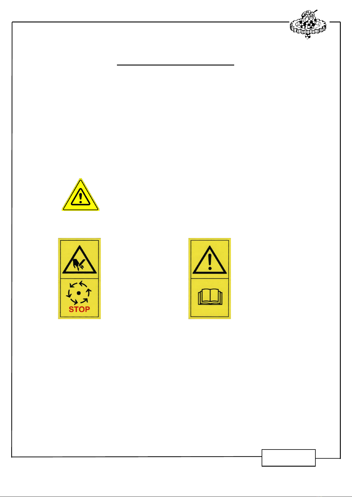
- When setting the blades in motion and at all times during their operation, keep
people well away from the cutting device.
Fore safety’s sake, sound your horn at the beginning of hedging each tree row.
- When leaving a tree row and before maneuvring the tractor at the end of a
hedging, switch off the blade rotation mechanism.
- After each use, the protective housing must be replaced onto the front side of the
blades. They must also be in place during transit on roads or tracks which are
open to traffic.
- No fixed protective parts may be removed from the machine or modified.
- Handling may only be carried out by means of the lifting ring provided for this
purpose.
- When carrying out any work on the blades themselves, requiring their removal or
cleaning, be sure to wear leather gloves, to avoid injury in case of contact with the
cutting edges.
- As soon as any abnormal vibration is felt, stop and inspect the motor, or have it
inspected by the agent until the cause has been identified.

PL 1323
(SAFETY INSTRUCTIONS)
- The blades have been balanced prior to delivery. Normal usage should not affect
the cutting edge. Any blade which receives an impact, becomes deformed or
marked must be replaced.
DO NOT TRY TO RECTIFY THE BLADE.
- Each time the blades are removed, the NYLSTOP nuts must be replaced with new
ones.
-The hydraulic components are adjusted and leaded in factory. Only a dealer
approved COLLARD is authorized to intervene on the adjustments.
-IMPORTANT: the conformity plate, bearing the equipment type and number, must
never be removed from the chassis.
- The operator or the driver should never leave the driver’s cab when the tractor is
moving.
- Nobody is authorized to be in the environment and / or on the trajectory of the
machine.
- Nobody must be installed on the machine.
- Never clean or release the accumulation of vegetation during the machine is
operating. For that, make sure that the engine of the tractor is stopped, and that
the machine is completely immobilized in a vertical position.
- Use, always, protective gloves for any operation.
- During movements on roads, it is imperative to stop the feeding of the electric
controller of the machine (emergency switch engaged); this in order to prevent any
start or any accidental movement of the machine.
- Concerning the machines equipped with protective grates (machines adapted at
the rear mainly), always to take care that the blades of the horizontal cutting
elements are at least at 250 mm (10 inches) minimum inside the lower and upper
edges of the grates.
250 mm mini
(10 inches mini)
250 mm mini
(10 inches mini)
Blades position

HANDLING AND INSTALLATION
2

350
D
Make sure that the
distance between the blade
housing and the front wheel
of the tractor is sufficient.
If this distance
(D)
is to short,
the tires will be in contact
with the cutting elements,
especially during the steering
movements of the wheels).
If this distance cannot
be respected, due to lack of
space, provide a thrust in
order to reduce the stroke of
the steering movement.
Installation
FIXING :
For the fixing of the machine,
present it in front of the tractor at
the desired position.
Make a part of adaptation, which
make it possible to fix the machine
on the tractor.
The height of the frame
above the ground is
350 mm
.
The specifications of your unit in
order to obtain the trimming rates
specified in your order have been
calculated from this position.
This unit is mounted in front of the tractor which is operating in "inter-row".
The load on the front axle is very important, so it is recommended to mount this
machine only on a tractor which is equiped with power steering or hydrostatic steering.
PL 4622

L1
H
L2
A°
Adjust the lenght following the
position of the fixations of the
tractor, then weld the 2 parts
to definitively fix the machine.
Mounting of the reinforcements
- Angle A° upper than 45°
- Lenght L1 as short as possible
- Distance L2 as long as possible (further than the front wheel axle)
- Height H as high as possible
- Check if the tractor is robust sufficiently to
support the weight of
the machine, especially the front part on which the machine is
screwed.
In order to ensure a good mounting of the machine on tractor, the installer
has to mount the provided reinforcements on the machine. Be sure that the
following instructions are absolutely respected :
PL 5001

PL 1389
HANDLING
Transport and installation on tractor to be made with a forklift truck adapted to
the charge by the quills planned for that purpose.
During the lifting, never go under the load and watch to keep away
other persons. Handling has to be carried out by qualified persons,
applying strictly the safety instructions.

PL 1328
NOTE ABOUT THE TYPE OF TRACTOR :
We do not recommend you to use this type of machine on a tractor with
caterpillar tracks. This type of tractor is subject to severe vibrations which can
seriously damage certain parts of the working unit.
However, if you wish to mount the unit on such a tractor, please observe
the following operations :
1) Scrupulously check daily that all parts of the unit, which if loosened
could represent a risk about your safety, are fully tightened.
2) Install a bracket part between the tractor and the machine, able to
withstand the particularly violent forces to which it will be subjected.
3) Reinforce the linkage between the tractor and the machine by using
braces, as provided for on all the anchorage points.

OPERATION AND SET UP
3

PL 3583
SETTING UP
1. MECHANICAL CONTROLS
Make sure, in particular after each adjustment of the cutting
elements, that the blades can rotate without meeting obstacle nor to
touch themselves.
The recommended spacing between the horizontal and vertical
blades is 5 mm.
2. STARTING
Before starting, it is imperative to read and to take into account the
safety instructions.
For the PROFILMATICmachines, one breaking is necessary :
Start the blades approximately 1 hour at 700 to 800 rpm,
then 30 min. at 1000 to 1500 rpm.
3. CONTROL OF RUNNING
The oil temperature should not exceed 70 degrees.

PL 3581
21322132
SETTING UP
In order to get the best output and longest possible years of service from
your COLLARD trimmer, the following operations should be performed prior to
using it for the first time :
Hydraulic checks :
Reference oil : Norm AFNOR NF 48-603 HV (see data sheet)
(example : EQUIVIS ZS 68)
(viscosity at 40°C : 68 mm²/s ; viscosity at 100°C : 11 mm²/s)
Change the oil at least once per year. Make sure that the oil filter is clean.
If necessary, depending on the type of oil filter used, clean or change it.
IMPORTANT : the high technical complexity of the hydraulic components used
on your unit, requires that the oil be perfectly clean.
Parts which suffer damage due to a polluted circuit will
not be covered by a guarantee.
Carefully check the condition of the pump. It must be able to handle the pressure
required by the unit and provide the necessary flow. (See the relevant data
sheet).
The oil flow provided by the pump should not be lower than the flow prescribed
on the data sheet in order to ensure a minimal speed rotation of the blades,
and thus guaranteeing an optimal quality of cut.
Never exceed the maximum level (flow : 60 L/min –15.9 GPM)
If the maximum flow delivered by the tractor exceeds the maximum
acceptable flow by the machine, if this flow is not adjustableand if the
pump of the tractor can not control its flow (reduce its cubic capacity
under the effect of the pressure), it will be necessary to install a device of
regulation imperatively. In case of doubt, contact your dealer.
If the surplus of flow is not controlled, an overheating of the hydraulic
circuit occurs very quickly, then a significant deterioration of the
hydraulic system of the tractor and of the machine.

PL 4485
IMPORTANT
The operation of a hydraulic circuit generally causes pollution due to impurities : loose
projections, paint, silica, sealing paste, rubber, resulting from the dismantling and assembly of
pipework and components.
Filtering
element
Ref. 0502 6044
AT THE FIRST OPERATION
After one hour ½ of operation (corresponding to the running period), it is essential to
check the filter and to service it in order to eliminate pollution and to ensure that none remains
in suspension.
- PRIOR TO DISMANTLING : Clean the module and the area surrounding the
filter plug to avoid dirt entering the filter during servicing.
- Using an appropriate tool, disconnect the hose and remove the filtering element
from the hydraulic block.
- Remove the filtering element by unscrewing the top closing part.
- Soak the filtering element in a container of detergent : gasoline, diesel or benzene
for approximately 5 minutes to decompose particles loaded with oil.
- Blow compressed air through the porous element from the inside to the outside.
- Dry the filtering element.
-Reassemble the filtering element on the hydraulic system. Be carefull to each
joint. Screw the top closing part. Do not force. Clamping torque : 5 N.m.
-Reassemble the complete filter on the block and connect the hose.
SUBSEQUENT USE
Check the state of the porous element at least once during the trimming season. It is
vital that the unit be cleaned before the trimmer is put away (see the higher described
procedure).
IMPORTANT : In all cases, the filter element will be changed every 2 years for a normal
use, and every year in case of an intensive use.
In the event of shock or deterioration, the filter element will have to be
replaced.

PL 3592
CAS PROBABLE CAUSE CHECKS - REMEDIES
1
Calibration of pressure
relief valves too low (or
impurity on the valve
seat)
Increase pressure to the
recommended value or clean unit
2
Motor is worn out or
deteriorated, too much
internal play
Check the oil flow on the drainage. If
the flow is too high, change the
motor, clean the hydraulic circuit,
change the filters
3Pump is worn out
Check the increase in pressure on
the pump or change the pump if
necessary
4Filter clogged Check the filter, change if necessary
5
Type of oil is not suitable
for the trimmer (too liquid
at hig temperature)
Check the oil and change if
necessary for a suitable type
6Motor or pump worn out See cases 2 or 3
7
Calibration of pressure
relief valves too low
Increase pressure to the
recommended value or clean
8
Oil not suitable (viscosity
too high at low
temperature)
Check the oil and change if
necessary for a suitable type
9Oil tank is too small
Change to a higher capacity relative
to the flow of the pump
10 Flow is too heavy
Compare the maximum oil flow of
the pump of the tractor with the
maximum oil flow acceptable by the
machine. Contact your dealer for
more informations.
11
Type of oil is not suitable
(viscosity too high)
Change to a suitable oil
12
The oil is being reduced
inside pressure relief
valve
Regulate pressure in the pressure
relief valve to the recommended
level
13
Clogging of the filter
element
Change the cartridge
Note : The interventions on the hydraulic system must be done by approved techniciens,
except for the change of the cartridge filter.
PROBLEMS WHICH MAY OCCUR AFTER SWITCHING ON THE UNIT
ANOMALY
The blades rotate too
slowly, in spite of a good
output control but speed
increases proportionally
at the temperature
The blades rotate normally
at cold temperature, but
slow down when the
temperature is stabilized
The blades rotate too
slowly, even though the
oil flow corresponds to
recommendations and
even after several
minutes of operation
The temperature
of the circuit is
too high ( > 70°C )

ADJUSTMENTS
4
Table of contents