Buhler FK308 Product manual


8” & 10” Unloading Auger
TABLE OF CONTENTS
DESCRIPTION PAGE
WARRANTY................................................................ 1
INTRODUCTION ......................................................... 2
SAFETY....................................................................... 3
Safety ..................................................................... 3
General Safety ....................................................... 4
Start Up Safety ....................................................... 4
Operation Safety .................................................... 4
Transport Safety..................................................... 5
Service and Maintenance Safety............................ 5
Storage Safety........................................................ 5
Safety Signs ........................................................... 5
Safety Sign Installation ........................................... 6
ASSEMBLY................................................................. 7
Assembly Instructions............................................. 7
OPERATION ............................................................... 8
Operating Instructions ............................................ 8
Theory of Operation................................................ 9
MAINTENANCE .......................................................... 10
Bolt Torque............................................................. 10
PARTS DRAWINGS.................................................... 11
Unloading Auger Drawing....................................... 11
Unloading Auger Drawing Parts List....................... 12
Electric Motor Drive Unloading Auger Drawing ...... 14
Electric Motor Drive Unloading Auger Parts List..... 15
SHIPPING KIT AND BUNDLE NUMBERS ................. 17

8” & 10” Unloading Auger
1
WARRANTY POLICY
Buhler Manufacturing products are warranted for a period of twelve (12) months (90 days for
commercial application) from original date of purchase, by original purchaser, to be free from
defects in material and workmanship under correct, normal agricultural use and proper
applications.
Buhler Manufacturing’s obligations under this warranty shall be limited to the repair or
exchange, at Buhler Manufacturing’s option, of any Buhler Manufacturing product or part which
proves to be defective as provided. Buhler Manufacturing reserves the right to either inspect
the product at the buyer’s location or have it returned to the factory for inspection.
The above warranty does not extend to goods damaged or subject to accident, abuse or misuse
after shipment from Buhler Manufacturing’s factory, nor to goods altered or repaired by anyone
other than an authorized Buhler Manufacturing representative.
Buhler Manufacturing makes no Express Warranties other than those, which are specifically
described. Any description of goods, including any references and specifications in catalogues,
circulars and other written material published, is for the sole purpose of identifying goods and
shall conform to such descriptions. Any sample or model is for illustrative purposes only and
does not create an Express Warranty that the goods conform to sample or model shown.
The purchaser is solely responsible for determining suitability of goods sold. This warranty is
expressly in lieu of all other warranties expressed or implied. Buhler Manufacturing will in no
event be liable for any incidental or consequential damages whatsoever. Nor for any sum in
excess of the price received for the goods for which liability is claimed.
WARRANTY CLAIMS:
Warranty requests must be prepared on Buhler Manufacturing Warranty Claim Forms with all
requested information properly completed. Warranty Claims must be submitted within a thirty
(30) day period from date of failure repair.
WARRANTY LABOR:
Any labor subject to warranty must be authorized by Buhler Manufacturing. The labor rate for
replacing defective parts, where applicable, will be credited at 100% of the dealer’s posted shop
rate. Defective parts will receive an extra 10% discount to assist with freight or other incidental
costs.
GOVERNMENT LEGISLATION:
Warranty terms and conditions are subject to Provincial or State legislation.
IMPORTANT FACTS:
Buckets and Bucket Tines Carry No Warranty
Bent Spears Carry No Warranty
Snowblower Fan Shafts Carry No Warranty
Mower Blades Carry No Warranty
Portable Auger Parts Have Two (2) Year Warranty
Loader Parts Have Two (2) Year Warranty
IMPORTANT NOTE: This warranty does not apply to rentals

8” & 10” Unloading Auger
2
INTRODUCTION
The Buhler Farm King 8” and 10” unloading augers reach where normal portable augers
can’t. They feature a loading hopper that fits right under hopper bottom bins and
hopper trailers for fast and easy access. With a hopper that is almost four feet square
and your choice of 8” or 10” diameter tubing, the Buhler Farm King unloading augers
transfer your grains and oilseeds much faster than conventional utility augers. The
weight is evenly distributed on either side of the pivot wheels. Because the unit is so
well balanced, it can be easily positioned by one person with a minimum of effort.
A hinged cleanout gate in the bottom of the hopper makes thorough cleaning simple.
You do not need to worry about spoiled grain or rusting that can occur when grain is left
sitting.
Buhler Farm King gives you a choice between hydraulic or electric motor. Adjustable
discharge height lets you position the auger to fit the job. Now, you can unload hopper
bins and trailers more quickly and easily than ever before.
Keep this manual handy for frequent reference. All new operators or owners must
review the manual before using the equipment and at least annually thereafter. Contact
your Buhler Dealer if you need assistance, information, or additional copies of the
manual. Visit our website at www.buhler.com for a complete list of dealers in your area.
The directions left, right, front and rear, as mentioned throughout this manual, are as
seen facing in the direction of travel of the implement.

8” & 10” Unloading Auger
3
SAFETY
Remember, YOU are the key to safety. Good safety practices not only protect you, but
also the people around you. Make these practices a working part of your safety
program. Be certain that everyone operating this equipment is familiar with the
recommended operating and maintenance procedures and follows all the safety
precautions. Most accidents can be prevented. Do not risk injury or death by ignoring
good safety practices.
The alert symbol is used throughout this manual. It indicates attention is required and
identifies hazards. Follow the recommended precautions.
The safety alert symbol means…
ATTENTION! BECOME ALERT! YOUR SAFETY IS INVOLVED!
CAUTION
The caution symbol indicates a potentially hazardous situation that, if not avoided, may
result in minor or moderate injury. It may also be used to alert against unsafe practices.
WARNING
The Warning Symbol indicates a potentially hazardous situation that, if not avoided,
could result in death or serious injury, and includes hazards that are exposed when
guards are removed. It may also be used to alert against unsafe practices.
DANGER
The Danger Symbol indicates an imminently hazardous situation that, if not avoided will
result in death or serious injury. This signal word is to be limited to the most extreme
situations, typically for machine components that, for functional purposes, cannot be
guarded.

8” & 10” Unloading Auger
4
GENERAL SAFETY INSTRUCTIONS
Have a first-aid kit available for use and know how to use it.
Have a fire extinguisher available, stored in a highly visible location, and know how to
use it.
Wear appropriate protective gear. This list may include but is not limited to:
- Hard hat
- Protective shoes with slip resistant soles
- Protective glasses or goggles
- Heavy gloves
- Wet weather gear
- Hearing protection
- Respirator or filter mask
Read and understand the Operator’s Manual and all safety signs before operating,
servicing, adjusting, repairing, or unplugging the equipment.
Do not attempt any unauthorized modifications to your Buhler product as this could
affect function or safety, and could affect the life of the equipment.
Inspect and clean the working area before operating.
Keep hands, feet, clothing, and hair away from moving parts.
Ensure bystanders are clear of the area before operating.
START-UP SAFETY
Do not let inexperienced operators or children run this equipment.
Place all tractor and machine controls in neutral before starting.
Operate only with ROPS and seatbelt equipped tractors.
Do not operate inside a building unless there is adequate ventilation.
Ensure all shields are in place and in good condition before operating.
Make certain electric motors are grounded.
OPERATION SAFETY
Do not permit riders.
Do not wear loose fitting clothing during operation.
Do not allow anyone other than the operator close to the Auger when in operation.

8” & 10” Unloading Auger
5
TRANSPORT SAFETY
Review Transport Safety instructions in tractor manual before moving.
Check with local authorities regarding transport on public roads. Obey all applicable
laws and regulations.
Make sure the SMV (Slow Moving Vehicle) emblem and all the lights and reflectors that
are required by the local highway and transport authorities are in place, are clean, and
can be seen clearly by all overtaking and oncoming traffic.
Take extreme caution in maneuvering on or around tight corners so as not to catch the
end of the auger on trees, buildings, power lines, etc.
When moving the auger on the road, always use a red flag, or if absolutely necessary to
move at night, accessory lights for adequate warning to operators of other vehicles.
Always travel at a safe speed.
Inflate transport tires to recommended pressure.
SERVICE AND MAINTENANCE SAFETY
Stop engine, set brake, remove ignition key, and wait for all moving parts to stop before
servicing, adjusting, repairing, or unplugging.
Support the equipment with blocks or safety stands before working beneath it.
Follow good shop practices including
- Keep service area clean and dry
- Be sure electrical outlets and tools are properly grounded
- Use adequate light for the job
Use only tools, jacks, and hoists of sufficient capacity for the job.
Replace and secure all shields removed during servicing before operating.
Use heavy leather gloves to handle sharp objects.
Check hydraulics regularly for leaks. Use cardboard to look for leaks, and use hand and
eye protection.
Relieve pressure on hydraulic system before repairing or adjusting.
Failure to follow proper procedures when mounting a tire on a wheel or rim can produce
an explosion, which may result in serious injury or death.
STORAGE SAFETY
Store the unit in an area away from human activity.
Do not permit children to play on or around the stored machine.
Support the frame on stands and blocks to provide a secure base.
SAFETY SIGNS
The following illustration shows the approximate location and detail of safety signs.
Keep all safety signs clean and legible and replace any that are damaged or missing.
When original parts are replaced, any safety signs affixed to those parts should be
replaced as well. Replacement safety signs are available from your local dealer.

8” & 10” Unloading Auger
6
SAFETY SIGN INSTALLATION
To install safety signs, ensure the installation area is clean and dry. Decide on the
exact position before you remove the backing paper. Remove the smallest portion of
the split backing paper and align over the specified area. Carefully press in place.
Slowly peel back the remaining paper and smooth the remaining portion in place. Small
air pockets can be pierced with a pin and smoothed out.
#961015 #961016
Replace safety signs immediately should they become damaged, torn or illegible.
Obtain replacements from your authorized dealer using the part numbers shown.

8” & 10” Unloading Auger
7
ASSEMBLY INSTRUCTIONS
1. Bolt the hopper and tube together using six ½” x 1 ¼” hex bolts, lock
washers, and hex nuts on the 10”. Use 3/8" x 1" hex bolts on the 8”.
2. Bolt the stand to the tube using four ½” x 1 ¼” hex bolts, lockwashers, and
hex nuts. The stands have a high and low position (see chart).
2. Bolt the rubber strips around the hopper using the metal strips and plates
supplied. Use ¼” x ¾” hex bolts, lockwashers, and hex nuts.
3. Hydraulic only – attach the two ½” x 18” hydraulic hoses from the valve
to the hydraulic motor.
4. Motor Drive only -
- Assemble motor mount using ¾” nuts.
- Mount 12" pulley on flighting and 3 ½” pulley on motor. Use a 1725 rpm
motor with 3 to 5hp and a B-54 V-belt.
- Mount belt guard using ¼” x 1" hex bolts and ¼” hex nuts.

8” & 10” Unloading Auger
8
OPERATING INSTRUCTIONS
When operating an auger for the first time when new, or at the beginning of a season,
run only partially full until flighting becomes polished. Also check the spout and hopper
for bird nests or other obstructions before starting the auger.
The set screws in the universal joint joining the hopper and tube flighting must be
checked regularly and tightened if necessary. The brass bushing in the bushing holder
inside the hopper is another part that should be checked regularly and replaced if
necessary.
To check or service the universal joint or the brass bushing holder, remove the cover at
the front of the hopper.
Hydraulic Unloading Auger:
Approximate hydraulic requirements are:
12 gallons per minute pump capacity
1200-1400 psi hydraulic pressure
Auger rpm and capacity are adjusted using the flow control valve.
Motor Drive Unloading Auger:
Power requirement is from 3 to 5 horsepower electric motor 1725 rpm. Use the 12 inch
double pulley supplied on the auger. The 3 ½” double pulley with b-grooves and two B-
54 V-belts must be supplied by the customer. A 3 horsepower should be sufficient for
the 8”.
Both kinds of unloading auger have wheel stands with adjustable height. Specifications
are given on a chart included in the manual.

8” & 10” Unloading Auger
9
THEORY OF OPERATION
MAINTENANCE AND STORAGE
Lubricate the universal joint about every five hours and check to see that the set screws
in the universal joint are tight.
Clean the auger thoroughly after using as dirt draws moisture and causes metal to rust.
Store in a dry place if possible.
Remove belts and store in a cool dry place if auger is to be left outdoors.
At this time check all parts for wear and order replacement parts from your nearest
dealer.
When taking the auger out of storage, check inlet and outlet ends for obstructions and
check all bolts and set screws before using the auger.
ALERT: When replacing bearings or tightening a loose bearing collar, always
tighten collar, always tighten collar in the direction of shaft rotation
using a center punch or a similar tool.
Recommended tire pressure is 32 psi.

8” & 10” Unloading Auger
10
BOLT TORQUE

8” & 10” Unloading Auger
11
8” & 10” HYDRAULIC UNLOADING AUGER

8” & 10” Unloading Auger
12
WHEN ORDERING PARTS
Always give your dealer the Model, Color and Serial Number of your machine to assist
him in ordering and obtaining the correct parts. Use the exploded view and tabular
listing of the area of interest to exactly identify the required part.
8'' & 10'' HYDRAULIC UNLOADING AUGER
ITEM PART # DESCRIPTION
1 960184 Tube Weldment (8'')
960448 Tube Weldment (10'')
2 960325 Hopper Weldment (8'')
960440 Hopper Weldment (10'')
3 960270 Tube Flighting (8'')
960442 Tube Flighting (10'')
4 960268 Hopper Flighting (8'')
960233 Hopper Flighting (10'')
5 960241 Universal Joint (1140)
6 960326 Bushing Holder w/ Bushing
7 960185 Axle Assembly (8'')
960450 Axle Assembly (10'')
8 960048 2 1/2'' x 8'' Wheel
9 961627 1'' Bearing
10 973511 1'' Bearing Flange Set
11 960153 Hopper Rubber Edging (4'' x 90'')
12 960154 Rubber Connector Plate (2'' x 3'')
13 960155 Side Rubber Reinforcement (1'' x 45 1/2'')
14 960156 End Rubber Reinforcement (1'' x 16'')
15 973613 16'' x 4.8'' Wheel W/ Tire
973655 Wheel Only (8'' x 2.5'')
973656 Tire W/ Tube (4.80/4.00-8)
16 960186 Hydraulic End Plate (8'')
960320 Hydraulic End Plate (10'')
17 908432 Hydraulic Motor (103-1614) (3/8'' Geroler) - 8''
907344 Hydraulic Motor (103-1003) (1/2'' Geroler) - 10''
18 960050 Flow Control Valve W/ Bushing
19 964645 1/2'' x 18'' Hyd. Hose (One Swivel End)
(Bolt Ends 1/2'' NPT)
20 964738 1/2'' x 90 Deg. Street Elbow
21 964740 1/2'' x 1/2'' x 1/2'' Tee
22 960051 1/2'' Close Nipple
23 960238 Splash Guard
24 960239 Splash Guard Clips

8” & 10” Unloading Auger
13
25 960237 Box Cover 6 3/4" x 14 1/4" - 8" Una
908344 Box Cover 6 1/2" x 16" - 10" Una
26 963026 1/4'' Sq. x 1 1/2'' Key (8")
960177 1/4" x 1 1/4" Key (10")
27 967460 3/8'' x 3/4'' Sq. Hd. Set Screw (SER)
28 86170 3/8" x 1" Hex Bolt (8")
81620 1/2'' x 1 1/4'' Hex Bolt (10")
29 81593 3/8" Lock Washer (8")
81637 1/2'' Lock Washer (10")
30 81592 3/8" Hex Nut (8")
81636 1/2'' Hex Nut (10")
31 9812433 3/16'' x 1 1/2'' Cotter Pin
32 84522 1'' I.D. Flat Washer (S.A.E.)
33 967193 1/4'' x 2 1/2'' Hex Bolt
34 81545 1/4'' Lock Washer
35 81544 1/4'' Hex Nut
36 84072 3/8'' x 3/4'' Hex Bolt
37 81593 3/8'' Lock Washer
38 81549 5/16'' x 3/4'' Hex Bolt
39 81569 5/16'' Lock Washer
40 81568 5/16'' Hex Nut
41 81597 7/16'' x 1'' Hex Bolt
42 84041 7/16'' S.A.E. Flat Washer
43 81615 7/16'' Lock Washer
44 81614 7/16'' Hex Nut
45 81671 5/8'' x 4'' Hex Bolt
46 812482 5/8'' Lock Nut
47 985639 3/8'' X 1/2'' Socket Set Screw
48 81525 1/4'' x 3/4'' Hex Bolt
49 81545 1/4'' Lock Washer
50 81544 1/4'' Hex Nut
51 960461 Brass Bushing Only
52 960236 Wheel Bracket
53 9812426 1/4'' x 1 3/4'' Roll Pin
54 86170 3/8'' x 1'' Hex Bolt
55 81592 3/8'' Hex Nut
56 960400 Wheel Bearing Only
57 967158 3/4'' --> 1/2'' Reducer Bushings
58 81527 1/4" x 1" Hex Bolt
59 81546 1/4" B.S. Flat Washer

8” & 10” Unloading Auger
14
8” & 10” ELECTRIC MOTOR DRIVE UNLOADING AUGER

8” & 10” Unloading Auger
15
8'' & 10'' ELECTRIC MOTOR DRIVE UNLOADING AUGER
ITEM PART # DESCRIPTION
1 960187 Tube Weldment (8'')
960462 Tube Weldment (10'')
2 960325 Hopper Weldment (8'')
960440 Hopper Weldment (10'')
3 960188 Tube Flighting (8'')
960463 Tube Flighting (10'')
4 960268 Hopper Flighting (8'')
960233 Hopper Flighting (10'')
5 960241 Universal Joint (1140)
6 960326 Bushing Holder W/ Bushing
7 960461 Bushing Only
8 960189 Axle Assembly (8'')
960316 Axle Assembly (10'')
9 960048 2 1/2'' x 8'' Wheel
10 961627 1'' Bearing
11 973511 1'' Bearing Flange
12 960153 Hopper Rubber Edging (4'' x 90'')
13 960154 Rubber Connector Plate (2'' x 3'')
14 960155 Side Rubber Reinforced (1'' x 45 1/2'')
15 960156 End Rubber Reinforced (1'' x 16'')
16 973613 16'' x 4.8'' Wheel W/ Tire
973655 Wheel Only (8" x 2.5")
973656 Tire W/ Tube (4.80/4.00-8)
17 86170 3/8'' x 1'' Hex Bolt
18 960400 Wheel Bearing Only
19 960238 Splash Guard
20 960239 Splash Guard Clips
21 960237 Box Cover 6 3/4" x 14 1/4" - 8" Una
908344 Box Cover 6 1/2" x 16" - 10" Una
22 960190 Motor Drive End Plate (8'')
960321 Motor Drive End Plate (10'')
23 963707 Motor Mount Assembly
24 960464 Motor Mount Support
25 961567 12'' Double Pulley
26 F1307 Belt Guard
27 968811 1/4'' Sq. x 2'' Key
28 81213 3/8'' x 1'' Sq. Hd. Set Screw
29 81700 3/4'' Hex Nut
30 81549 5/16'' x 3/4'' Hex Bolt
31 81569 5/16'' Lock Washer

8” & 10” Unloading Auger
16
32 81568 5/16'' Hex Nut
33 86171 3/8'' x 1 1/4'' Hex Bolt
34 81593 3/8'' Lock Washer
35 81592 3/8'' Hex Nut
36 86170 3/8" x 1" Hex Bolt (8")
81620 1/2'' x 1 1/4'' Hex Bolt (10")
37 81593 3/8" Lock Washer (8")
81637 1/2'' Lock Washer (10")
38 81592 3/8" Hex Nut (8")
81636 1/2'' Hex Nut (10")
39 81527 1/4'' x 1'' Hex Bolt
40 81544 1/4'' Hex Nut
41 84522 1'' I.D. Flat Washer (S.A.E.)
42 9812433 3/16'' x 1 1/2'' Cotter Pin
43 963026 1/4'' Sq. x 1 1/2'' Key (8")
960177 1/4" x 1 1/4" Key (10")
44 9812378 3/8'' x 3/4'' Sq. Hd. Set Screw (SER)
45 81598 7/16'' x 1 1/4'' Hex Bolt
46 84041 7/16'' S.A.E. Flat Washer
47 81615 7/16'' Lock Washer
48 81614 7/16'' Hex Nut
49 81525 1/4'' x 3/4'' Hex Bolt
50 81545 1/4'' Lock Washer
51 81546 1/4'' B.S. Flat Washer
52 81671 5/8'' x 4'' Hex Bolt
53 812482 5/8'' Lock Nut
54 960236 Wheel Bracket
55 9812426 1/4'' x 1 3/4'' Roll Pin

8” & 10” Unloading Auger
17
SHIPPING KIT AND BUNDLE NUMBERS
8” UNLOADING AUGER
The following is a list of Kit Numbers for this product and the Bundle Numbers,
Descriptions, and Quantities for each Kit.
QUANTITY BUNDLE NO. DESCRIPTION
Y810H Hydraulic Unloading Auger
1 F1050 8" x 9' Auger Tube
1 F1051 Carton of Parts
1 F1052 Axle Assembly
1 F7338 Hopper Assembly
Y810E Motor Drive Unloading Auger
1 F1053 8" x 9' Auger Tube
1 F1054 Carton of Parts
1 F1055 Axle Assembly
1 F1307 Belt Guard
1 F7338 Hopper Assembly
10” UNLOADING AUGER
Y1010H Hydraulic Unloading Auger
1 F1011 10" x 9' Auger Tube
1 F9041 Hopper Assembly
1 F1013 Carton of Parts
1 F1014 Axle Assembly
Y1010E Motor Drive Unloading Auger
1 F1015 10" x 9' Auger Tube
1 F9041 Hopper Assembly
1 F1016 Carton of Parts
1 F1017 Axle Assembly
1 F1307 Belt Guard
Table of contents
Other Buhler Farm Equipment manuals

Buhler
Buhler FK370 Product manual

Buhler
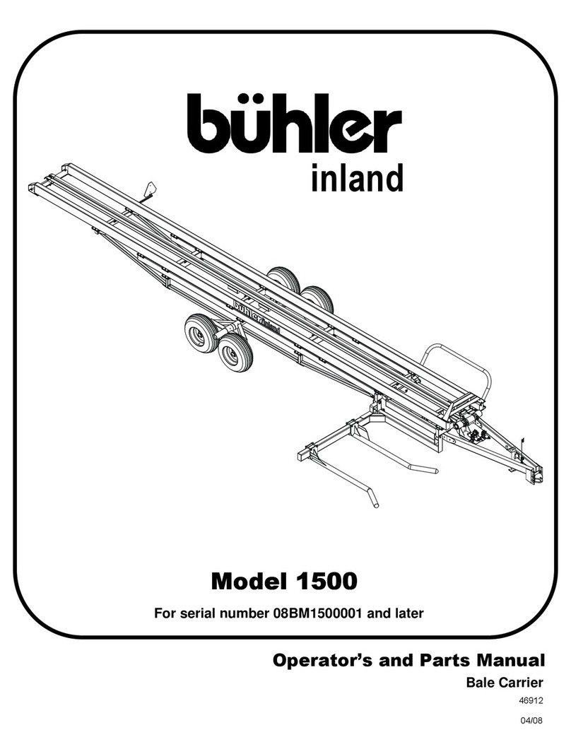
Buhler Round Bale Carrier 1500 Product manual

Buhler
Buhler Swath Roller FK358 Product manual

Buhler
Buhler 480 User manual

Buhler
Buhler Inland 1500 Product manual

Buhler
Buhler inland 4500 Product manual

Buhler
Buhler Farm King Grain Vac Conveyair 6640 Product manual

Buhler
Buhler Genesis II 2145 User manual

Buhler
Buhler 360 User manual
Popular Farm Equipment manuals by other brands

Rauch
Rauch AXIS EMC ISOBUS Original instructions

GREAT PLAINS
GREAT PLAINS MC5109 Max-Chisel Assembly manual

Pottinger
Pottinger TOP 762 C classic Operator's manual

Sulky Burel
Sulky Burel DX ISOBUS Technician's Operating Manual

Malone
Malone Tedd-Air Series Operator's manual

Agrimotor
Agrimotor ROTALUX 52A Series Instructions for use