Veris U3 User manual

Pub# OM20-U3-pH
1-1
U3 EC/OM/pH
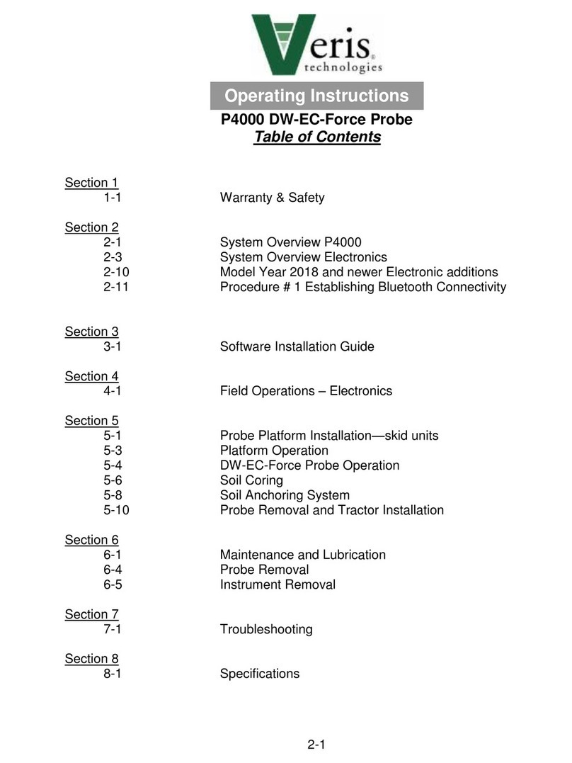
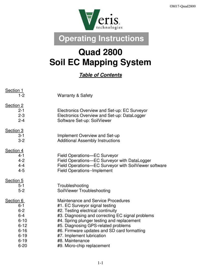
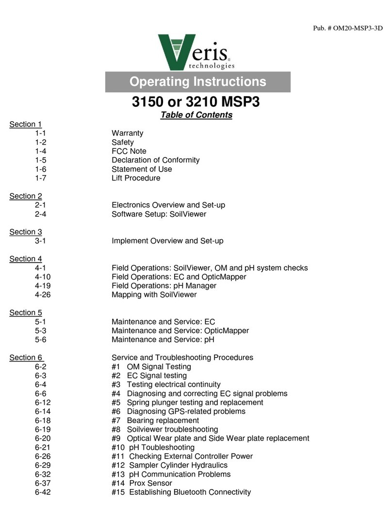
Table of Contents
Section 1
1-2 Warranty
1-3 Safety
Section 2
2-1 Electronics Overview and Set-up: V.Sense Controller
2-6 Software Set-up: SoilViewer
Section 3
3-1 Implement Overview and Set-up
Section 4 SoilViewer and Controller Set-up
4-1 Overview and file naming
4-2 pH Controller overview and settings
4-8 SoilViewer messages
4-9 Optical system check
4-11 pH system check
Section 5 Field Operations
5-1 Implement and EC Settings
5-4 Optical settings
5-6 pH settings
5-9 Winterization and storage
Section 6 Maintenance and Service Procedures
6-1 #1. OM signal testing
6-2 #2. EC signal testing
6-3 #3. Testing electrical continuity
6-5 #4. Diagnosing and correcting EC signal problems
6-11 #5. Spring plunger testing and replacement
6-13 #6. Diagnosing GPS-related problems
6-14 #7. Implement lubrication
6-16 #8. Bearing replacement
6-17 #9. Optical Wear plate replacement
6-18 #10. SoilViewer Troubleshooting
6-19 #11 Establishing Bluetooth connection to V.Sense Controller
6-21 #12 U Series pH troubleshooting
Operating Instructions

Pub# OM20-U3-pH
1-2
U3-EC/OM/pH
SoilViewer Version 2.79 or Above
Section 1
Warranty
Veris Technologies warrants this product to be free of defects in materials and workmanship for a period of
one (1) year from the date of delivery to the purchaser. Veris Technologies will repair or replace any product
returned to Salina, Kansas, which appears upon inspection to be defective in materials or workmanship.
Veris Technologies shall have no obligation under this warranty for the cost of labor, down-time,
transportation charges, or for the repair or replacement of any product that has been misused, carelessly
handled, modified, or altered.
ALL OTHER WARRANTIES OF ANY KIND, WHETHER EXPRESSED OR IMPLIED, INCLUDING BUT
NOT LIMITED TO ANY IMPLIED WARRANTY OF MERCHANTABILITY OR OF FITNESS FOR A
PARTICULAR PURPOSE AND ALL CLAIMS FOR CONSEQUENTIAL DAMAGES, ARE SPECIFICALLY
DISCLAIMED AND EXCLUDED.
Safety

Pub# OM20-U3-pH
1-3
Important! Read the following SAFETY PROCEDURES before operating the Veris system:
• Read and understand all instructions on safety decals
• Escaping fluid under pressure can penetrate the skin causing serious injury. Avoid the hazard by
relieving pressure before disconnecting hydraulic lines. Use a piece of paper or card-board, NOT BODY
PARTS, to check for suspected leaks.
• Wear protective gloves and safety glasses or goggles when working with hydraulic and high-pressure
wash systems.
• If an accident occurs, see a doctor immediately. Any fluid injected into the skin must be surgically removed
within a few hours or gangrene may result.
• Pinch point hazard: to prevent injury, stand clear when raising or lowering any part of the Veris implement.
• Install all transport locks before transporting or working underneath.
• Detach and store implements in an area where children normally do not play. Secure implement by using
blocks and supports.
• Read Operations Manual before operating machine
• Review safety instructions with operators before operating machine and at least annually
• Never stand on or use tire as a step
• Do not tow the implement on public roads without the road-kit light package, or without the proper safety
equipment and licensing as required by your State Department of Transportation. Always use safety chain.
• Riders obstruct the operator’s view. They could be struck by foreign objects or thrown from the
machine.
• Never allow children to operate equipment.
• To prevent possible electrical shock, or damage to the instrument, do not connect to any power source
greater than twelve (12) volts DC.
• Do not grease or oil implement while it is in operation.
• Disk edges are sharp. Be careful when working in this area.
• Disconnect battery ground cable (-) before servicing or adjusting electrical systems or before welding on
implement.
• Remove buildup of mud, oil or debris.
• Be very careful when mapping stubble fields with a gasoline engine pickup. Be prepared if a fire starts.
• Keep a first aid kit and fire extinguisher handy.

Pub# OM20-U3-pH
2-1
Section 2
Electronics Overview and Set-up
The U3 electronics kit includes the items shown below
Keep all diagnostics and operations manual with system when mapping.
The supplied GPS (Figure 2a or 2b) is configured to
operate with the U3 electronics. Note: V.Sense
controllers manufactured before 9/01/2016 are equipped
with the external GPS shown in Figure 2a.
The use of any other GPS requires the correct settings. The
GPS needs to output only two NEMA strings(GGA and VTG
OR RMC). The system will not run with more than two
strings. The strings need to output at 4800 baud and 1Hz
refresh rate
U3000
Implement
test box
SoilViewer
Software
OM Reference
Block
USB Serial
Adapter
EC Test Load
OM Test Load
Figure 1
Figure 2a
Note: V.SENSE controllers manufactured after
9/01/2016 contain an internal Garmin 15x GPS. No
external GPS (Figure 2a) is provided on these units.
The controller will automatically give preference to any
external GPS source connected to the GPS input. If no
external connection is recognized, the controller will
automatically source the internal GPS for signal.
Figure 2b

Pub# OM20-U3-pH
2-2
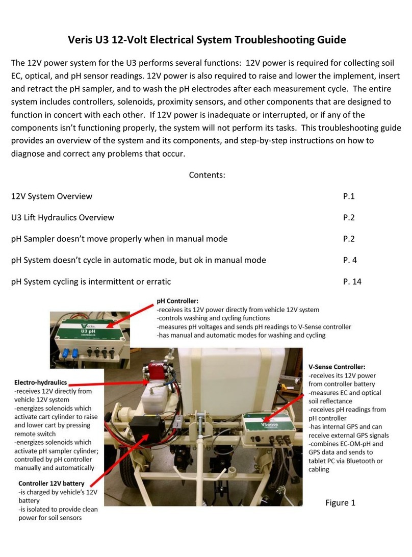
The V.Sense Controller is mounted on the implement, and can remain on the implement due to
weatherproofing. Unless opened by operator and lid seal is damaged. If the implement is stored outside for
long-term storage, remove Controller and store it indoors.
Figure 3 U3000 Figure 4 V.Sense Controller
Figure 5 V.Sense Controller (rear)
Figure 6 V.Sense Controller (front)
pH Controller
On/Off
Turns power to
V.Sense
Controller
On/Off
3A Fuse
OM Comm
Serial communication to PC,
and GPS input
12V Power
Power cord shipped with the unit that
connects to the vehicle’s battery
Power Indicator
Indicates when power to
the controller is on
Optic Power
Delivers power to
Optical sensor with
supplied cable
EC Signal
Bluetooth
Antenna
Depth Sensor
U3 pH Comm port

Pub# OM20-U3-pH
2-3
The pH controller is mounted on the rear of the implement and controls the functions on the
pH sampling system.
Figure 7
Backup battery and voltage isolator
These components are connected to the V.Sense controller to maintain 12 volts to the controller during
cycling of the electro-hydraulic pump. This should require no service, other than periodically testing to see
that it is maintaining a full 12 volt charge.
Figure 8
On/off
switch
Man/Auto
switch
pH
electrode
ports
Manual
sampler
Up/down
Manual
wash switch
Isolator
12V battery

Pub# OM20-U3-pH
2-4
Electronic Configurations
The U3 platform is comprised of two controllers: V.Sense and U3 pH The V.Sense controller generates the
EC and Optical signals, and communicates with the U3 pH controller, and the PC (SoilViewer software)
either via serial or Bluetooth. The SoilViewer software reads the status of the GPS and U3 pH controller
signal inputs (ex. up or down proximity sensors), and initiates the pH cycling when the cycle criteria are met.
Figure 9

Pub# OM20-U3-pH
2-5
Software Setup
Note: For computers outside the United States of America, please make the following change to the
computer’s regional settings before installing the Veris SoilViewer Software.
Step 1: Open control panel and double click on Region
Step 2: Click on Additional Settings, the following screen will appear. The Decimal symbol needs to be a
“.” while the Digit grouping symbol needs to be a “,”. The will ensure proper operation of the software.
Once the changes have been made click OK and proceed with installation.
Figure 10
Figure 11
Open Veris flash drive and double click
on setup.exe to start the installation.
Click Next to continue through
installation

Pub# OM20-U3-pH
2-6
Figure 12
Figures 13
Figure 14
Next two license
agreements will need to be
accepted before continuing.
The installer will install
all necessary
components.
Click Next to continue through
installation

Pub# OM20-U3-pH
2-7
Figure 15
Figure 16
Figure 17
Click Next to install the USB drivers.
Click Next to continue through
installation
Click Finish to complete the
installation of SoilViewer.

Pub# OM20-U3-pH
3-1
Section 3
Implement Overview and Set-up
If the unit is crated, some assembly may be required. To do so, please take precautions to ensure that the
framework is properly supported to ensure safety. Below in Figure 1 are the key components of the unit.
Figure 1
Figure 2
EC
Coulters
pH Wash
tank
pH sampler
optical row
unit
Electro-
hydraulics
pH
Controller
Electro-
Hydraulics
V.Sense
controller
Backup
battery
and
isolator

Pub# OM20-U3-pH
3-2
Connection to Power unit
The U3 is easily connected to a UTV or small tractor.
Electronic connections are the large red and black main power leads, and the GPS com cable.
1) Connect the red power lead to positive post of battery and black to negative. The disconnect at the
front of the implement allow quick disconnection from the unit, leaving the power lead on the towing
unit.
2) The GPS comm cable connects to the Veris-supplied GPS or to your existing GPS source.
3) The remote control for the electro-hydraulic lift is routed to the operator location for raising and
lowering the unit.
Figure 3
Main
power
Remote
Control
GPS/com
Cable

Pub# OM20-U3-pH
3-3
Electro-hydraulic lift operation
1) The remote control offers simple operation of the power unit. Push button to raise and lower. Route to
prevent damage of cable. Be sure to lower the unit only as deep as needed to obtain proper penetration
of all 4 coulters.
2) Use depth collars provided to set desired operational depth. (Figure 4)
3) Prior to transport, always install the transport lock channel on the cylinder rod. (Figure 5)
4) Periodically check the fluid level of the reservoir with the implement in the lowered position. It should be
approximately 2” from top of reservoir, with the cylinder rod in the retracted position. Unit is filled with
Mobil 424 hydraulic fluid, and should be filled with compatible fluids of viscosity index between 100 and
400 ssu.
Figure 4 Figure 5
Depth collars Transport lock
• Escaping fluid under pressure can penetrate the skin causing serious injury. Avoid the hazard by
relieving pressure before disconnecting hydraulic lines. Use a piece of paper or card-board, NOT BODY
PARTS, to check for suspected leaks.
• Wear protective gloves and safety glasses or goggles when working with hydraulic and high-pressure
wash systems.
• If an accident occurs, see a doctor immediately. Any fluid injected into the skin must be surgically removed
within a few hours or gangrene may result.

Pub# OM20-U3-pH
4-1
Section 4
SoilViewer Set-up
Select UTV Series for
either EC and OM, or EC,
OM and pH (U3) operation.
Name the data file for sensor data. All sensor data is stored into a single file (VSENSE.RAW).
Figure 1
Figure 2

Pub# OM20-U3-pH
4-2
The SoilViewer mapping software will automatically detect the Bluetooth or Serial port the controller is
connected to, and begin communicating. If the V.Sense controller is not detected, the software will wait 45
seconds for the connection of the electronics and search again; this will repeat until the connection is
established. If the connection is not found, unplug the serial or USB cable, restart the PC, reboot the
controllers, then and reconnect USB cable to the PC. If using Bluetooth, exit the software, and ensure the
controller is paired per procedure 11.
The conditions for mapping and storing EC and Optical data are as follows. The unit must be traveling a
speed greater than 1 mph, there must be a GPS signal received, the OM/EC Comm Light must be green,
indicating the PC and V.Sense controller are communicating properly, and the EC 0-2 value has to be
greater than -1. When all these conditions are met, the Saving Data light will be green and the EC and
Optical points will be mapped.
The pH readings on the display show continuously what each electrode is reading. When logging sensor
data, the hydraulic cylinder will hold the electrodes against the soil and record a pH reading once a
particular settle method (see settle method criteria) has been met. The minimum recording time is 7
seconds; the maximum time (default 12 seconds) is determined in the pH controller settings menu. If the
reading takes longer than 10 seconds to settle, a warning will appear that indicates the number of seconds
the reading has required to settle. When the maximum log time is reached, the hydraulic cylinder will
automatically retract and wash the electrodes. For additional information on the pH sampling sequence see
the Recording UTV pH Data section.
Before mapping, perform the OM and pH system checks to ensure proper sensor operation.
If mapping has stopped, files may be appended by selecting a previous file when prompted at the startup of
the software.
User selectable plot
colors, click on color
to change.
Sample
button for
marking
lab sample
locations
Use single map
view to show a
larger map, and
help identify
where to take
calibration soil
samples
Various system warnings will
appear here see Warning
Messages for additional details
Displays when
program is
searching for
V.Sense
controller, this
only happens
at startup.
Figure 3

Pub# OM20-U3-pH
4-3
These indicators help the operator know
when it’s time to stop for a pH sample.
These lights indicate when the operator is
within 30%,15%, and 5% of their
designated target sampling distance. The
target sampling distance can be set in the
pH Controller Settings menu. The default
value is 65 meters, which equates to about
1 point per acre.
U3 pH Controls and Indicators. Note: these indicators will only be present when
the U3 pH Controller is turned on.
Figure 4
Figure 5

Pub# OM20-U3-pH
4-4
pH I/O indicators
Recording U pH Data
Conditions for starting pH cycle:
1) Press Either Single Sample or Automatic Sample
OR
2) Positive EC Values (unit in ground) and Speed equal to 0 and GPS quality greater or equal to 1
Single pH sample will complete one complete pH cycle. Automatic pH will cycle every time the above
criteria are met, and the minimum distance from the previous sample (default 10 meters). This minimum
distance setting is adjustable via the pH controller settings in the menu. Automatic mode allows the
operator to traverse the field, and cycles the pH when the implement is stopped for maximum efficiency.
pH Cycle state indicator. These
correspond to the various pH
input and output functions. A
green light indicates that
parameter is active.
The settle method reports the
status of the last pH point
recorded; the time indicates how
long the sampler has been in the
pH recording state.
Figure 6
Figure 7
Figure 8

Pub# OM20-U3-pH
4-5
The pH Cycle State indicator will alert the operator to the current state of the pH sequence. In addition, the
indicator lights on the screen will show the state of the controller input and outputs. The information
provided in these steps is for reference only, once the conditions for starting the pH cycle have been met,
the following sequence will automatically take place.
1) Rinse electrodes for 1 second. This clears any dust that has built up on the electrode while
traversing the field. When in automatic mode, the software anticipates a slowdown, and will
automatically pre-rinse the electrodes.
OR
2) Send down command to hydraulic cylinder
3) Wait until down proximity sensor is enabled, then disengage hydraulic cylinder
4) Record sensor data (subject to settle method)
5) Cycle Up
6) Wait until Up proximity sensor is enabled, then disengage hydraulic cylinder
7) Wash Electrodes
Figure 9
Figure 10
Figure 11
Figure 12
Figure 13
Figure 15
Figure 14

Pub# OM20-U3-pH
4-6
Settle Method Criteria
The electrodes are pre rinsed with water before cycling into the soil. This removes any dust which may
have built up on the electrodes, and establishes moisture for the pH sensor to properly function. A
measurement time of 7-15 seconds is required to allow the pH reading to move from the water pH to a
stabilized soil pH reading. The following settling methods are employed to allow the pH cycle to as quickly
as possible; while also alerting the user to potential issues.
Quick Settle (QS): Electrodes met a superior settle criterion in 8 seconds or less. The reading is stored,
and the cycle continues.
Standard Settle (S): Electrodes met standard settle criteria in less than the maximum settle time (default
12 seconds). The settled reading is recorded in the data file, and the cycle continues.
Time Out (TO): Electrodes didn’t settle within the maximum settle time. The reading was recorded;
however, one or both the electrodes didn’t meet the standard settle criteria. If 40% of your sensor data falls
in the category, consider increasing your maximum settle time.
Time Out Redo (TORD): Electrodes took longer than the maximum settle time, and the reading had
excessive noise. The software will prompt the user to pull forward 10 feet and redo the sample. No data
point will be logged in file.
Figure 16
Figure 17

Pub# OM20-U3-pH
4-7
pH Controller Settings
These system settings can be found under OptionspH Controller Setup
This example shows the pH sampling pattern on a 200’ by 200’ (61 m) grid, which is slightly denser than a 1
acre (.4 ha) grid. The EC-OM transects are 50 ft (15 m) apart and the pH samples are collected from every
fourth transect.
Wash Time –Amount of time wash water sprays
the electrodes at the end of a pH cycle. Default is 1
second. If issues arise with electrode cleaning in
sticky soils, increase to 2 or 3 seconds)
Max Measurement time –Maximum time for
electrodes to record before rejecting sample. The
range of this value can be 12-20 seconds. Default
is 12 seconds. If over 30% of readings time out
before settling, increase time to 15-18 seconds.
Min Distance between samples -- This sets he
minimum sampling density in automatic mode. This
threshold keeps the sampler from cycling close to
an existing pH sample point. Default is 10 meters.
Target distance between samples (m) –Distance
at which the software will flag the operator to stop
and take a sample in Automatic mode. Default is
65 meters, which equates to about 1 point per acre.
Other distances and per acre/hectare equivalents:
Sample Grid size
Distance
(m)
Distance
(ft)
.5/ac or .2/Ha
45
150
.625/ac or .25/Ha
50
165
1/ac or .4/Ha
65
215
Figure 18
Figure 19
Figure 20
Other manuals for U3
1
Table of contents
Other Veris Farm Equipment manuals
Popular Farm Equipment manuals by other brands

Westermann
Westermann Cleanmeleon 800 Elektro operating instructions

Pottinger
Pottinger EUROTOP 771 A Operator's manual

Plasson
Plasson Super Easy Start Adjustable operating instructions

Land Pride
Land Pride RBT6010 Operator's manual

Holzmann
Holzmann HUB25KG user manual

Peco
Peco Estate 793603 Operator's manual

HARVEST
HARVEST A1072 Operator's manual

EASY COOPS
EASY COOPS 24x8 Chicken Coop Plan manual

Amazone
Amazone DMC Primera 12001-2C operating manual

Ziegler
Ziegler PKT 450 Operating instructions and spare parts list

Chore-Time
Chore-Time H2 Installation and operator's manual

Land Pride
Land Pride HR35 SERIES Operator's manual