3110672
Installation
NOTE: Step 1 applies to LineLazer 3500 & 5000 only.
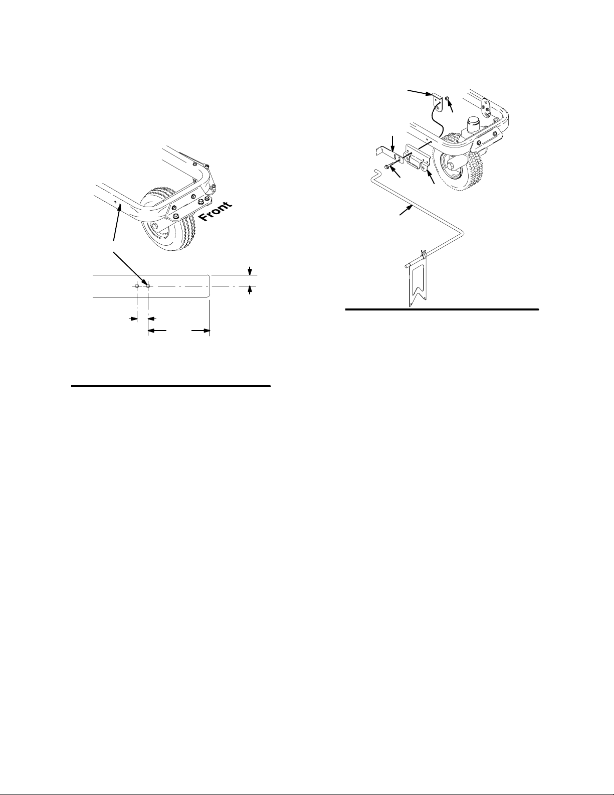
1. Drill two holes in side of frame to which pointer will
be attached, as shown in Fig. 1.
Fig. 1
1.0 in.
1.0 in.
A = 5.55 in. — LineLazer 3900, 5900, 200HS (already drilled)
Front
4X Ĭ.330
through both walls
A = 6.55 in. — LineLazer 3500 & 5000 (must be drilled)
A
ti6539a
2. Fig. 2. Slide outside bracket (9) onto rod (1). Slide
inside bracket (6) onto rod.
Fig. 2
ti6540b
7
8
6
1
9
11
NOTE: Steps 3 and 4 apply to all LineLazers.
3. Locate brackets on frame so bracket holes align
with frame holes and bracket flanges rest on top of
frame and rod sits below.
4. Fasten brackets with two flange screws (7) and two
lock nuts (8).
Operation
For new stripes:
The dual-point guide allows for line placement on the same side of the layout string or chalk, traveling in either
direction. Center the pointer on the center of the paint guns when painting. Alternate between points for each
direction you travel.
DPut the line guide in the down position for painting, as shown below.
DWhen not painting, swing the line guide up to the storage position.
DAttach tie straps through small holes of indicator (2) for a drag-type indicator.


