Columbus Instruments Exer 3/6 User manual

Treadmill Hardware Manual
June 8, 2022
1011-0002 v1.02
950 North Hague Avenue
Columbus, Ohio 43204-2121 USA
Sales: sales@colinst.com
Service: servi[email protected]om
Phone: (614) 276-0861
Fax: (614) 276-0529
Toll Free: 1-800-669-5011
http://www.colinst.com


Treadmill Hardware Manual 1011-0002 v1.02
3
Table of Contents
Treadmill Types ....................................................................................................................................................... 5
Exer 3/6 Treadmill................................................................................................................................................... 6
1 –System Overview........................................................................................................................................... 6
1.1 System Specifications.......................................................................................................................... 6
1.2 Treadmill Stimulus Detection Overview.................................................................................................... 8
2 –Hardware Setup............................................................................................................................................. 8
2.1 Item Inventory........................................................................................................................................... 8
2.2 Assembly ................................................................................................................................................... 9
2.3 Connecting Components......................................................................................................................... 16
3 –Treadmill Controller User Menu ................................................................................................................. 19
3.1 Restore Defaults...................................................................................................................................... 20
3.2 Serial Number.......................................................................................................................................... 20
3.3 Run-Time Meter...................................................................................................................................... 21
3.4 Run-Time Odometer................................................................................................................................ 21
3.5 Fan Voltage.............................................................................................................................................. 21
3.6 Unit ID ..................................................................................................................................................... 21
3.7 Baud Rate ................................................................................................................................................ 21
3.8 AutoCal Speed......................................................................................................................................... 22
3.9 Acceleration Settings............................................................................................................................... 22
3.10 Operating Mode.................................................................................................................................... 23
3.11 Calibrate Shock...................................................................................................................................... 24
3.12 Exit......................................................................................................................................................... 25
3.13 Treadmill Stimulus Detection User Menu............................................................................................. 25
4 –Stand Alone General Exercising without the PC.......................................................................................... 26
4.1 Stand Alone Initialization ........................................................................................................................ 26
4.2 User Menu Settings................................................................................................................................. 26
4.3 Loading Subjects...................................................................................................................................... 26
4.4 Controls................................................................................................................................................... 27
4.5 Treadmill Stimulus Detection.................................................................................................................. 28
5 –Maintenance ............................................................................................................................................... 31

4
Treadmill Hardware Manual 1011-0002 v1.02
5.1 Treadmill Belt Tracking............................................................................................................................ 31
5.2 Treadmill Belt Tension............................................................................................................................. 32
5.3 Cleaning................................................................................................................................................... 32
Modular Treadmill................................................................................................................................................. 32
6 –System Overview......................................................................................................................................... 32
6.1 System Specifications.............................................................................................................................. 32
6.2 Treadmill Stimulus Detection Overview.................................................................................................. 34
7–Hardware Setup ........................................................................................................................................... 34
7.1 Item Inventory......................................................................................................................................... 34
7.2 Assembly ................................................................................................................................................. 35
7.3 Connecting Components......................................................................................................................... 43
8 –Treadmill Controller User Menu ................................................................................................................. 47
8.1 Restore Defaults...................................................................................................................................... 48
8.2 Serial Number.......................................................................................................................................... 48
8.3 Run-Time Meter...................................................................................................................................... 48
8.4 Run-Time Odometer................................................................................................................................ 48
8.5 Fan Voltage.............................................................................................................................................. 49
8.6 Unit ID ..................................................................................................................................................... 49
8.7 Baud Rate ................................................................................................................................................ 49
8.8 AutoCal Speed......................................................................................................................................... 49
8.9 Acceleration Settings............................................................................................................................... 50
8.10 Operating Mode.................................................................................................................................... 50
8.11 Calibrate Electric Stimulus..................................................................................................................... 51
8.12 Exit......................................................................................................................................................... 52
8.13 Treadmill Stimulus Detection User Menu............................................................................................. 52
9 –Stand Alone General Exercising without the PC.......................................................................................... 53
9.1 Stand Alone Initialization ........................................................................................................................ 53
9.2 User Menu Settings................................................................................................................................. 53
9.3 Loading Subjects...................................................................................................................................... 54
9.4 Controls................................................................................................................................................... 54
9.5 Treadmill Stimulus Detection.................................................................................................................. 56
10 –Maintenance ............................................................................................................................................. 59

5
Treadmill Hardware Manual 1011-0002 v1.02
10.1 Treadmill Belt Tracking.......................................................................................................................... 59
10.2 Treadmill Belt Tension........................................................................................................................... 59
10.3 Removal of Shocker Assembly .............................................................................................................. 59
10.4 Cleaning................................................................................................................................................. 59
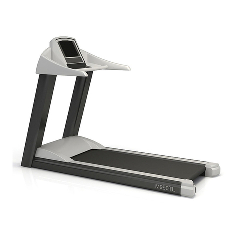
Treadmill Types
Exer 3/6 Treadmill: Modular Treadmill:

6
Treadmill Hardware Manual 1011-0002 v1.02
Exer 3/6 Treadmill
1 –System Overview
The Columbus Instruments Exer 3/6 Treadmill is an economical treadmill designed for general purpose animal
exercising. The basic system consists of two separate units: the Treadmill Controller, and the Treadmill. The
Treadmill can have up to 6 lanes.
Summary of the features:
•Can exercise 1-3 rats or 1-6 mice simultaneously
•Any combination of clear or opaque lane dividers can be used
•25°of inclination in 5°steps, with optional 15°declination in 5°steps
•Brushless motor ensures long life with no maintenance
•Treadmill belt speed adjustable from 1.5 to 102.3 meters/minute
•Acceleration is adjustable from 0.0 to 25.5 meters/minute/second
•Automatically timed exercise sessions up to 4:15:59s in 1s steps
•Automatic distance limited exercise sessions up to 9,999.0 meters in 1.0-meter steps.
•Optional automatic treadmill belt speed and odometer distance calibration using the speed sensor
•Optional Electrical Stimulus, up to 2.34 mA, 200ms pulse, 1, 2, or 3 times per second
•Optional Air-Puff Stimulus, up to 40PSI, 200ms pulse, 1, 2, or 3 times per second
1.1 System Specifications
Physical Dimensions: 83.8 x 50.8 x 50.8cm (33.0” x 20.0” x 20.0”)
Physical Weight: 25kg (55lbs)
Mouse Lane Dimensions: 5.7 x 41.3cm (2.3” x 16.3”)
Mouse Platform: 5.7 x 10.7cm with 0.1cm brush (2.3” x 4.2” with 0.4” brush)
Rat Lane Dimensions: 11.8 x 41.3cm (4.6” x 16.3”)
Rat Platform: 11.8 x 10.7cm with 0.1cm brush (4.6” x 4.2” with 0.4” brush)
Angle of Inclination: 0°-25°above the horizontal in 5°steps.
1.1.1 Optional Electric Stimulus
Mouse Grid Dimensions: 0.3 x 11.4cm rods, 1.0cm apart, 5 - 6 rods typical
(0.1” x 4.5” rods, 0.4” apart, 5 - 6 rods typical)
Rat Grid Dimensions: 0.3 x 11.4cm rods, 1.0cm apart, 11 rods typical
(0.1” x 4.5” rods, 0.4” apart, 11 rods typical)
Stimulus Voltage: 117VAC 50/60Hz
Stimulus Current: up to 2.34mA
Stimulus Durations: 200mS
Stimulus Repetition Rate: 1, 2, or 3Hz
Stimulus Control: 2-position toggle switch (on/off) for each lane
The INTENSITY adjusts the maximum current for each lane

7
Treadmill Hardware Manual 1011-0002 v1.02
1.1.2 Optional Air-Puff Stimulus
Stimulus Pressure: 0-2069mmHg (0-40PSI), 19-liter (5-gallon) reservoir typical
Stimulus Nozzles: Six per Mouse Lane, Ø 1.4mm x 13.9mm (Ø 0.055in x 0.545in)
Stimulus Duration: 200mS
Stimulus Repetition Rate: 1, 2, or 3Hz
Stimulus Control: 2-position toggle switch (on/off) for each lane
The INTENSITY adjusts the relative sensitivity of the capacitive touch
sensors
1.1.3 Optional Downhill Running Adapter
Adapter Dimensions: 25.4 x 49.5 x 27.7cm (10.0 x 19.5 x 10.9in)
Adapter Weight: 1.0kg (2.3lbs)
Adapter Effect: adds +30cm (+11.8in) to the overall height
Angle of Declination: 0°–15°below the horizontal in 5°steps
1.1.4 Treadmill Controller
Power Requirements: 200 watts, 100, 115, or 230VAC, 50/60Hz (factory selected)
Physical Dimensions: 36.8 x 30.5 x 10.9cm (14.5 x 12.0 x 4.3in)
Physical Weight: 4.8kg (10.6lb)
User Controls: 3 x Push-Button Rotary Encoders
Speed Sensor Connection: 6.35mm (1/4in) Female Stereo Phone Jack
Fan Connections: 3.50mm (1/8in) Female Mono Phone Jack (x4)
CI-Bus Connections: 8p8c (RJ45 Ethernet) Modular Jack (x2)
Shocker Connection: 15-pin Female D-SUB
Motor Connection: 6-position Molex 5566 Mini-Fit Jr Male Header
Belt Speed Range: 0.0 –102.3 meters/minute
Acceleration Range: 0.0 –25.5 meters/minute/second
Time Limited Range: 0:00:01s to 4:15:59s
Distance Limited Range: 1.0 to 9,999.0 meters
1.1.5 Optional Calibration Wand
Power Requirements: 5VDC @ 100mA
Physical Dimensions: 20.3 x 4.6 x 4.3cm (8.0 x 1.8 x 1.7in)
Physical Weight: 0.2kg (0.5lb)
Connector: 6.35mm (1/4in) Stereo Phone Plug
Wheel Diameter: 4.128cm (1.625in)
Output: 100 pulses per revolution (771 pulses/meter)
1.1.6 CI-Bus Switch Mini
Power Requirements: 5VDC @ 500mA
Physical Dimensions: 6.63 x 6.6 x 2.7cm (2.6 x 2.3 x 1.1in)
Physical Weight: 0.06kg (0.137lb)
Computer Connection: USB 2.0 Type “B” Jack

8
Treadmill Hardware Manual 1011-0002 v1.02
1.2 Treadmill Stimulus Detection Overview
The Columbus Instruments Treadmill Stimulus Detection is designed to work with the electrical or air-puff
stimulus. The Treadmill Stimulus Detection will monitor the stimuli presented to each channel (lane) and the
calculate various data outputs from them.
Yoked Stimulus allows the stimuli delivered to an odd-numbered channel to be reproduced on the next even-
numbered channel. This ensures that quarantined control subjects receive the same stimuli as the test subjects
within an experiment session. The Exer 3/6 in “Rat” mode can support only two channels yoked: 1 & 2. The
“Mouse” mode can support all six channels: 1 & 2, 3 & 4, 5 & 6.
1.2.1 System Specifications
Power Requirement: 6 watts, 115 or 230VAC, 50/60Hz (factory selected).
Power Fuses: 2A Slow-Blow.
Physical Dimensions: 36.8 x 30.5 x 10.9cm (14.5 x 12.0 x 4.3in).
Physical Weight: 2.8kg (6.1lb)
User Controls: 3 x Push-Button Rotary Encoders
CI-Bus Connections: 8p8c (RJ45 Ethernet) Modular Jack (x2)
Source Stimulus: 15-pin Female D-SUB “From Controller” port.
Output Stimulus: 25-pin Female D-SUB “To Treadmill” port.
2 –Hardware Setup
2.1 Item Inventory
A typical Treadmill system contains the following items:

9
Treadmill Hardware Manual 1011-0002 v1.02
1 x CI-Bus Hub or CI-Bus Switch Mini
1 x USB cable, 2m (6ft), A-B
1 x CI-Bus communication cable, 2m (6ft) (CAT5 network cable, 8p8c (RJ45), ethernet)
Treadmill Controller with AC power cord
1 x Motor Cable, 2m (6ft), 6-circuit, plug-plug
1 x Shocker Cable, 1.8m (6ft), 15-pin
1 x Calibration Wand
1 x Instruction Manual
1 x Treadmill Software Flash Drive (if using with Oxymax)
1 x Exer 3/6 Treadmill (shown with optional shock grid)
1 x Treadmill Lid
1 x Feces Tray
1 x Package of lane dividers: 5 opaque and 2 clear dividers
1 x Inclination Rod, 51cm (20in) with spring pin
2 x Thumbnuts for securing the treadmill lid
1 x 7/16in open-end wrench for adjusting the tension of the treadmill belt
2.2 Assembly
You may need the following tools for assembling the system:

10
Treadmill Hardware Manual 1011-0002 v1.02
Philips screwdriver, medium tip
Flathead screwdriver, small tip
7.5mm (5/16in) wrench or adjustable crescent wrench
It is recommended to use an AC power strip to provide a common access to AC power for all components of
the Treadmill system and host computer.
2.2.1 Treadmill Assembly
The Exer 3/6 Treadmill is about 90% assembled.
•Remove any protective plastic film that may cover pieces of the treadmill.
•Insert spring pin into the Inclination Rod in the hole that is most near the end. This end of the
Inclination Rod is the bottom.
•Roll the Exer 3/6 on its side.
•Insert the top of the Inclination Rod through the hole in the front of the treadmill.
•Roll the Exer 3/6 onto its feet.
•Remove any protective plastic film that may cover the lane dividers.
•Insert one of the clear lane dividers into the set of slots on the far side of the treadmill.
•Insert all the opaque dividers into the slots in the middle of the treadmill. Leave one set of slots vacant
between the 2 dividers for rats or populate all 5 slots for mice.
•Remove all protective plastic film that may cover the treadmill cover and lid.

11
Treadmill Hardware Manual 1011-0002 v1.02
•Fold the lid onto the cover.
•Place the holes of the cover over the posts in the front of the treadmill and secure with the two
thumbnuts.
•Unfold the lid onto the treadmill and secure with the 2 clips.
•Place the feces tray underneath the treadmill below the platform and treadmill belt.
This completes the assembly of the Exer 3/6 Treadmill.
2.2.2 Downhill Running Adapter
If the Exer 3/6 Treadmill came with the Downhill Running Adapter, then the system will contain the following:
1 x Right leg with rubber foot.
1 x Left leg with rubber foot.
2 x Braces for the legs.
9 x #6-32 x 3/8-in screws.
9 x #6-32 hex nuts with nylon locking inserts.
To setup the Downhill Running Adapter, do the following:
•Remove any protective plastic film that may cover the pieces of the Downhill Running Adapter.
•Raise the front of the treadmill so the treadmill will reset entirely on the rear panel. Remove the
Inclination Rod with spring pin and set aside.
•Using the Philips screwdriver and 5/16in wrench, remove both feet from the bottom of the treadmill.

12
Treadmill Hardware Manual 1011-0002 v1.02
•Using one screw and nut, connect the two braces together in the middle. Do not tighten. The screw
and nut should hold the braces closely together but allow them to move.
•Using four screws with nuts, connect the legs and the braces together in the orientation as shown.
Again, do not tighten. The screws and nuts should hold the pieces closely together but allow them to
move.
•Now, apply pressure to force the rubber feet of the legs apart and tighten the two screws and nuts
near the feet. This will hold the feet farthest apart for better stability.
•Position the assembled Downhill Adapter with the braces on the bottom next to the bottom of the
treadmill as shown and secure with the remaining 4 screws and nuts. Tighten completely.
•Reposition the spring pin from the hole at the bottom to the hole in the middle of the Inclination Rod.

13
Treadmill Hardware Manual 1011-0002 v1.02
•Insert the inclination Rod through the hole in the front of the treadmill. Then lower the front so the
treadmill rests on the Downhill Adapter feet and the Inclination Rod
•Tighten all remaining screws and nuts of the legs and braces.
This completes the assembly of the Downhill Adapter.
2.2.3 Air-Puff Stimulus
The Air-Puff Stimulus includes the following:
1 x ¼in diameter air supply line with quick-connect fittings, 6m (20ft)
1 x Air Reservoir 19 liter (5 gallon)
1 x ½” diameter air supply line. 2.4m (8ft)
1 x Molex Mini-Fit Jr valve power cable, 2m (6ft), 2-circuit, plug-plug
You may also need the following tools/supplies:

14
Treadmill Hardware Manual 1011-0002 v1.02
Teflon tape or Teflon pipe sealant
15mm (9/16in) Open-End Wrench or Adjustable Crescent Wrench
WARNING!!! Place the protective caps over the open ports of air-fittings when not in use.
To setup the Air-Puff Stimulus, do the following:
•Place the Air Reservoir near the treadmill, but out of the way
•Remove and save the protective caps from the air fittings on the rear of the treadmill and the Air
Reservoir.
•Place a mark 2.54cm (1in) from the end of the 2.4m (8ft) air-supply line. Then fully insert the 2.4m (8ft)
tube into the air fitting on the rear of the treadmill. The mark should be flush with the end of the
fitting.
•Place a mark 2.54cm (1in) from the free end of the 2.4m (8ft) air-supply line. Then fully insert the 2.4m
(8ft) tube into the air fitting on the air reservoir. The mark should be flush with the end of the fitting.
•Place a mark on the free end of the 6m (20ft) air-supply line 19mm (¾in) from the end. Then, fully
insert the 6m (20ft) tube into the fitting on the reservoir brass tee. The mark should be flush with the
end of the fitting.

15
Treadmill Hardware Manual 1011-0002 v1.02
•Using Teflon tape or pipe sealant, attach the female quick-connect fitting to the pressure-regulated
source of air (compressed air bottle shown). Use a 9/16in open-end crescent wrench to fully tighten.
•Join the other end of the 6m (20ft) air-supply line to the quick-connect fitting.
•Connect the 2-circuit valve power cable between the “Valve Power” port of the Treadmill Controller
and the 2-position Molex Mini-Fit Jr jack on the Exer 3/6 Treadmill. Be sure the locking lever snaps
down to secure the cable to the ports.
This completes the assembly of the Air-Puff Stimulus.
WARNING!!! Do not pressurize the air puff system beyond 2069mmHg
possible damage may result to connector fittings and equipment.

16
Treadmill Hardware Manual 1011-0002 v1.02
2.2.4 Electric Stimulus
The stimulus grid comes pre-attached to the treadmill. To connect the stimulus grid, go to SECTION 2.3.
2.2.5 Setting Angle of Inclination or Declination
The angle of inclination is set by the location of the spring pin in holes of the Inclination Rod. The holes range
from 0°to 25°in 5°steps. With the Downhill Running Adapter, the holes range from 10°to -15°in 5°steps.
•Lift the front of the treadmill to release the pressure on the spring pin and remove it from the
Inclination Rod.
•Now position the treadmill slightly above the new height of the inclination and replace the spring pin
into the corresponding hole in the Inclination Rod.
•Slowly lower the treadmill onto the spring pin.
2.3 Connecting Components
•Place the CI-Bus Hub interface near the host computer. Remove the orange terminator if installed.
Using the USB cable, connect the interface to the host computer. The power indicator should be lit
continuously.
•Connect one end of the CI-Bus communication cable to any of the ports. DO NOT LOSE THE
TERMINATOR.
•Connect the other end of the CI-Bus communication cable to one of the CI-Bus ports of the treadmill
controller.
•Install the orange terminator into the other CI-Bus port.

17
Treadmill Hardware Manual 1011-0002 v1.02
•Connect the shocker cable between the “Shocker” port of the Treadmill Controller and the 15-pin D-
SUB jack on the Exer 3/6 Treadmill.
•Use the fasteners built into the cable ends to secure the cable to the ports.
•Connect the motor cable between the “Motor” port of the Treadmill Controller and the 6-position
motor cable jack on the Exer 3/6 Treadmill. Be sure the locking lever snaps down to secure the cable to
the ports.
•Connect the AC power cord to the rear panel AC power receptacle of the Treadmill Controller and
insert the other end into an appropriate AC outlet.
DO NOT switch on the Treadmill Controller at this time! Refer to SECTION 4 for further instructions.
2.3.1 Connecting Treadmill Stimulus Detection
A typical Treadmill Stimulus Detection system may contain the following items:

18
Treadmill Hardware Manual 1011-0002 v1.02
Treadmill Stimulus Detection with AC power cord
1 x CAT5 network cable, 0.3m (1ft), 25-pin
1 or more detection cables, 1.8m (6ft), 25-pin
1 x Instruction Manual
To connect the Treadmill Stimulus Detection to the Treadmill Controller:
•Switch OFF the Treadmill Controller and remove all the shocker cables from the treadmill system.
•Place the Treadmill Stimulus Detection on top of the Treadmill Controller. Be sure to center the
cabinets feet over the top of the locating pins.
•Using one of the shocker cables, connect the “Shocker” port of the Treadmill Controller to the “From
Controller” port of the Treadmill Stimulus Detection.
(other cables removed for clarity)
•Remove the CI-Bus terminator from the Treadmill Controller.
•Use the short 0.3m (1ft) CAT-5 network cable and connect the adjacent “CI-Bus” ports of the Treadmill
Stimulus Detection and Treadmill Controller together.
•Plug the CI-Bus terminator into the top port of the Treadmill Stimulus Detection.

19
Treadmill Hardware Manual 1011-0002 v1.02
(other cables removed for clarity)
•Connect the Treadmill Stimulus Detection to the same source of AC power as the Treadmill Controller.
To Connect the Treadmill Stimulus Detection to the Exer 3/6 Treadmill:
•Using a detection cable, connect the “To Treadmill” port of the Treadmill Stimulus Detection to the 25-
pin male D-SUB port on the back side of the treadmill.
(other cables removed for clarity)
3 –Treadmill Controller User Menu
The User Menu is used to set and view various parameters which are saved within the Treadmill Controller.
Access to the menu is provided by unique button presses when the treadmill belt mode is set to STOP and not
under computer control.
If under computer control (indicated by the speed setting displayed with “C” instead of “S”), press the MODE
button to set the treadmill belt to STOP. Then press the ODOMETER RESET button to restore control back to
the user.

20
Treadmill Hardware Manual 1011-0002 v1.02
To access the User Menu:
Press and hold the RATE button.
Press and hold the MODE button.
Then press and release the ODOMETER RESET button.
Release the RATE and MODE buttons.
The screen will display: USER MENU, and then will position you in the menu at the option for automatic speed
and distance odometer calibration: AutoCal Speed.
The menu options are as follows:
•Restore Defaults
•Serial Number
•Run-Time Meter
•Odometer
•Fan Voltage
•Unit ID
•Baud Rate
➢AutoCal Speed
•Accel
•Mode
•Calibrate Shock
•Exit
The INTENSITY knob is used to navigate the options on the User Menu. Clockwise rotations will move the
selection arrow up, and counterclockwise rotations will move the arrow down.
Press the ODOMETER RESET button to select an option to edit and save any changes.
Use the SPEED knob to adjust the settings and values while editing.
3.1 Restore Defaults
The top option on the menu list. This is used to restore all the factory settings saved during the treadmill’s
factory calibration. This may be necessary during service to restore a known configuration should for any
reason the current settings be unknown or have become corrupt and the treadmill system is non-responsive.
Press the ODOMETER RESET button to select this option. The screen will display: Restore Defaults Are
You Sure?
Press and hold the ODOMETER RESET button to restore the factory settings, press and release to cancel.
3.2 Serial Number
This option is used to see the electronic serial number which should match the Columbus Instruments serial
tag on the outside of the cabinet. For service, this number may be referenced to lookup any specific details or
notes about your specific Treadmill and Controller. This option is non-editable.
Other manuals for Exer 3/6
2
Table of contents
Other Columbus Instruments Treadmill manuals
Popular Treadmill manuals by other brands

Sunny Health & Fitness
Sunny Health & Fitness SF-T7942 user manual

Omega Speaker Systems
Omega Speaker Systems Advance 300 Calibration instructions

BH FITNESS
BH FITNESS Columbia Instructions for assembly and use

Weslo
Weslo Cadence 3280 manual

LIFESTYLER
LIFESTYLER 831.297242 owner's manual

Precor
Precor ENERGY SERIES Service manual