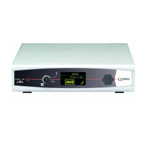
Comeg SOPRO 218 User manual

INTUITIVE
CONNECTION
User manual
Manuel d’utilisation
Manual de usuario
Betriebsanleitung
Manuale per utilizzatore
1

32

3
User manual ____________________________________________5
Manuel d’utilisation _____________________________________25
Manual de usuario ______________________________________45
Betriebsanleitung
______________________________________65
Manuale per utilizzatore _________________________________85

4
INTUITIVE
CONNECTION
5

INTUITIVE
CONNECTION
English
5
ENGLISH

6
ENGLISH
7

6
ENGLISH
7
Contents
1 Introduction _____________________________________ 8
2 Presentation of the Xenon light source _______________ 9
3 Precautions for use ______________________________ 10
4 Regulatory recommendations _____________________ 11
5 Installation _____________________________________ 12
6 Description of the front panel ______________________ 13
7 Description of the rear panel ______________________ 14
8 Lamp change ___________________________________ 15
9 Aer sales service _______________________________ 17
10 Specifications ___________________________________ 18
11 Electromagnetic compatibility _____________________ 19
12 Symbols ________________________________________ 22

8 9
ENGLISH
Thank you for your confidence by purchasing this device.
To take full advantage and comply with all necessary precautions, you should carefully read this
manual and be well acquainted with its contents.
Sentences containing the symbol are points requiring special attention.
Sentences containing the symbol are for information.
1 Introduction

8 9
ENGLISH
2 Presentation of the
Xenon light source
This Xenon light source is especially designed for endoscopic applications.
Its colour temperature is very close to day light, its high intensity light and its servo-shutter
make of it the ideal pluridisciplinary medical tool.
The package includes:
• The light source with a light cable adapter
• A power cable
• A user manual.
This equipment is delivered in a pasteboard cardboard box. You must keep this element for
further transport.

10 11
ENGLISH
3 Precaution for use
• Only qualified personnel are allowed to use this kind of equipment, after being trained.
• Please read this instruction manual carefully before installing and operating the light
source.
• Before connecting the light source to the mains, check and ensure that the electrical
parameters at your facilities are completely identical with the data specified on the
equipment. The identification refill mentioning the service tension, the electrical
consumption, etc. is located on the rear panel of the device.
CAUTION: HIGH VOLTAGE inside the equipment!
Do not open the rear panel of the unit! Service only by authorised personnel!
Never place your eyes in the axis of the light output, neither at the tip of the light cable.
• In order to avoid any risk of burning or electrocution, do not expose this device to rain or
excessive humidity.
• In case any fluid getting into the devices, turn the unit immediately off and remove the plug
from the mains.
• Never leave the power cable fall and never place heavy objects on it. If the power cable is
damaged, immediately disconnect the light source from the mains. Never have it working
with a damaged cable!
• To remove the power cable, handle it by the tip not to damage it. Never draw on the cable
itself.
• The mains plug must be close to the light source and easy to reach.
• Check the ventilation to avoid any overheating of the device: ensure that the minimum
space is 15cm on left, right, and rear side of the unit.
WARNING: NEVER operate the equipment near any inflammable gases.
NEVER place the device close to a heat source or to places exposed to vibrations or
shocks.
• Do not use abrasive / corrosive products to wipe the surface of the light source: only use
cleansers and disinfecting liquids classically used in hospitals. Clean the light source in
accordance with your hospital’s standard cleansing procedures.
• This light source and its accessories do not require any specific treatment at the end of
their life.
WARNING! DO NOT PLACE THE DISTAL END OF THE LIGHT GUIDE DIRECTLY ON THE
PATIENT AND/OR ON ANY OTHER FLAMMABLE MATERIALS.
It is advisable to have a second light source available in the operating room to use if an
absence or degradation of performance is observed.
WARNING : Use of accessories, transducers, and cables other than those specified
or supplied by the manufacturer of this device may cause an increase in electromagnetic
emissions or a decrease in the immunity of this device and may cause improper operation.
WARNING : Do not use RF Portable Communication Devices (including peripherals such
as antenna cables and external antennas) closer than 30 cm (12 inches) to any part of the
[APPLIANCE or SYSTEM], including cables specified by the manufacturer. Otherwise, the
performance of these devices may be impaired.

10 11
ENGLISH
4 Regulatory
4.1 Conformity
This device has been designed and manufactured by a company with a certified quality
system.
It complies with the requirements of the European Directive 93/42/CEE related to medical
devices.
As a result, it complies in particular with the ad hoc electric safety (IEC) and Electromagnetic
Compatibility (EMC) standards.
4.2 Electromagnetic interference & electrostatic discharges
Although this product complies with the EMC standards, it is possible under very special
circumstances that it may disturb other devices or even be disturbed in turn by other devices
or by an unfavourable EM environment.
To prevent such situations, it is recommended :
• To take care of the quality of the electric network (and particularly the grounding system
of all the devices and carriages) ;
• To keep the device away from Electromagnetic sources (e.g., compressor, motor, transformer,
HF generator, etc.).
This device can be disturbed by a strong electrostatic discharge.
In such a case, turn off and then turn on the device and follow again the start instructions.
If the phenomenon repeats, the grounding connections and system should be checked.
4.3 Materio vigilance
Like for any medical system, this device is subject to the provisions pertaining to materio
vigilance; any serious dysfunction must therefore be promptly notified to the competent
authorities and the manufacturer with the greatest possible precision.
4.4 End of life
This appliance is marked according to the European Directive 2002/96/EEC on Waste
Electrical and Electronic Equipment (WEEE).
By ensuring this product is disposed of correctly, you will help prevent potential negative
consequences for environment and human health, which could otherwise be caused by
inappropriate waste handling of this product.
The symbol on the product, or on the documents accompanying the product, indicates
that this appliance may not be treated as household waste. Instead it shall be handed over to
the applicable collection point for recycling of electrical and electronic equipment.
Disposal must be carried out in accordance with local environmental regulations for waste
disposal.
For more detailed information about treatment, recovery and recycling of this product, please
contact your local city office your household waste disposal service or the dealer to whom
you purchased the product from.

12 13
ENGLISH
5 Installation
Take care that the location of the light source is well-ventilated (minimum 15cm space on
left, right, and rear side of the light source).
5.1. Connection of the front panel
• This light source is equipped as standard with a Storz light cable adapter
1
.
• Insert your light cable in the “light guide” hole C1 until a «click» is heard.
• Connect your endoscope to the other tip of the light cable.
5.2. Connection of the back panel
• Connect the power cable to the mains plug of the light source C2 .
• Connect this power cable to the mains.
• If needed, connect a grounding cable to the ground contact identified with a green and
yellow washer and the following sign:
For the USA and Canada, you must use the “hospital grade” cable supplied and connect it
to a “hospital grade” mains outlet.
1. Other adapters available on request.

12 13
ENGLISH
6 Description
of the front panel
6.1. Power switching
The light source is equipped with:
-A MAIN switch, located on the back panel C2 .
-A STAND-BY, on the left side of the front panel S1 .
Turn the MAIN switch on: the LED alongside Lof the STAND-BY blinks.
Press the STAND-BY S1 button to power the bulb: the LED lights continuously.
6.2. Anti blinding feature
When starting operating the light source, you are in stand-by position with 10% light intensity.
You are also obtaining this low position when removing the light cable.
Whenever the user wishes to, he can immediately reduce the brightness to 10% by pressing S2 .
6.3 LCD display
D
The LCD displays shows the light intensity (from 0 to 10) and the lamp life. It also shows if the
light source is in Stand By position.
NOTE : After changing the bulb, do not forget to reset the hour meter (see §8.2).
6.4 Temporisation
A 60 seconds lap time is required when turning off the device before turning it on again.
Meanwhile the LED is blinking rapidly. This procedure allows the lamp to cool down.
6.5. Brightness adjustment
The light source is equipped with a mechanical iris to adjust the quantity of light delivered.
This iris is composed of a metal disk that more or less comes to stop the flow of the lamp,
which is powered at constant tension. This system, contrarily to electrical diaphragms
modulating the tension applied to the lamp, allows keeping a constant colour temperature
whatever the requested level of light is.
To modify the light intensity of the light source, press the right button S4 to increase the level
of light and the left button S3 to decrease the light (minimum and maximum positions light
the corresponding button).

14 15
ENGLISH
7.1. Mains plug
The light source is powered via its mains plug, which must be linked to the mains accordingly
to the specifications listed on the rear panel.
This plug includes a fuses trap. The 2 fuses are of T 4 A. The T of “T 4 A” means “temporised”.
During a fuses change, it is imperative to disconnect the light source from the mains and
to use the same type of fuses. UL/CSA only.
7.2. Identification and symbols on the back panel
The indications and symbols mentioned on the back panel allow identifying the light source in
conformity with the International standards IEC 60601-1 and comply with the requirements of
the 93/42/EEC European standard.
7 Description
of the rear panel

14 15
ENGLISH
8 Lamp change
Replacement of a lamp must only be done by qualified personnel and in accordance
with required safety requirements.
The high power and currents produced by the power supply involves an accurate knowledge of the
product.
Send back your light source to your supplier who will take the opportunity to check if everything is ok.
DANGER: before any handling, let the lamp cool down!
When replacing lamp, always wear protection glasses and use protection gloves to protect hands
and eyes.
Once lamp is removed, place the defective bulb into its original package box; never leave lamp
lying around. Please return defective bulb in original packaging to supplier for disposal.
Do not bend or press the lamp or any parts of it. Do not include any force on the lamp or its parts.
Only use genuine bulbs, identical to the one delivered in the brand new light source.
8.1. Lamp change procedure (see next page)
• Switch off the device and disconnect it from mains supply.
• Place the device on a safe flat base.
1. Unscrew the 4 screws to remove the left side cover, in order to reach the lamp.
2. Unplug the white plug by pressing it on its left and right sides then pulling it out.
3. Unscrew the device that is holding the bulb in place.
4. Remove lamp from its holder, by pulling it out (towards backside direction).
DO NOT LEAVE FINGERPRINTS ON THE BULB, HOLD IT WITH GLOVES
• Insert new lamp and reassemble by considering procedure in the reverse order.
• Make sure the bulb is well positioned: the finger on the metal plate fits in a hole on the
perimeter of the bulb.
Make sure that at least one spare lamp is available in stock.
8.2. Hour meter reset
In order to reset the counter to zero after each change of lamp:
-The source must be on standby: the led Lflashing.
-You then need to press the brightness key S4 and the Standby key S2 at the same time
and hold for at least 2s.
The hour meter goes back to zero.
REMARK: The typical lifetime of the bulb is of 500 hours. This is an average value at 30 min. ON
and 15 min. OFF. Shorter use can reduce the lifetime significantly.

16 17
ENGLISH
8 Lamp change
Correspondence
1
3
5
2
4
6

16 17
ENGLISH
9 Aer-sales service
No special maintenance is necessary on the light source.
You just have to care about light intensity and to change the lamp if necessary.
Nevertheless you may face a minor incident during its use.
The causes and effects of incidents to which you could easily remedy are described below.
For all other cases, please contact our Maintenance Service.
9.1. No LED of the front panel lights when you switch the
light source on
• Check if the mains plug on the rear panel of the light source is well connected to the mains.
• Check the good state of the fuses (use only fuse specified on the rear face: T 4A).
9.2. The on/off LED lights but there is not enough light
• Press on the right button to check if the iris is not completely closed.
• Change your lamp.
• Check the quality of your light cable and optics.
9.3. The images are too bright
• Check if the iris is not completely open.
9.4. There is no more light but the fan is still ventilating and
the led of the 2 buttons for brightness are flashing
The light source is equipped with a safety device that stops the bulb power supply if the
temperature inside the light source is too high. Once cooled off, the light source can be
operated again.
• Check that there is enough space around the light source to ensure a correct cooling (15cm on
each side).
• Check that nothing is obstructing the ventilation on the back panel.
If the problem remains and if you are led to send us back the light source, be careful to do it in its
original wrapping. Likewise, you must send us the whole system (even the light cable you use).
Please, join an explanatory note to the expedition bill, relative to the default you noticed.
At the reception of your equipment, you will have to check its state and, if necessary, to enter a
reservation on the delivery bill. You will then have 48 hours to confirm them by recommended
letter addressed to the carrier. Beyond this delay, the carrier may deny these reservations. In
the case the equipment shipped by us suffered damages during the travel, the amount of the
repairing will be charged either to the carrier if the reservation were entered in the delays, or to
the consignee in the contrary.
Think to check rapidly the good functioning of the equipment that has just travelled.
All repairs on the light source being performed by us, no technical data will be provided.
Do not use abrasive products to wipe the surface of the light source, use a smooth cloth.

18 19
ENGLISH
10 Specifications
• Lamp lifetime: 500 hours (Average value at: 30 min. ON and 15 min. OFF)
• Mechanical iris.
• Light intensity adjustment, thanks to touch buttons
• Light intensity and lamp age displayed on the screen
• Stand-by button closing the iris to 10% of light intensity
• Electrical requirements: 100 -230 V ~ / 50 - 60 Hz
• Dimensions: D: 300mm; W: 311mm; H: 125 mm
• Weight: 5 kg.
• 2 Fuses T 4A. (UL/CSA only)
• Temperature range - in function: +10°C to +40°C
• Maximum relative air humidity - in function: 85 %
• Asmospheric pressure: 800hPa to 1060hPa
• Temperature range - in storage: -20°C to +45°C
• Maximum relative air humidity - in storage: 85 %
• Continuous service.
• Not protected against waterfalls (IPX0).
• Not adapted to a use close to a mixture of inflammable anaesthetic with air, oxygen or nitrous
oxide.
Conform to the European directive 93/42/CEE.
100 Watts Xenon light source
• Nominal operating power: 100 Watts
• Colour temperature: 5800°K
• Power consumption: 240VA
180 Watts Xenon light source
• Nominal operating power: 180 Watts
• Colour temperature: 5800°K
• Power consumption: 450VA
300 Watts Xenon light source
• Nominal operating power: 300 Watts
• Colour temperature: 6200°K
• Power consumption: 485VA

18 19
ENGLISH
11 Electro-magnetic
compatibility
Guide and declaration by manufacturer – electromagnetic emissions
The reference system, «Xenon light source» is designed to be used within the electromagnetic
environment specified below. The user should ensure that it is indeed used within this environment
WARNING: Avoid using this device next to other devices or stacked with them; this could cause
a malfunction. If this use is unavoidable, this device and the other devices should be kept under
observation for normal operation.»
WARNING: The use of accessories, transducers and cables other than those specified or supplied
by the manufacturer of this device may cause an increase in electromagnetic emissions or reduce
the immunity of the device and cause incorrect operation.
Emissions test Compliance Electromagnetic environment - guide
Disturbance of
electromagnetic
radiation
(Radiated Emissions)
CISPR 11
Group 1
The reference system, « Xenon light source « only
uses radioelectrical energy for its internal subsystems.
Therefore, it emits very low RF energy and is not likely to
interfere with nearby electronic devices.
Disruptive voltage
on the power-supply
terminals
(Conducted emissions)
CISPR 11
Class B
The medical device is suitable for use in a professional
health care facility environment.
Emission of harmonic
currents
IEC 61000-3-2
Conform
Variations of voltage,
fluctuations and flicker
of voltage
IEC 61000-3-3
Conform

20 21
ENGLISH
Guide and declaration by the manufacturer – electromagnetic immunity
The reference system, « Xenon light source « is designed to be used within the electromagnetic
environment specified below. The user should ensure that it is indeed used within this environment.
Immunity test CEI 60601
Severity level
Compliance
level
Electromagnetic environment - guide
Electrostatic discharge
IEC 61000-4-2
± 8 kV via contact
± 15 kV via air
± 8 kV via
contact
± 15 kV via air
Environment of a professional health care facility
Electrical transients, fast
/ in bursts
IEC 61000-4-4
± 2 kV for power lines
± 1 kV for input/
output lines
± 2 kV for
power supply
lines
Environment of a professional health care facility
Shock waves
IEC 61000-4-5
± 1 kV between phases
± 2 kV between phases
and ground
± 1 kV between
phases
± 2 kV between
phases and
ground
The quality of the main feed should be that of a
professional health care facility environment
Magnetic field at the
assigned industrial
frequency
IEC 61000-4-8
30 A/m 30 A/m
The intensity of the magnetic field should be at
the level found in a professional health care facility
environment.
Voltage dip
IEC61000-4-11
0% UT for 0.5 cycle
At 0°, 45°, 90°, 135°,
180°, 225°, 270° and
315°
0% UT 1 cycle
And
70% UT for 25 /30
cycles
Single-phase at 0°
0% UT for 0.5
cycle
At 0°, 45°, 90°,
135°, 180°,
225°, 270° and
315°
0% UT 1 cycle
And
70% UT for 25
/30 cycles
Single-phase
at 0°
The quality of the main feed should be that of a
professional health care facility environment
If the user of the reference system, « Xenon light
source «, requires to be able to continue to work
during interruptions in the main power supply, it is
recommended that the reference system, « Xenon
light source « be powered via a UPS or battery.
Break in supply
IEC61000-4-11
0% UT
For 250/300 cycles
0% UT
For 250/300
cycles
The quality of the feed network should be that of a
professional health care facility environment
If the user of the reference system, « Xenon light
source «, requires to be able to continue to work
during interruptions in the main power supply, it is
recommended that the reference system, « Xenon
light source « be powered via a UPS or battery.
11 Electro-magnetic compatibility
NOTE : UT is the nominal value of the power voltage applied during the test.
NOTE 1 : These recommendations may not apply in all situations. The propagation of electromagnetic waves is modified by absorption and
reflection due to structures, objects and people.
a The field level of immobile transmitters, such as radio telephone base stations (cellular and cordless) and mobile terrestrial radio systems,
amateur radio systems, AM/FM radio communication systems, and TV systems cannot be evaluated theoretically with precision. To
ascertain the electromagnetic environment due to immobile RF transmitters, a site measurement must be performed. . If a level of the
field measured in the environment of use of the equipment reference S201, S218, and S230 exceeds the above applicable levels, the
proper operation of the reference equipment “xenon light source” should be controlled. If abnormal operation is observed, additional
measurements should be taken, such as reorientation or relocation of the reference system.
b Outside the frequency band of 150 kHz to 80 MHz, the field level should be less than 3 V/m
This manual suits for next models
1
Table of contents
Languages:
Other Comeg Medical Equipment manuals
Popular Medical Equipment manuals by other brands

Thompson Retractor
Thompson Retractor Uncompromised Exposure ANTERIOR LUMBAR RING... user manual

AAT
AAT S-max Translation of the original user manual

Otto Bock
Otto Bock Kenevo 3C60 Instructions for use

Sunrise Medical
Sunrise Medical switch-IT owner's manual

FIOR & GENTZ
FIOR & GENTZ NEURO CLASSIC zero Instructions for use

Dräger
Dräger Perseus A500 Disassembly/Assembly