manuals.online logo
Brands
  1. Home
  2. •
  3. Brands
  4. •
  5. Comelit
  6. •
  7. Intercom System
  8. •
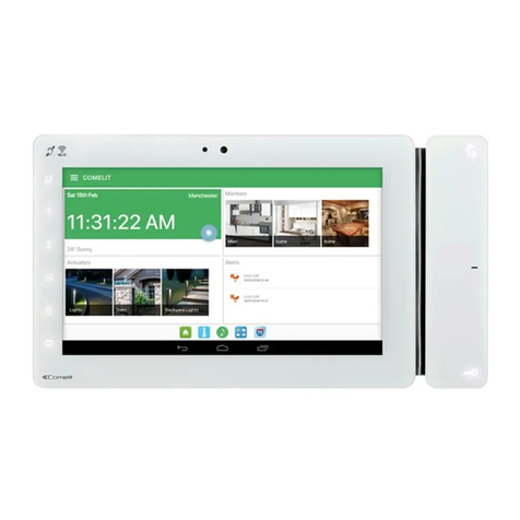
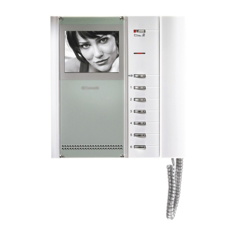
  9. Comelit MAXI SBC User manual

Comelit MAXI SBC User manual

This manual suits for next models

2

Other Comelit Intercom System manuals

Comelit VEDO5TPRW User manual

Comelit

Comelit VEDO5TPRW User manual

Comelit KCA2071 User manual

Comelit

Comelit KCA2071 User manual

Comelit 1441A User guide

Comelit

Comelit 1441A User guide

Comelit Magis  6402E User manual

Comelit

Comelit Magis 6402E User manual

Comelit 2719W User manual

Comelit

Comelit 2719W User manual

Comelit 316 Sense User manual

Comelit

Comelit 316 Sense User manual

Comelit KAE5062A User manual

Comelit

Comelit KAE5062A User manual

Comelit Simplebus FT/SB/06 User manual

Comelit

Comelit Simplebus FT/SB/06 User manual

Comelit 2703U User manual

Comelit

Comelit 2703U User manual

Comelit 6701 User manual

Comelit

Comelit 6701 User manual

Comelit Easycom ViP internal unit User manual

Comelit

Comelit Easycom ViP internal unit User manual

Comelit FT SB2 24 Operating and maintenance instructions

Comelit

Comelit FT SB2 24 Operating and maintenance instructions

Comelit AD5001 User manual

Comelit

Comelit AD5001 User manual

Comelit Ciao CA5100A User manual

Comelit

Comelit Ciao CA5100A User manual

Comelit 8471MB User manual

Comelit

Comelit 8471MB User manual

Comelit 2702W User manual

Comelit

Comelit 2702W User manual

Comelit Architectus Pro SBTop Series User manual

Comelit

Comelit Architectus Pro SBTop Series User manual

Comelit 8171IMC User manual

Comelit

Comelit 8171IMC User manual

Comelit 6602W User manual

Comelit

Comelit 6602W User manual

Comelit Diva series User manual

Comelit

Comelit Diva series User manual

Comelit Planux 8172IP User manual

Comelit

Comelit Planux 8172IP User manual

Comelit Switch Series User manual

Comelit

Comelit Switch Series User manual

Comelit Mini 6701 User manual

Comelit

Comelit Mini 6701 User manual

Comelit 6801W User manual

Comelit

Comelit 6801W User manual

Popular Intercom System manuals by other brands

Videx VRDK1 (25H) Technical manual

Videx

Videx VRDK1 (25H) Technical manual

Auta COMPACT VISUALTECH manual

Auta

Auta COMPACT VISUALTECH manual

Aiphone LC-10S instructions

Aiphone

Aiphone LC-10S instructions

Aiphone PD-1 instructions

Aiphone

Aiphone PD-1 instructions

Aiphone JF-DVF-HID-I instructions

Aiphone

Aiphone JF-DVF-HID-I instructions

MGL Avionics V16 manual

MGL Avionics

MGL Avionics V16 manual

SSS Siedle BVI 750-0 Installation & programming

SSS Siedle

SSS Siedle BVI 750-0 Installation & programming

urmet domus AIKO 1716/1 quick start guide

urmet domus

urmet domus AIKO 1716/1 quick start guide

urmet domus IPerVoice 1039 Installation

urmet domus

urmet domus IPerVoice 1039 Installation

Alpha Communications STR QwikBus TT33-2 Installation, programming, and  user's manual

Alpha Communications

Alpha Communications STR QwikBus TT33-2 Installation, programming, and user's manual

Monacor ICM-20H instruction manual

Monacor

Monacor ICM-20H instruction manual

Logenex A202CR Installation & programming

Logenex

Logenex A202CR Installation & programming

Quantum QR5 Installation and programming manual

Quantum

Quantum QR5 Installation and programming manual

EVGA XR1 quick guide

EVGA

EVGA XR1 quick guide

CyberData 011211 series Installation quick reference

CyberData

CyberData 011211 series Installation quick reference

Vidos duo M1021 user manual

Vidos

Vidos duo M1021 user manual

Savant DOR-SMS-00 Deployment guide

Savant

Savant DOR-SMS-00 Deployment guide

SSS Siedle BTSV 850-03 operating instructions

SSS Siedle

SSS Siedle BTSV 850-03 operating instructions

manuals.online logo
manuals.online logoBrands
  • About & Mission
  • Contact us
  • Privacy Policy
  • Terms and Conditions

Copyright 2025 Manuals.Online. All Rights Reserved.

IT
MANUALE
TECNICO
EN
TECHNICAL
MANUAL
FR
MANUEL
TECHNIQUE
NL
TECHNISCHE
HANDLEIDING
DE
TECHNISCHES
HANDBUCH
ES
MANUAL
TÉCNICO
PT
MANUAL
TÉCNICO
Manuale tecnico monitor colori 7” MAXI SBC Art. 6801W (/BM)
Technical manual for 7” MAXI SBC colour monitor Art. 6801W (/BM)
Manuel technique moniteur couleurs 7 pouces MAXI SBC Art. 6801W (/BM)
Technische handleiding 7” kleurenmonitor MAXI SBC Art. 6801W (/BM)
Technisches Handbuch 7-Zoll-Farbmonitor MAXI SBC Art. 6801W (/BM)
Manual técnico del monitor en color 7” MAXI SBC art. 6801W (/BM)
Manual técnico do monitor a cores 7” MAXI SBC art. 6801W (/BM)
2
EN
FR
NL
PT
DE
ES
IT
EN
FR
NL
DE
ES
PT
Avvertenze
• Effettuare l’installazione seguendo scrupolosamente le istruzioni fornite dal costruttore ed in conformità alle norme vigenti.
• Tutti gli apparecchi devono essere destinati esclusivamente all’uso per cui sono stati concepiti. Comelit Group S.p.A. declina ogni responsabilità per un utilizzo improprio degli apparecchi, per modiche
åTutti i prodotti sono conformi alle prescrizioni delle direttive 2006/95/CE (che sostituisce la direttiva 73/23/CEE e successivi emendamenti) e ciò è attestato dalla presenza della marcatura CE sugli stessi.
• Evitare di porre i li di montante in prossimità di cavi di alimentazione (230/400V).
• Gli interventi di installazione, montaggio e assistenza agli apparecchi elettrici devono essere eseguiti esclusivamente da elettricisti specializzati.
• Togliere l’alimentazione prima di effettuare qualsiasi manutenzione.
IT
Attivazione tasti a soramento.
`Toccare per attivare i tasti funzione.
EN Warning
• Install the equipment by carefully following the instructions given by the manufacturer and in compliance with the standards in force.
• All the equipment must only be used for the purpose it was designed for. Comelit Group S.p.A. declines any responsibility for improper use of the apparatus, for any alterations made by others for any
reason or for the use of non-original accessories or materials.
• All the products comply with the requirements of Directive 2006/95/EC (which replaces Directive 73/23/EEC and subsequent amendments), as certied by the CE mark they carry.
• Do not route the riser wires in proximity to power supply cables (230/400V).
• Installation, mounting and assistance procedures for electrical devices must only be performed by specialised electricians.
• Cut off the power supply before carrying out any maintenance work.
Soft-touch key activation.
`Touch to activate the function keys.
FR Avertissement
• Effectuer l'installation en suivant scrupuleusement les instructions fournies par le constructeur et conformément aux normes en vigueur.
• Tous les appareils doivent être strictement destinés à l'emploi pour lequel ils ont été conçus. La société Comelit Group S.p.A. décline toute responsabilité en cas de mauvais usage des appareils, pour
des modications effectuées par d’autres personnes pour n’importe quelle raison et pour l'utilisation d’accessoires et matériaux non d'origine.
• Tous les produits sont conformes aux prescriptions de la directive 2006/95/CE (qui remplace la directive 73/23/CEE et amendements successifs). L'application du marquage CE atteste cette conformité.
• Éviter de placer les ls de montant à proximité des câbles d'alimentation (230/400V).
• Les interventions d'installation, de montage et d'assistance aux appareils électriques sont réservées à des électriciens spécialisés.
• Couper l'alimentation avant d'effectuer toute opération d'entretien.
Activation touches à efeurement.
`Effleurer pour activer les touches de fonction.
NL Waarschuwingen
• Voer de installatiewerkzaamheden zorgvuldig uit volgens de door de fabrikant gegeven instructies en met inachtneming van de geldende normen.
• Alle componenten mogen alleen gebruikt worden voor de doeleinden waarvoor ze zijn ontworpen. Comelit Group S.p.A. is niet verantwoordelijk voor oneigenlijk gebruik van de apparatuur, voor
wijzigingen die om welke reden dan ook door derden zijn aangebracht, en voor het gebruik van accessoires en materialen die niet door de fabrikant zijn aangeleverd.
• Alle producten voldoen aan de eisen van de richtlijn 2006/95/EG (die de richtlijn 73/23/EEG en latere wijzigingen vervangt). Hiervan getuigt het CE-label op de producten.
• Monteer de aders van de stamleiding niet in de nabijheid van voedingskabels (230/400V).
• De installatie-, montage- en servicewerkzaamheden aan de elektrische apparaten mogen uitsluitend door gespecialiseerde elektriciens worden verricht.
• Sluit de voeding af, voordat u onderhoudswerkzaamheden uitvoert.
Activering aanraaktoetsen.
`Raak aan om de functietoetsen te activeren.
DE
Tastenaktivierung durch Berührung.
Wichtige Hinweise
• Der Einbau muss strikt nach Herstelleranweisungen und unter Einhaltung der einschlägigen Vorschriften erfolgen.
• Alle Geräte dürfen nur für den Zweck eingesetzt werden, für den sie entwickelt worden sind. Comelit Group S.p.A. übernimmt keine Haftung für unsachgemäßen Gebrauch der Geräte, für durch Dritte
vorgenommene Änderungen oder die Verwendung von Nicht-Original-Zubehör und -Ersatzteilen.
• Alle unsere Produkte erfüllen die Anforderungen der Richtlinie 2006/95/EG (ersetzt Richtlinie 73/23/EWG und nachfolgende Ergänzungen), was durch die CE-Kennzeichnung der Geräte bestätigt wird.
• Die Kabel der Steigleitung nicht in Nähe der Stromkabel (230/400 V) verlegen.
• Installation, Einbau und Wartung der elektrischen Geräte dürfen nur von einem Elektrofachmann ausgeführt werden.
• Vor Wartungseingriffen immer die Stromversorgung unterbrechen.
`Die Funktionstasten berühren, um sie zu aktivieren.
ES Advertencias
• La instalación se ha de efectuar en conformidad con las normas vigentes, siguiendo atentamente las instrucciones suministradas por el fabricante.
• Todos los aparatos deben destinarse exclusivamente al uso para el cual han sido construidos. Comelit Group S.p.A. declina toda responsabilidad por el uso impropio de los aparatos, por cambios
efectuados por terceros por cualquier motivo o nalidad y por el uso de accesorios y materiales no originales.
• Todos los productos son conformes a los requisitos de la Directiva 2006/95/CE (que sustituye la Directiva 73/23/CEE y sucesivas enmiendas) como demuestra la presencia de la marca CE en ellos.
• No poner los cables de la columna montante cerca de los cables de alimentación (230/400V).
• La instalación, el montaje y el mantenimiento de los aparatos eléctricos deben ser efectuados exclusivamente por electricistas especializados.
• Antes de efectuar cualquier operación de mantenimiento hay que cortar la alimentación.
Activación de las teclas táctiles.
`Tocar para activar las teclas de función.
PT Avisos
• Instalar o equipamento cuidadosamente, seguindo as instruções dadas pelo fabricante e em conformidade com a legislação em vigor.
• Todos os aparelhos devem ser exclusivamente destinados ao uso para o qual foram concebidos. Comelit Group S.p.A. declina qualquer responsabilidade pelo uso impróprio do equipamento, quaisquer
modicações efectuadas por qualquer motivo sem autorização prévia, como também pelo uso de acessórios e materiais que não tenham sido originariamente fornecidas pela Comelit Group S.p.A.
• Todos os produtos estão em conformidade com os requisitos das directivas 2006/95/CE (que substituem as directivas 73/23/CEE e as alterações subsequentes). A prova é a marca CE nos produtos.
• Evitar colocar os os da coluna na proximidade de cabos de alimentação (230/400 V).
• As intervenções de instalação, montagem e assistência a aparelhos eléctricos devem ser realizadas exclusivamente por electricistas especializados.
• Cortar a alimentação eléctrica antes de realizar qualquer tipo de manutenção.
Activação de teclas tácteis.
`Tocar para activar as teclas de funções.
3
NL
FR
EN
DE
ES
PT
1 2 IT
Tasto / LED fonica
sso = fonica aperta / funzione mani libere
lampeggio continuo = chiamata ricevuta
Tasto / LED apriporta
1 lampeggio = conferma apriporta
4 lampeggi = successo programmazione
10 lampeggi = errore programmazione
lampeggio continuo = porta aperta
Tasti 1-2-3-4 (programmabili)
Tasto autoaccensione (programmabile)
Tasto privacy / LED privacy - dottore
4 lampeggi = dispositivo occupato
lampeggio lento = programmazione
3 lampeggi (ogni 5 s.) = funz. dottore attiva
sso = funz. privacy attiva
Tasto volume fonica
Tasto volume suoneria
Tasto aumenta/diminuisci valore
Tasto contrasto
Tasto luminosità
1. Schermo LCD colori 7”
2. Microfono
Monitor Maxi 7" SBC Art. 6801W (/BM)
EN
7" Maxi SBC monitor Art. 6801W (/BM)
Audio key/LED
steady = audio enabled/hands-free function
continuous ashing = call received
Lock-release key/LED
1 ash = conrm lock-release
4 ashes = programming successful
10 ashes = programming error
continuous ashing = door open
Keys 1-2-3-4 (programmable)
Self-ignition key (programmable)
Privacy key/Privacy LED - Doctor
4 ashes = device engaged
slow ashing = programming
3 ashes (every 5 s.) = Doctor function enabled
steady = privacy function enabled
Audio volume key
Ringtone volume key
Value 'Up/Down' key
Contrast key
Brightness key
1. 7” colour LCD screen
2. Microphone FR
Moniteur Maxi 7 pouces SBC Art. 6801W (/BM)
Touche/led phonie
allumée = phonie ouverte/fonction mains libres
clignotement constant = appel reçu
Touche/led ouvre-porte
1 clignotement = conrmation ouvre-porte
4 clignotements = programmation réussie
10 clignotements = erreur de programmation
clignotement constant = porte ouverte
Touches 1-2-3-4 (programmables)
Touche auto-allumage (programmable)
Touche privacy / led coupure sonnerie
4 clignotements = dispositif occupé
clignotement lent = programmation
3 clignotements (toutes les 5 s) = fonction
docteur ON
allumée = fonction privacy ON
Touche volume phonie
Touche volume sonnerie
Touche d'augmentation/diminution valeur
Touche contraste
Touche luminosité
1. Écran LCD couleurs 7pouces
2. Micro NL
Monitor Maxi 7" SBC Art. 6801W (/BM)
Audiotoets/-LED
brandt = audio open / handsfree-functie
continu knipperend = oproep ontvangen
Deurslotbedieningstoets/-LED
knippert 1 maal = bevestig deurslotbediening
knippert 4 maal = programmering geslaagd
knippert 10 maal = fout in programmering
knippert continu = deur open
Toetsen 1-2-3-4 (programmeerbaar)
Beeldoproeptoets (programmeerbaar)
Privacytoets / LED privacy + artsfunctie
knippert 4 maal = toestel bezet
knippert langzaam = programmering
knippert 3 maal (per 5 s.) = artsfunctie actief
brandt = privacy-functie actief
Toets audiovolume
Volumetoets oproeptoon
Toets voor waarde verhogen/verlagen
Contrasttoets
Helderheidstoets
1. LCD-kleurenscherm 7”
2. Microfoon
DE
7-Zoll-Farbmonitor Maxi SBC Art. 6801W (/BM)
Taste / LED Sprechtaste
leuchtet = Sprechverbindung besteht / Freisprechfunktion
Dauerblinken = Ruf empfangen
Taste / LED Türöffner
1 Blitz = Bestätigung Türöffner
4 Blitze = Programmierung erfolgreich
10 Blitze = Programmierfehler
Dauerblinken: Tür geöffnet
Tasten 1-2-3-4 (programmierbar)
Taste Selbsteinschaltung (programmierbar)
Taste Mithörsperre / LED Mithörsperre - Arzt
4 Blitze = Gerät besetzt
Langsames Blinken = Programmierung
3 Blitze (alle 5 s) = Arztfunktion aktiv
Leuchtet = Funktion Mithörsperre aktiv
Lautstärke Sprechtaste
Taste Lautstärke Klingelton
Taste Werterhöhung/Wertverminderung
Kontrasttaste
Helligkeitstaste
1. LCD-Farbbildschirm 7”
2. Mikrofon ES
Monitor Maxi 7" SBC art. 6801W (/BM)
Tecla / led del audio
jo = audio activado / función manos libres
parpadeo continuo = llamada recibida
Tecla / led del abrepuertas
1 parpadeo = conrmación abrepuertas
4 parpadeos = programación efectuada
correctamente
10 parpadeos = error en la programación
parpadeo continuo = puerta abierta
Teclas 1-2-3-4 (programables)
Tecla de autoencendido (programable)
Tecla Privacidad / led Privacidad - Doctor
4 parpadeos = dispositivo ocupado
parpadeo lento = programación
3 parpadeos (cada 5 s) = función Doctor activada
jo = función Privacidad activada
Tecla del volumen del audio
Tecla del volumen del tono de llamada
Tecla para aumentar/disminuir el valor
Tecla de contraste
Tecla de brillo
1. Pantalla LCD en color 7”
2. Micrófono PT
Monitor Maxi 7” SBC art. 6801W (/BM)
Tecla/Luz indicadora som
Fixa = som activado/função mãos livres
Pisca continuamente = chamada recebida
Tecla/Luz indicadora abertura da porta
Pisca 1 vez = conrmação da abertura da porta
Pisca 4 vezes = programação bem-sucedida
Pisca 10 vezes = erro de programação
Pisca continuamente = porta aberta
Teclas 1-2-3-4 (programáveis)
Tecla acendimento automático (programável)
Tecla privacidade/Luz indicadora privacidade - médico
Pisca 4 vezes = dispositivo ocupado
Pisca lentamente = programação
Pisca 3 vezes (a cada 5 seg.) = função médico activada
Fixa = função privacidade activada
Tecla volume do som
Tecla volume da campainha
Tecla aumentar/diminuir valor
Tecla contraste
Tecla luminosidade
1. Ecrã LCD cores 7”
2. Microfone
4
12
3
4
5
6
IT
1
CV6
posizione A = contatto IN1-IN2 > LED (di default)
posizione B = contatto CFP2-IN1 > ALLARME/APRIPORTA/ATTUATORE
2 CV1 CV2 Jumper alimentazione separata
3 CV5 Jumper chiusura video
4 S2 Micro-interruttori per programmazioni speciali
DIP 1-2-3-4 per programmazione funzioni pulsanti
DIP 5-6 accesso programmazioni
DIP 7 per gestione tensione di alimentazione
(vedi schemi e varianti) default = OFF
DIP 8: ON staffa secondaria / OFF staffa principale (default)
5 Morsettiera per connessione impianto:
CFP1 CFP2 Ingresso chiamata fuori porta
S+ S- Morsetti per suoneria supplementare
IN1 IN2 Morsetti ingresso (programmabile)
- + Morsetti per alimentazione
LLMorsetti di connessione linea Bus
6 S1 Micro-interruttori per programmazione codice utente
EN
1 CV6
position A = contact IN1-IN2 > LED (default)
position B = contact CFP2-IN1 > ALARM/LOCK-RELEASE/ACTUATOR
2 CV1 CV2 Jumper for separate power supply
3 CV5 Jumper for video closure
4 S2 Micro-switches for programming keys and functions
DIP 1-2-3-4 for key function programming
DIP 5-6 access to programming
DIP 7 for power supply voltage management (see diagrams and variants),
default = OFF
DIP 8: ON
secondary backplate / OFF
main backplate (default)
5 Terminal block for system connection:
CFP1 CFP2Outside door call input
S+ S- Terminals for additional ringtone output
IN1 IN2 Input terminals (programmable)
- + Power supply terminals
L L
Bus line connection terminals
6 S1
User code programming microswitches
FR
1
CV6
position A = contact IN1-IN2 > LED (par défaut)
position B = contact CFP2-IN1 > ALARME/OUVRE-PORTE/ACTIONNEUR
2 CV1 CV2 Cavalier d’alimentation séparée
3 CV5 Cavalier de débranchement vidéo
4 S2 DIP switches pour programmations spéciales
DIP 1-2-3-4 de programmation des fonctions des boutons
DIP 5-6 accès à la programmation
DIP 7 de gestion de la tension d’alimentation (voir schémas et variantes)
défaut = OFF
DIP 8 : ON
étrier secondaire / OFF
étrier principal (défaut)
5 Bornes de raccordement de l’installation :
CFP1 CFP2 Entrée de l'appel extérieur
S+ S-
Bornes pour sonnerie supplémentaire
IN1 IN2 Bornes entrée (programmable)
- + Bornes pour alimentation
L L
Bornes de connexion ligne Bus
6 S1
DIP switches pour la programmation du code d’appel
NL
1
CV6
stand A = contact IN1-IN2 > LED (default)
stand B = contact CFP2-IN1 > ALARM/DEURSLOTBEDIENING/RELAIS
2 CV1 CV2 Jumper aparte voeding
3 CV5 Jumper voor afsluiten van het videosignaal
4 S2 Microschakelaars voor speciale programmeringen
DIP 1-2-3-4 voor het programmeren van de functies van de drukknoppen
DIP 5-6 toegang tot de programmeringen
DIP 7 voor beheer voedingsspanning
(zie schema’s en varianten) default = OFF
DIP 8: ON
secundaire muurplaat / OFF
hoofdmuurplaat (default)
5 Klemmenblok voor de installatie:
CFP1 CFP2 Ingang etagebel
S+ S- Aansluitklemmen voor extra bel
IN1 IN2 Ingangsklemmen (programmeerbaar)
- + Voedingsklemmen
L L
Klemmen voor aansluiting buslijn
6 S1
Microschakelaars voor het programmeren van de gebruikerscode
DE
1
CV6
Position A = Kontakt IN1-IN2 > LED (Werkeinstellung)
Position B = Kontakt CFP2-IN1 > ALARM/TÜRÖFFNER/RELAIS
2 CV1 CV2 Steckbrücke für separate Stromversorgung
3 CV5 Steckbrücke zum Schließen des Videosignals
4 S2 Mikroschalter für Spezialprogrammierungen
DIP-Schalter 1-2-3-4 für die Programmierung der Tastenfunktionen
DIP 5-6 Zugriff auf die Programmierungen
DIP 7 für die Einstellung der Versorgungsspannung (siehe Schaltpläne und
Varianten) Werkeinstellung = OFF
DIP 8: ON
zusätzliche Grundplatte / OFF
Hauptgrundplatte (Standard)
5 Klemmleiste für den Anschluss an die Anlage:
CFP1 CFP2 Eingang Etagenruf
S+ S-
Klemmen Zusatz-Läutewerk
IN1 IN2 Klemmen Eingang (programmierbar)
- + Klemmen für Stromversorgung
L L
Anschlussklemmen Busleitung
6 S1
Mikroschalter für die Programmierung des Benutzercodes
ES
1
CV6
posición A = contacto IN1-IN2 > LED (predenido)
posición B = contacto CFP2-IN1 > ALARMA/ABREPUERTAS/ACTUADOR
2 CV1 CV2 Puente para la alimentación separada
3 CV5 Puente para el cierre del vídeo
4 S2 Microinterruptores para programaciones especiales
DIP 1-2-3-4 para programar las funciones de los pulsadores
DIP 5-6 para acceder a la programación
DIP 7 para controlar la tensión de alimentación
(véanse los esquemas y las variantes) predenido = OFF
DIP 8: ON
placa soporte secundaria / OFF
placa soporte principal (predenido)
5 Regleta de conexiones para la instalación:
CFP1 CFP2 Entrada para llamada desde el timbre de planta
S+ S- Bornes para timbre adicional
IN1 IN2 Bornes entrada (programable)
- + Bornes para alimentación
L L
Bornes de conexión de la línea Bus
6 S1
Microinterruptores para programar el código de usuario
PT
1
CV6
posição A = contacto IN1-IN2 > LUZ INDICADORA (predenição)
posição B = contacto CFP2-IN1 > ALARME/ABERTURA DA PORTA/ACTUADOR
2 CV1 CV2 Comutador de derivação alimentação separada
3 CV5 Comutador de derivação fecho vídeo
4 S2 Microinterruptores para programações especiais
DIP 1-2-3-4 Para programar as funções dos botões
DIP 5-6 Acesso às programações
DIP 7 Para gerir a alimentação eléctrica
(consultar esquemas e variantes) predenição = OFF
DIP 8: ON
suporte secundário/OFF
suporte principal (predenição)
5 Bateria de bornes de ligação da instalação:
CFP1 CFP2 Entrada para chamada campainha externa
S+ S- Bornes para campainha adicional
IN1 IN2 Bornes entrada (programável)
- + Bornes para alimentação
L L
Bornes para a ligação à linha bus
6 S1
Microinterruptores para programar o código de utilizador
5
Montaggio monitor Maxi 7" SBC su scatola ad incasso Art. 6817
EN
Mounting the 7" MAXI SBC monitor on ush-mounted box Art. 6817
FR Montage moniteur Maxi 7 pouces SBC sur boîtier à encastrer Art. 6817
NL Montage 7" monitor Maxi SBC op inbouwdoos art. 6817
DE Montage des 7-Zoll-Monitors Maxi SBC in Unterputzgehäuse Art. 6817
ES Montaje del monitor Maxi 7" SBC en caja de empotrar art. 6817
ALTO
UP
HAUT
OBEN
2
1
CLACK ! 2
3
6
9
160 cm
130 cm
Lmax = 10 cm
Lmin = 6 cm
1
2
2
5
8
223 mm
124 mm
3
1
5
7
9
4
2
6
8
1
2
1
2
1
4
7
SMONTAGGIO / DISASSEMBLY
PT Montagem do monitor Maxi 7” SBC na caixa de embutir art. 6817
6
12
Lmax = 7 cm
Lmin = 6,5 cm
4A
160 cm
130 cm
1
2
2
1
CLACK ! 2
2
6
1
2
2
1
2
1
CLACK ! 2
3B
3A
5A
SMONTAGGIO / DISASSEMBLY
3C
con/with Art.6820*
con/with Art.6820* con/with Art.6820*
* Art. 6820 (opzionale/optional)
223 mm
124 mm
1
Montaggio a parete (Art. 6820) / su scatola serie 503 / scatola tonda
EN
Wall-mounting (Art. 6820) / on 503 series box/round box
FR
Montage en saillie (Art. 6820) / sur boîtier série 503 / boîtier rond
NL
Montage aan de wand (art.
6820
) / op inbouwdoos serie 503 / ronde doos
DE
Einbau: Aufputz (Art. 6820) / in Gehäuse Serie 503 / in rundem Gehäuse
ES
Montaje de supercie (art. 6820) / en caja serie 503 / caja redonda
PT
Montagem na parede (art. 6820)/na caixa série 503/caixa redonda
7
Legenda Legend Légende Legenda Legende Leyenda Legenda
Apriporta Lock-release Ouvre-porte
Deurslot bediening
Türöffner Abrepuertas Abertura da porta
Fonica Audio Phonie
Audio
Sprechverbindung Audio Som
ACT Attuatore Actuator Actionneur
Relais
Aktor Actuador Actuador
AI Autoaccensione
`Pressione prolungata per attivare/
disattivare la funzione.
Self-ignition
`Press and hold to enable/
disable the function.
Auto-allumage
`Appui prolongé pour activer/désactiver
la fonction.
Beeldoproep
`Lang indrukken om de functie te
activeren/deactiveren.
Selbsteinschaltung
`Langer Tastendruck, um die Funktion
zu aktivieren/deaktivieren.
Autoencendido
`Presión prolongada para activar/
desactivar la función
Acendimento automático
`Premir prolongadamente para
activar/desactivar a função.
CCP*Chiamata a centralino
principale*Main switchboard call*Appel au standard principal *
Oproep naar
hoofdportierscentrale*
Ruf an Hauptzentrale*Llamada a la centralita
principal*
Chamada a central
principal*
CCS*Chiamata a centralino
secondario*
Secondary switchboard
call*
Appel au standard
secondaire*
Oproep naar secundaire
portiercentrale*
Ruf an
Nebenzentrale*
Llamada a la centralita
secundaria*
Chamada a central
secundária*
KChiamata citofono
guardiano
Caretaker door-entry
phone call Appel combiné audio gardien
Deurtelefoonoproep bewaker
Sprechverbindung
Wachmann
Llamada al telefonillo del
vigilante
Chamada a
intercomunicador do
vigilante
DDottore Doctor Docteur
Arts
Arztruf Doctor Médico
PAN*Panico*Panic*Panique*
Paniek*
Panik*Pánico*Emergência*
INT
Intercomunicante
programmabile
generale
o selettivo
- di serie chiamata generale
interna per KIT e Simplebus
Top
General or selective
programmable
intercom
- general internal call
as standard for KIT and
Simplebus Top
Appel intercommunicant
programmable général ou
sélectif
- de série, appel général interne
pour KIT et Simplebus Top
Programmeerbare intercom
algemeen of selectief
- standaard algemene
interne oproep voor KIT en
Simplebus Top
Internruf programmierbar
allgemein oder selektiv
- Serienmäßig allgemeiner
Internruf für KIT und Simplebus
Top
Intercomunicante
programable
general o
selectivo
- llamada general interna de
serie para KIT y Simplebus
Top
Intercomunicação
programável
geral ou
selectiva
- de série chamada geral
interna para KIT e Simplebus
Top
INTb Intercomunicante bifamiliare
- solo per KIT
Two-family intercom
- for KIT only
Appel intercommunicant deux
appels
- uniquement pour KIT
Tweevoudige intercom
- alleen voor KIT
Intenrruf Zweifamilienhaus
- nur für KIT
Intercomunicante
bifamiliar
- solo para KIT
Intercomunicação bifamiliar
- só para KIT
NULL Nessuna funzione No function Aucune fonction
Geen functie
Keine Funktion Ninguna función Nenhuma função
PROG
Funzioni programmate, vedi
pag. 8-11-13.
In questa impostazione dei
dip i pulsanti gestiscono le
funzioni programmate.
I pulsanti NON programmati
gestiscono le funzioni riferite
alla riga 0000
Programmed functions, see
pages 8-11-13.
With these DIP-switch
settings, the buttons
manage the programmed
functions.
The NON-programmed
buttons control the functions
referred to on line 0000
Fonctions programmées, voir
pages 8-11-13.
Lorsque les dip sont ainsi
congurés, les boutons
gouvernent les fonctions
programmées.
Les boutons NON programmés
commandent les fonctions
signalées à la ligne 0000
Geprogrammeerde functies, zie
pag. 8-11-13.
Bij deze instelling van
de dipswitches beheren
de drukknoppen de
geprogrammeerde functies.
De NIET-geprogrammeerde
drukknoppen beheren de functies
die verwijzen naar regel 0000
Programmierte Funktionen, siehe
Seiten 8-11-13.
Bei dieser Einstellung der
DIP-Schalter sind die Tasten für
die programmierten Funktionen
zuständig.
Die NICHT programmierten Tasten
betätigen die Funktionen der
Zeile 0000
Funciones programadas,
véanse págs. 8-11-13.
Congurando los DIP-
switches de esta manera,
los pulsadores controlan las
funciones programadas.
Los pulsadores NO
programados controlan
las funciones referidas a la
línea 0000
Funções programadas,
consultar pág. 8-11-13.
Nesta conguração dos dips,
os botões gerem as funções
programadas.
Os botões NÃO programados
gerem as funções indicadas na
linha 0000
* non utilizzabile su
impianti kit
* cannot be used in kit
systems
* non utilisable sur les
systèmes kit
* kan niet worden gebruikt
op kit-systemen
* nicht verwendbar bei
Anlagen KIT
* No se puede utilizar en
instalaciones con kit
* não utilizável em siste-
mas kit
DIP S2
DIP 1 DIP 2 DIP 3 DIP 4 P1 P2 P3 P4
0 0 0 0 AI CCS ACT D PAN
1 0 0 0 AI ACT INT INTb D
0 1 0 0 AI INT INTb ACT CCS
1 1 0 0 CCS ACT CCP PAN K
0 0 1 0 ACT ACT ACT ACT ACT ACT
1 0 1 0 ACT INT CCS CCP INTb
0 1 1 0 D AI K CCS CCP
1 1 1 0 INT INTb AI INT PAN
0 0 0 1 PAN CCS D AI INT
1 0 0 1 CCS K PAN CCP AI
0 1 0 1 K CCP PAN ACT INT
1 1 0 1 CCP PAN CCS K ACT
0 0 1 1 INTb D INT ACT AI
1 0 1 1 INT INT INT INT INT
0 1 1 1 NULL NULL NULL NULL NULL NULL NULL
1 1 1 1 PROG
*
*default
IT
EN
FR
DE
ES
PT
NL
4 sec.
Congurazioni pulsanti.
IT
Abilitazione (ON) / disabilitazione (OFF) risposta automatica.
»ON : il led fonica resta acceso
»OFF: il led fonica resta spento
• ON:
• OFF: BEEP
EN
EN
Button congurations.
Enabling (ON)/disabling (OFF) automatic response.
»ON: the audio LED remains lit
»OFF: the audio LED remains unlit
FR
FR
Conguration boutons.
Validation (ON) /invalidation (OFF) réponse automatique.
»ON : la led phonie reste allumée
»OFF : la led phonie reste éteinte
NL
NL
Conguratie drukknoppen.
Inschakeling (ON) / uitschakeling (OFF) automatische beantwoording.
»ON: de audio-LED blijft aan
»OFF: de audio-LED blijft uit
DE
DE
Tastenkongurationen
Aktivierung (ON) / Deaktivierung (OFF) der Antwortautomatik.
»ON: Die LED der Sprechverbindung bleibt eingeschaltet
»OFF: Die LED der Sprechverbindung bleibt ausgeschaltet
ES
ES
Conguración de los pulsadores.
Habilitación (ON) / inhabilitación (OFF) de la respuesta automática.
»ON: el led de audio permanece encendido
»OFF: el led de audio permanece apagado
PT
PT
Conguração dos botões.
»ON: a luz indicadora do som permanece acesa
»OFF: a luz indicadora do som permanece desligada
Activação (ON)/desactivação (OFF) da resposta automática.
8
DIP S2 DIP S1
DIP 1 DIP 2 DIP 3 DIP 4 P1 P2 P3 P4
INDIRIZZO
ADDRESS
ADRESSE
ADRES
ADRESSE
DIRECCIÓN
ENDEREÇO
0000 ACT
1000 ACT
0100 ACT
1100 ACT
0010 ACT ACT ACT ACT ACT ACT
1010 ACT
0110
1110
0001
1001
0101 ACT
1101 ACT
0011 ACT
1011
0111
1111 PROG
LED_1
LED2
LED_2
x4
Avvertenze generali programmazione pulsanti.
Nel caso le congurazioni pulsanti predenite (vedi tabella pag. 7) non soddisno
le necessità è possibile programmare diversamente i pulsanti, abbinando funzioni
speciche ad ogni tasto, secondo le procedure e le combinazioni riportate a seguire.
Al termine della programmazione posizionare i DIP 1-2-3-4 di S2 in combina-
zione 1111 (settaggio PROG nelle tabelle di congurazione pag. 8, 11, 13). In questa
impostazione dei dip i pulsanti gestiscono le funzioni programmate; i pulsanti NON
programmati gestiscono le funzioni riferite alla riga 0000 (vedi tabella pag. 7).
Ripristinare su S1 l'impostazione del codice utente, vedi tabella A pag. 24.
Programmazioni pulsanti per attuatore generico o indirizzato.
Esempio:
su monitor con codice utente 5 programmazione P1= attuatore ge-
nerico, = attuatore indirizzato a codice 125
1. Posizionare DIP 5-6 di S2 in combinazione 01
»il led 1 lampeggia
2. Consultare la tabella pag. 8 e scegliere una combinazione in cui
compare la funzione attuatore (ACT) per i pulsanti che si intendono
programmare.
ES: per P1= attuatore generico impostare DIP 1-2-3-4 di S2 in
combinazione 1000 o 1100 o 0010 (P1=ACT), impostare DIP di S1 in
combinazione 11111111, passare al punto 3
ES: per = attuatore indirizzato a codice 125 impostare DIP 1-2-3-4
di S2 in combinazione 0010 o 1010 ( =ACT), impostare S1 con indi-
rizzo 125 secondo tabella A pag. 24, passare al punto 3
3. Premere e rilasciare il pulsante a cui si vuole associare la funzione
»il led 2 lampeggia x 4 volte
»tono di conferma
4. Per uscire dalla programmazione posizionare i DIP 5-6 di S2 in
combinazione 00
» il led 1 si spegne
5. Al termine della programmazione posizionare i DIP 1-2-3-4 di
S2 in combinazione 1111. Ripristinare su S1 l'impostazione del
codice utente, vedi tabella A pag. 24.
General button programming warnings.
If the default button congurations (see table on page 7) do not meet your
requirements, you can programme the buttons differently by assigning specic
functions to each key, according to the procedures and combinations shown below.
On completion of programming, set S2 DIP switches 1-2-3-4 to the combina-
tion 1111 (PROG setting in the conguration tables on pages 8, 11, 13). In this
DIP-switch setting, the buttons control the programmed functions; the NON-pro-
grammed buttons control the functions referred to on line 0000 (see table on
page 7). Restore the user code setting on S1, see table A on page 24.
EN
Programming buttons for generic or coded actuator.
Recommandations générales pour la programmation des boutons.
Au cas où les congurations prédénies des boutons (voir tableau page 7)
ne s’avéreraient pas sufsantes pour les situations prévues, il est possible de
programmer les boutons différemment, en associant des fonctions spéciques
à chaque touche, selon les procédures et les combinaisons indiquées ci-après.
Une fois la programmation terminée, placer les DIP 1-2-3-4 de S2 en com-
binaison 1111 (réglage PROG dans les tableaux de conguration pages 8, 11,
13). Lorsque les dip sont ainsi congurés, les boutons gouvernent les fonctions
programmées ; les boutons NON programmés commandent les fonctions
signalées à la ligne 0000 (voir tableau page 7). Rétablir sur S1 la congura-
tion du code résident, voir tableau A page 24.
FR Programmation des boutons pour actionneur générique ou à code.
Algemene waarschuwingen voor de programmering van de drukknoppen.
11, 13). Met deze instelling van de dipswitches beheren de drukknoppen de ge-
programmeerde functies; de NIET-geprogrammeerde knoppen beheren de
functies die vermeld staan op de regel 0000 (zie de tabel op pag. 7). Herstel
de instelling van de gebruikerscode op S1, zie tabel A op pag. 24.
Als de voorgedenieerde drukknopconguraties (zie de tabel op pag. 7) niet
aan de behoeften voldoen, is het mogelijk de drukknoppen anders te program-
meren door met iedere toets specieke functies te combineren, volgens de
procedures en de combinaties die hieronder worden beschreven.
Zet aan het einde van de programmering de dipswitches 1-2-3-4 van S2
op de combinatie 1111 (instelling PROG in de conguratietabellen op pag. 8,
NL
Programmeringen drukknoppen voor algemene of geadresseerde relaissturing.
Allgemeine Hinweise zur Tastenprogrammierung.
Falls die vorgegebenen Kongurationen der Tasten (siehe Tabelle auf Seite
7) nicht den Anforderungen entsprechen, können die Tasten auf andere Weise
programmiert und jeder Taste spezische Funktionen zugewiesen werden; die
Verfahren und möglichen Kombinationen werden im Folgenden beschrieben.
Am Schluss die DIP-Schalter 1-2-3-4 von S2 auf Kombination 1111 stellen
(Einstellung PROG in den Kongurationstabellen Seite 8, 11, 13). Bei dieser
Einstellung der DIP-Schalter sind die Tasten für die programmierten Funktionen
zuständig; die NICHT programmierten Tasten beziehen sich auf die Funk-
tionen der Zeile 0000 (siehe Tabelle Seite 7). Die Einstellung des Teilnehmer-
codes auf S1 wieder herstellen, siehe Tabelle A auf Seite 24.
DE Tastenprogrammierung für allgemeine oder adressierte Relaissteuerung
Advertencias generales para la programación de los pulsadores.
Si la conguración de los pulsadores predenida (véase la tabla de pág. 7) no satisface
las necesidades del usuario, es posible programar los pulsadores de manera diferente
asociando funciones especícas a cada uno de los pulsadores, según los procedimientos y
las combinaciones descritos a continuación.
Al término de la programación, poner los DIP-switches 1-2-3-4 de S2 en 1111 (con-
guración PROG en las tablas de las págs. 8, 11 y 13). Congurando los DIP-switches de
esta manera, los pulsadores controlan las funciones programadas; los pulsadores NO
programados controlan las funciones relativas a la línea 0000 (véase tabla de pág. 7).
Restablecer la conguración del código de usuario en S1, véase
tabla A de pág. 24
.
ES
Programación de los pulsadores para un actuador genérico o asignado a una dirección.
Caso as congurações dos botões predenidas (consultar a tabela da pág. 7) não
satisfaçam as necessidades, é possível programar os botões de forma diferente,
atribuindo a cada funções especícas, segundo os procedimentos e combinações que
a seguir se indicam.
No m da programação, colocar os dips 1-2-3-4 de S2 na combinação 1111 (pro-
gramação PROG nas tabelas de conguração das pág. 8, 11, 13). Nesta conguração
dos dips, os botões gerem as funções programadas; os botões NÃO programados
gerem as funções indicadas na linha 0000 (consultar a tabela da pág. 7). Repor em
S1 a conguração do código de utilizador, consultar a
tabela A da pág. 24
Avisos gerais sobre a programação dos botões.
PT Programações dos botões para actuador geral ou com endereço.
9
Example:
on a monitor with user code 5, P1 programming = generic actuator,
= coded actuator (code 125)
1. Set S2 DIP switches 5-6 to the combination 01
»LED 1 ashes
2. Refer to the table on page 8 and select a combination in which
the actuator function (ACT) is listed for the buttons you wish to
program.
e.g. for P1= generic actuator, set S2 DIP switches 1-2-3-4 to the
combination 1000 or 1100 or 0010 (P1=ACT), set S1 DIP switches to
the combination 11111111, then go to point 3
e.g. for = coded actuator (code 125), set S2 DIP switches 1-2-3-4
to the combination 0010 or 1010 ( =ACT), set S1 with address 125
as per table A on page 24, then go to point 3
3. Press and release the button to be associated with the function
»LED 2 ashes 4 times
»conrmation tone
4. To exit programming mode, set S2 DIP switches 5-6 to the combi-
nation 00
» LED 1 switches off
5. When programming is complete, set S2 DIP switches 1-2-3-4
to the combination 1111. Restore the user code setting on S1,
see table A on page 24.
Exemple :
sur moniteur avec code d’appel 5 programmation P1= actionneur
générique, = actionneur à code 125
1. Placer DIP 5-6 de S2 sur 01
»la led 1 clignote
2. Consulter le tableau page 8 et choisir une combinaison qui af-
che la fonction actionneur (ACT) pour les boutons qui doivent être
programmés.
ex : pour P1= actionneur générique, programmer DIP 1-2-3-4 de S2
en combinaison 1000 ou 1100 ou 0010 (P1=ACT), programmer DIP
de S1 en combinaison 11111111, passer au point 3
ex : pour = actionneur à code 125, programmer DIP 1-2-3-4 de S2
en combinaison 0010 ou 1010 ( =ACT), programmer S1 avec ad-
resse 125 conformément au tableau A page 24, passer au point 3
3. Appuyer sur le bouton auquel associer la fonction puis le relâcher
»la led 2 clignote 4 fois
»tonalité de conrmation
4. Pour quitter la programmation, régler les DIP 5-6 de S2 sur 00
» la led 1 s’éteint
5. Au terme de la programmation, mettre les DIP 1-2-3-4 de S2
sur 1111. Rétablir sur S1 la conguration du code d’appel, voir
tableau A page 24.
Voorbeeld:
op monitor met gebruikerscode 5, programmering P1 = algemene
relaissturing, = geadresseerde relaissturing met code 125
1. Plaats dipswitches 5-6 van S2 in de combinatie 01
»LED 1 knippert
2. Raadpleeg de tabel op pag. 8 en kies een combinatie waarin de
relaisfunctie (ACT) verschijnt voor de drukknoppen die u wenst te
programmeren.
Voorbeeld: voor P1 = algemene relaissturing stelt u de dipswitches
1-2-3-4 van S2 in op de combinatie 1000 of 1100 of 0010 (P1=ACT),
en stelt u de dipswitch van S1 in op de combinatie 11111111 ga
verder naar punt 3
Voorbeeld: voor = programmeerbare relaissturing op code 125
stelt u de dipswitches 1-2-3-4 van S2 in op de combinatie 0010 of
1010 ( =ACT), en stelt u S1 in met adres 125 volgens tabel A op
pag. 24, ga verder naar punt 3
3. Duw de drukknop waaraan u de functie wil toewijzen in en laat
weer los
»LED 2 knippert 4 maal
»bevestigingstoon
4. Om de programmering te verlaten stelt u dipswitches 5-6 van S2
in op combinatie 00
» LED 1 gaat uit
5. Aan het eind van de programmering stelt u de dipswitches
1-2-3-4 van S2 in op de combinatie 1111. Herstel de instelling
van de gebruikerscode op S1, zie tabel A op pag. 24.
Beispiel:
Auf dem Monitor mit Teilnehmercode 5 Programmierung P1= allgemei-
ne Relaissteuerung, = adressierte Relaissteuerung mit Code 125
1. DIP-Schalter 5-6 von S2 auf die Kombination 01 stellen
»Die LED 1 blinkt
2. In der Tabelle auf Seite 8 eine Kombination wählen, in der für die
Tasten, die programmiert werden sollen, die Funktion Relais (ACT)
erscheint.
BEISPIEL: Für P1= allgemeine Relaissteuerung die DIP-Schalter
1-2-3-4 von S2 auf die Kombination 1000 oder 1100 oder 0010
(P1=ACT) stellen, DIP-Schalter von S1 auf die Kombination 11111111
stellen,weiter zum Punkt 3
BEISPIEL: Für = adressierte Relaissteuerung mit Code 125 die
DIP-Schalter 1-2-3-4 von S2 auf die Kombination 0010 oder 1010
=ACT) stellen, S1 mit Adresse 125 laut Tabelle A auf Seite 24
einstellen, weiter zum Punkt 3
3. Die Taste, der die Funktion zugewiesen werden soll, kurz drücken
»Die LED 2 blinkt 4 Mal
»Bestätigungston
4. Zum Beenden der Programmierung die DIP-Schalter 5-6 von S2
auf die Kombination 00 stellen
» Die LED 1 erlischt
5. Am Ende der Programmierung die DIP-Schalter 1-2-3-4 von S2
auf die Kombination 1111 stellen. Die Einstellung des Teilneh-
mercodes auf S1 wieder herstellen, siehe Tabelle A auf Seite
24.
Ejemplo:
En el monitor con código de usuario 5 se desea programar P1= actuador
genérico y = actuador asignado a código 125
1. Programar los DIP-switches 5-6 de S2 en 01.
»el led 1 parpadea
2. Consultar la tabla de pág. 8 y elegir una combinación en la que
aparezca la función actuador (ACT) para los pulsadores que se desea
programar.
EJEMPLO: para P1= actuador genérico, programar los DIP-switches
1-2-3-4 de S2 en 1000, 1100 o 0010 (P1=ACT) y los DIP-switches de S1
en 11111111 y pasar al punto 3
EJEMPLO: para = actuador asignado a código 125, programar los
DIP-switches 1-2-3-4 de S2 en 0010 o 1010 ( =ACT) y S1 con la direc-
ción 125, según se ilustra en la tabla A de pág. 24, y pasar al punto 3
3. Presionar y soltar el pulsador al que se desea asociar la función.
»el led 2 parpadea por 4 veces
»tono de conrmación
4. Para salir de la programación, programar los DIP-switches 5-6 de S2
en 00.
» el led 1 se apaga
5. Terminada la programación, poner los DIP-switches 1-2-3-4 de
S2 en 1111. Restablecer la conguración del código de usuario en
S1, véase la tabla A de pág. 24.
Exemplo:
Num monitor com código de utilizador 5 programação P1 = actuador
geral, = actuador com endereço com o código 125
1. Colocar os dips 5-6 de S2 na combinação 01
»a luz indicadora 1 pisca
2. Consultar a tabela da pág. 8 e escolher uma combinação onde
surja a função de actuador (ACT) para os botões que se pretende
programar.
EX.: para P1 = actuador geral congurar os dips 1-2-3-4 de S2 na
combinação 1000 ou 1100 ou 0010 (P1 = ACT), congurar o dip de
S1 na combinação 11111111, passar ao ponto 3
EX.: para = actuador com endereço com código 125, congurar
os dips 1-2-3-4 de S2 na combinação 0010 ou 1010 ( = ACT),
congurar S1 com o endereço 125 segundo a tabela A da pág. 24,
passar ao ponto 3.
3. Premir e libertar o botão ao qual se pretende associar a função
»a luz indicadora 2 pisca 4 vezes
»som de conrmação
4. Para sair da programação, colocar os dips 5-6 de S2 na combina-
ção 00
» a luz indicadora 1 desliga-se
5. No nal da programação, colocar os dips 1-2-3-4 de S2 na
combinação 1111. Repor em S1 a conguração do código de
utilizador, consultar a tabela A da pág. 24.
10
IT
IT
IT
EN
EN
EN
FR
FR
FR
NL
NL
NL
DE
DE
DE
ES
ES
ES
PT
PT
PT
1) 2) 3)
S1 DIP
1
DIP
2
DIP
3
DIP
4
DIP
5
DIP
6S2
000111
111111
⇒⇒
Codice /
Code
Dip switch
ON S1
1 1
2 2
3 3
4 4
5 5
6 6
7 7
8 8
TAB. B Indirizzi intercomunicante selettivo Selective intercom addresses Adresses intercommunicant sélectif
Adressen voor selectieve intercom
Adressen für selektive Intercom-Verbindung Direcciones intercomunicante selectivo
Endereços de intercomunicação selectiva
FR
FR
NL
NL
DE
DE
ES
ES
PT
LED_1
LED_1
LED2
LED_2
LED2
LED_2
DIP ON
EN
EN
IT
IT
PT
x4
x10
.
x4
x4
1
Programmazioni per chiamata intercomunicante.
Intercomunicante generale e selettivo NON sono compatibili sullo
stesso montante.
Programmazione/cancellazione indirizzo intercomunicante
(solo per intercomunicante selettivo).
Programmazione; impostare codice, TAB. B pag. 10
Cancellazione
Prendere nota
dell'impostazione di S2, S1
e ripristinarla al termine
della programmazione
É necessario impostare l'indirizzo intercomunicante a tutti i posti interni del montante.
É possibile associare lo stesso indirizzo intercomunicante a un max di 3 posti interni.
Per la chiamata di gruppo selezionare contemporaneamente i codici intercomunicanti desiderati (max 3).
Programming for intercom call.
General and selective intercoms CANNOT be used together on
the same riser.
Programming/deleting intercom address (selective intercom
only).
Programming; set code, TABLE B on page 10
Cancellation
Take note of the S2
and S1 setting and
restore on completion of
programming
You must set the intercom address on all the riser’s internal units.
You can assign the same intercom address to a maximum of 3 internal units.
For group calls, select the desired intercom codes simultaneously (max. 3).
Prendre note de la
conguration de S2, S1
et la rétablir à la n de la
programmation
Il est nécessaire de programmer l'adresse intercommunicante sur tous les postes intérieurs de la colonne montante.
Il est possible d'associer la même adresse intercommunicante à 3 postes intérieurs maximum.
Pour un appel de groupe, sélectionner simultanément les codes intercommunicants voulus (max 3).
Programmation pour appel intercommunicant.
Appel intercommunicant général et sélectif NE SONT PAS com-
patibles sur la même colonne montante.
Programmation/effacement adresse intercommunicant
(uniquement pour l'appel intercommunicant sélectif).
Programmation; congurer le code, TAB. B page 10
Effacer
Programmeringen voor intercomoproep.
De algemene en selectieve intercom zijn NIET compatibel op
dezelfde stamleiding.
Programmering/wissen van een intercomadres
(alleen voor selectieve intercom).
Programmering; code invoeren, TAB. B op pag. 10
Wissen
Noteer de instelling van
S2, S1 en herstel deze
aan het einde van de
programmering
Het intercomadres moet bij alle binnentoestellen van de stamleiding worden ingesteld.
Het is mogelijk om hetzelfde intercomadres aan max. 3 binnentoestellen te koppelen.
Voor de groepsoproep moeten de gewenste intercomcodes tegelijkertijd worden geselecteerd (max. 3).
Programmierungen für Interngespräch.
Allgemeine und selektive Intercom-Verbindungen sind NICHT an
derselben Steigleitung möglich.
Programmierung/Löschung der Intercom-Adresse (nur für
selektive Intercom-Verbindung)
Programmierung; Code einstellen, TAB. B Seite 10
Löschen
Die Einstellung von
S2, S1 notieren und
nach Abschluss der
Programmierung wieder
herstellen
Die Intercom-Adresse muss an allen Innensprechstellen der Steigleitung eingerichtet werden.
Dieselbe Intercom-Adresse kann maximal 3 Innensprechstellen zugeordnet werden.
Für den Gruppenruf die gewünschten Intercom-Codes gleichzeitig wählen (max. 3).
Programación para llamada intercomunicante.
Intercomunicante general y selectivo NO son compatibles en la
misma columna montante.
Programación/borrado de la dirección intercomunicante (solo
para intercomunicante selectivo).
Programación; programar código, TABLA B de pág. 10
Borrado
Anotar la posición de S2 y
S1 y restablecerla una vez
efectuada la programación
Es necesario configurar la dirección intercomunicante en todas las unidades internas de la columna montante.
Es posible asociar la misma dirección intercomunicante a un máximo de tres unidades internas.
Para la llamada de grupo, seleccionar simultáneamente los códigos intercomunicantes deseados (máximo 3).
Programação para chamadas de intercomunicação.
A chamada de intercomunicação geral e selectiva NÃO são com-
patíveis na mesma coluna.
Programação/cancelamento do endereço de intercomunicação
(apenas para intercomunicação selectiva)
Programação; congurar o código, TAB. B pág. 10
Cancelar
É necessário configurar o endereço de intercomunicação em todos os postos internos da coluna.
É possível associar o mesmo endereço de intercomunicação a um máximo de 3 postos internos.
Para a chamada de grupo, seleccionar em simultâneo os códigos de intercomunicação desejados (máx. 3).
Tomar nota da
conguração de S2 e
S1 e repô-la no nal da
programação