manuals.online logo
Brands
  1. Home
  2. •
  3. Brands
  4. •
  5. Comelit
  6. •
  7. Intercom System
  8. •
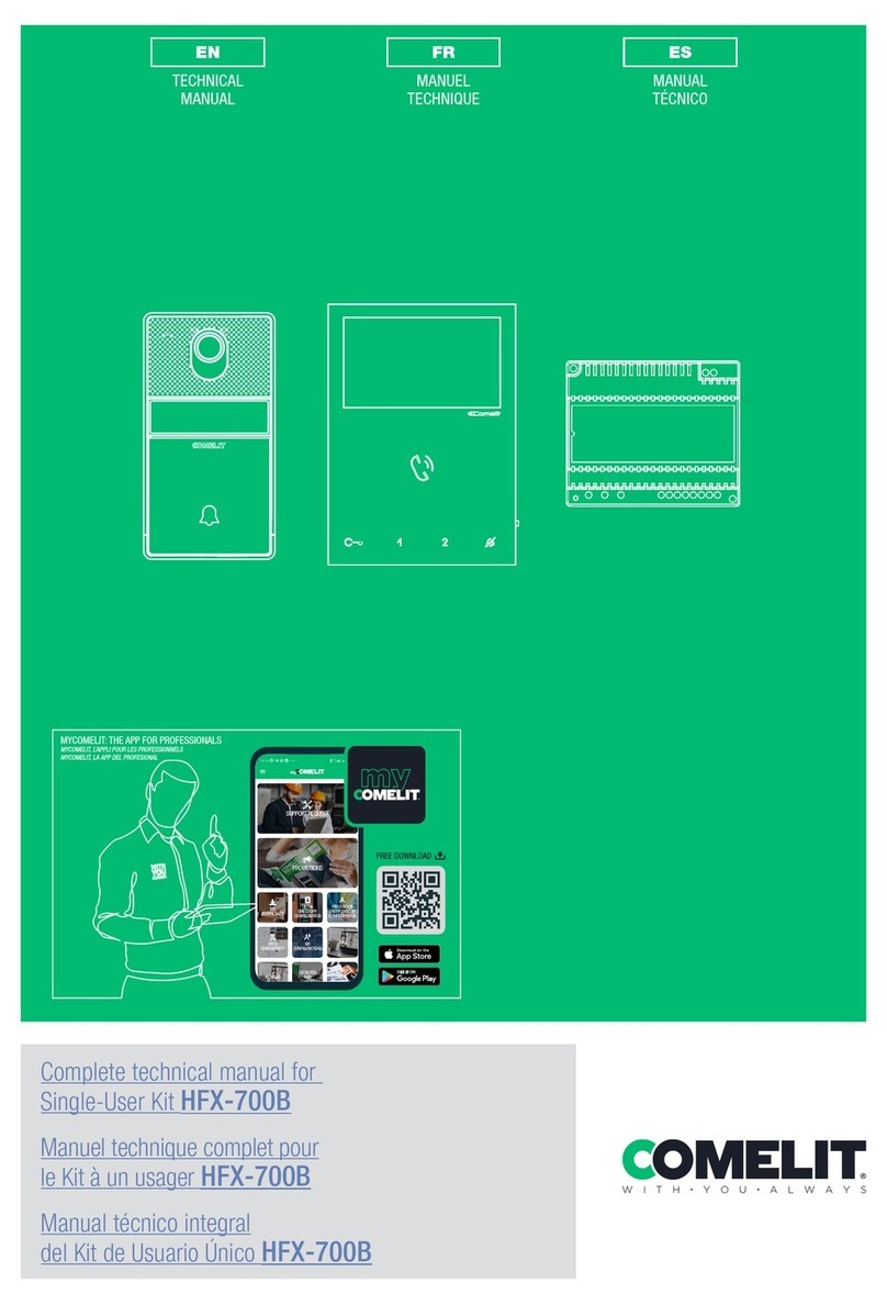
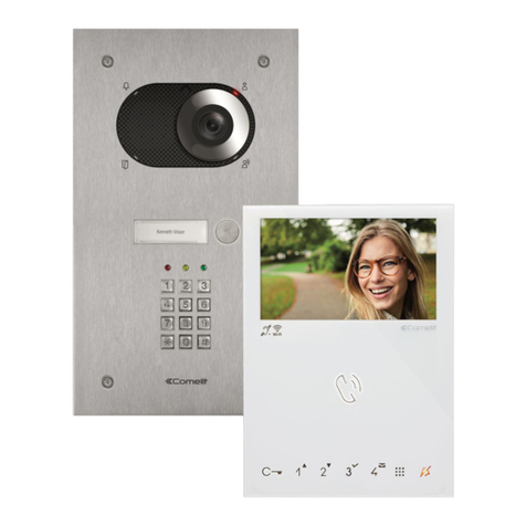
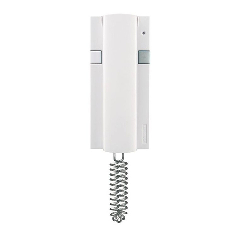
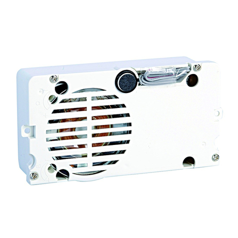
  9. Comelit Simplebus FT/SB/06 User manual

Comelit Simplebus FT/SB/06 User manual

1
FT/SB/06
I Monitor e accessori serieVideocom per impianti videoci-
tofonici con cablaggio a 2 fili non polarizzati. Modalitàdi
installazione e collegamento.
GB
Videocom series monitor and accessories for Simplebus
video door entry systems with 2 non twisted wires.
Installation and connections.
F Moniteurs et accessoires sérieVideocom pour
installations visiophoniques Simplebus avec câblage à
2 fils non polarisés. Modalités d’installation et connexion.
D SerieVideocom Monitor und Zubehör für
Videotorsprechstellen mit SimplebusVerdrahtung.
Installation und Anschlüsse.
ISeguire scrupolosamente le istruzioni fornite dal costruttore.
Tutti gli apparecchi costituenti l'impianto devono essere destinati
esclusivamente all'uso per cui sono stati concepiti.
Effettuare l'installazione in conformitàalle norme vigenti.
Tutti i prodotti sono conformi alle prescrizioni delle direttive CEE
73/23-89/336 ed èattestato dalla presenza della marcatura CE
sugli stessi.
GB
Carefully read and follow the instructions given by the manufacturer.
All the equipment making up the installation must only be used for
the purpose it was built for.
Install the equipment in compliance with the legislation in force.
All products comply with the requirements of the directives EEC
73/23-89/336. This is proved by the CE label displayed on the
products.
F
Suivre scrupuleusement les instructions fournies par le constructeur.
Tous les appareils qui costituent l'installation doivent être destinés
exclusivement àl'utilisation pour laquelle ils ont étéconçus.
Effectuer l'installation conformément aux normes en vigueur.
Tous les produits sont conformes aux prescriptions demandées
par les normes CEE 73/23-89/336. Cela est attestépar la présen-
ce du marque CE sur les produits.
DDie vom Hersteller gelieferten Anweisungen sorgfältig durchle-
sen und befolgen.
Sämtliche die Anlage betreffenden Geräte dürfen ausschliesslich
für den Zweck verwendet werden, für welchen sie geschaffen
worden sind.
Die Installation muss unter Einhaltung der gültigen Richtlinien
ausgeführt werden.
Alle Produkte entsprechen den Richtlinien EG-73/23 und EG-
89/336. Die Übereinstimmung der Produkte mit den genannten
Richtlinien wird beglaubigt durch das Vorhandensein der CE-
Markierung auf den Produkten.
GROUP S.P.A.
Avvertenze
Warnings
Instructions
Anweisungen
1
23
1
1
2
3
8
7
6
5
4
Descrizione monitor
Description of monitor
Description du moniteur
Monitorbeschreibung
I
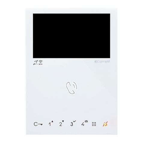
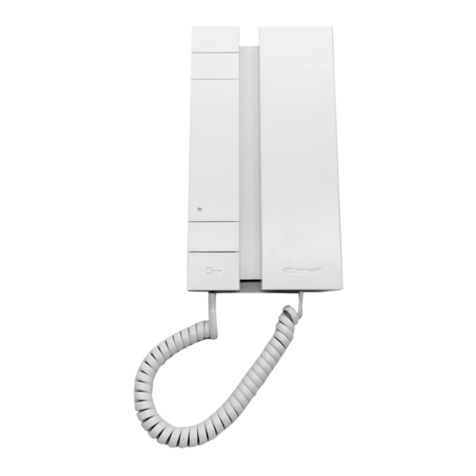
Il monitor videocitofonico serie
Videocom ( art 4701W) ècompatibile
con i monitor delle serie precedenti:
Eurocom, Next, Cristal (ultima versio-
ne), per ogni sistema di cablaggio.
La staffa di fissaggio (art 4714W)com-
pleta il monitor e determina il sistema
di cablaggio.
Valgono gli stessi schemi di collega-
mento descritti sul Foglio tecnico
FT/SB/01 a corredo dei posti esterni
negli impianti Simplebus.
La funzione Privacy, attivabile tramite
l’apposito interruttore ( campana), è
di serie sul monitor Videocom per tutti i
sistemi di cablaggio;essa impedisce la
ricezione della chiamata e l’accensione
del monitor dell’utente che l’ha inserita.
L’attivazione della funzione èsegnalata
dall’accensione del Led Privacy (o).
La staffa (art 4714W) consente di sce-
gliere se usufruire della funzione
Privacy o della funzione Dottore (vedi
varianti E e F).La funzione Dottore,
attivabile sempre tramite l’interruttore
( campana) impedisce la ricezione
della chiamata, l’accensione del moni-
tor ed in automatico comanda l’apertu-
ra della porta chiamante.
1.Ganci di fissaggio alla staffa
2.Regolazione luminosità
3.Regolazione volume
chiamata
4.Pulsante apriporta ( )
5.Pulsante chiamata
centralino/libero (1)
6.Pulsanti (NO) liberi (2) (3)
7.Interruttore Privacy ( )
8.Led Privacy (O)
GB
The Videocom monitor ( art 4701W) is
compatible with all previous series of
monitors : Eurocom, Next, Crystal ( the
latest version) for all types of cabling
systems.
The bracket (art 4714W) completes
the monitor and defines the cabling
system .
For the connection diagrams, you can
refer to the current technical sheet
FT/SB/01 that is provided with the
entrance panels for the Simplebus
systems.
For all the systems theVideocom moni-
tor comes complete as standard with a
switch (with the symbol of a bell )
for the Privacy function .Once inserted,
the switch disables the monitor from
receiving calls and switching on.A LED
(o) will light on to indicate when the
Privacy function is inserted, only when
power supplied.
With bracket (4714W) it is possible to
select either the Privacy function or the
Doctor option ( see following variants
E and F) by means of the same swit-
ch.
When in doctor-on mode , the monitor
will not receive any call nor switch on
but the door lock will automatically be
released upon pressing the call button
at the entrance.
1.Hooks for fixing on the bracket
2.Brightness adjustment
3.Call volume adjustment
4.Door opening push
button ( )
5.Push button for calling
cps/ free (1)
6.(NO) Free push buttons
(2) (3)
7.Privacy switch ( )
8.Privacy LED (O)
F
Le moniteur Videocom ( art 4701W) est
compatible avec les moniteurs des
séries précédentes : Eurocom, Next,
Crystal (la dernière version) pour tout
type de câblage.
La bride (art 4714W) complète le
moniteur et détermine le système de
câblage.
Pour les schémas de connexion, réfé-
rez-vous àla Feuille Technique
FT/SB/01 fournie avec les postes exté-
rieurs des installations Simplebus.
La fonction Privacy, àactiver par l’in-
terrupteur approprié(symbole cloche
) , est de série sur le moniteur
Videocom pour tous les systèmes de
câblage. Celle-ci empêche la réception
de l’appel et l’allumage du moniteur de
l’usager qui l’a activée. L’activation de
la fonction est signalée par l’allumage
de la LED Privacy (symbole o).
La bride (art. 4714W) permet de
choisir si utiliser la fonction Privacy ou
la fonction Docteur (voir variante E et
F) La fonction Docteur, àactiver
toujours par l’interrupteur (symbole clo-
che ) empêche la réception de l’ap-
pel, l’allumage du moniteur et com-
mande automatiquement l’ouverture de
la porte appelante.
1.Crochet de fixation àla bride
2.Réglage luminosité
3.Réglage volume d’appel
4.Bouton ouvre-porte ( )
5.Bouton appel
standard/libre (1)
6.(NO) Boutons libres
(2)-( 3)
7.Interrupteur Privacy ( )
8.LED Privacy (O)
D
Der Videocom Monitor (Art. 4701W) ist
kompatibel zu allenVorgängermodellen
der Serien: Eurocom, Next, Crystal (let-
zte Version) und geeignet für alle
Verdrahtungsarten. Die
Anschlussklemmplatte (Art.4714W)
vervollständigt den Monitor und
definiert das Verdrahtungssystem. Die
Anschlussdiagramme für die vollständi-
ge Installation sind im aktuellen tech-
nischen Manual (FT/SB/01) enthalten.
Der Videocom Monitor bietet für alle
Systeme standardmäßig einen
Schalter (Glockensymbol ) zur
Rufabschaltung (Privacy). Dieser
Schalter deaktiviert den Ruf von der
Torstelle und verhindert die
Einschaltung des Monitors.Eine LED
(Symbol 0) signalisiert die Aktivierung
dieser Funktion, wenn die Anlage
betriebsbereit ist. Die
Anschlussklemmplatte (Art.4714W)
bietet entweder die Möglichkeit der
Rufabschaltung oder die
Doktorschaltung (siehe Variante E und
F). Doktorschaltung: Bei Verwendung
des gleichen Schalters für die
Rufabschaltung wird die Einschaltung
des Monitors und der Rufton unterbun-
den, aber bei Drücken der Ruftaste am
Tortableau wird automatisch der
Türöffner betätigt.
1.Öffnungen zum Fixieren der
Anschlussklemmplatte
2.Helligkeitsregler
3.Ruftonlautstärkeregler
4.Türöffnertaste ( )
5.Taste für Ruf der
Zentrale/frei (1)
6.(NO) frei belegbare Tasten
(2) (3)
7.Rufabschaltung ( )
8.Rufabschaltung LED (0)
1
2
1
23
1
24
147
cm
2
Installazione monitor da parete
Installation of surface monitor
installation moniteur en saillie
Montage des AP-Monitors
2
1
3
1
2
Installazione base da tavolo art. 4712W
Installation of desk base art. 4712W
Installation de la base de table art. 4712W
Montage derTischunterlage art. 4712W
2
1
1
23
3
Come togliere il monitor
How to remove the monitor
Comment enlever le moniteur
Wie der Monitor demontiert wird
•Chiamata fuoriporta
•Floor outdoor call
•Appel palier
•Etagen-ruf
•Chiamata fuoriporta
•Floor outdoor call
•Appel palier
•Etagen-ruf
•Chiamata fuoriporta
•Floor outdoor call
•Appel palier
•Etagen-ruf
Sistema Simplebus. Collegamento del monitor per impianto 1 porta video tradizionale.
Connection of a monitor to a Simplebus system with an analogical video entrance panel.
Système Simplebus. Connexion du moniteur pour installation à1 entrée vidéo traditionnelle.
SimplebusVerdrahtung für Videoinstallationen mit analoger Video -Torsprechstelle
SBV/01V
VARIANTE A -VARIANT A -VARIANTE A -VARIANTE A
C3
P3
C2
P2
AI
C1
P1
CFP
CFP
L
L
CV1
CV2
• Impiego per usi vari del
pulsante P1 (normalmente
dedicato alla chiamata
centralino) della staffa 4714W.
•Application for various uses of
the P1 button (normally
dedicated to the switchboard
call) of bracket 4714W.
•Emploi pour usages différents
du bouton P1 (normalement
dédiéàl’appel du standard)
de la bride 4714W.
•Anwendung für Verschiedenen
Benutzungen von P1 Taste
(normaleweise für den Ruf der
Zentrale Bestimmt) des bugels
4714W.
VARIANTE B -VARIANT B -VARIANTE B -VARIANTE B
VARIANTE D -VARIANT D -VARIANTE D -VARIANTE D
C3
P3
C2
P2
AI
C1
P1
CFP
CFP
L
L
CV1
CV2
C3
P3
C2
P2
C1
P1
CFP
CFP
L
L
CV1
CV2
AI
•Attivazione opzionale
accensione interna sul pulsante
P1 della staffa 4714W (solo per
impianti senza centralino di
portineria con 1 o 2 ingressi).
•Optional activation of
self-ignition on the P1 push
button of bracket 4714W (only
for systems without CPS and
with 1 or 2 entrance units).
•Activation en option
auto-allumage sur bouton P1 de
la bride 4714W (seulement pour
installations sans standard de
conciergerie et avec
1 ou 2 entrées).
•Optionale Aktivierung interne
Einschaltung auf Taste P1 des
Bügels
4714W ( nur für Anlagen ohne
Zentrale mit 1 oder 2
Eingängen).
•Attivazione opzionale
accensione interna sul
pulsante P3 della staffa
4714W.
•Optional activation of
self-ignition on the P3 push
button of bracket 4714W.
•Activation en option
auto-allumage sur
bouton P3 de la bride 4714W.
•Optionale Aktivierung interne
Einschaltung auf Taste P3 des
Bügels
4714W.
VARIANTE C -VARIANT C -VARIANTE C -VARIANTE C
C3
P3
C2
P2
AI
C1
P1
CFP
CFP
L
L
CV1
CV2
•Attivazione opzionale
accensione interna sul
pulsante P2 della staffa
4714W (solo per impianti con
1 o 2 ingressi e centralino di
portineria 1998).
•Optional activation of
self-ignition on the P2 push
button of bracket 4714W (only
for systems with 1 or 2
entrance units and CPS 1998).
•Activation en option
auto-allumage sur
bouton P2 de la bride 4714W
(seulement pour installations
avec 1 ou 2 entrées et
standard de conciergerie
1998).
•Optionale Aktivierung interne
Einschaltung auf Taste P2 des
Bügels
4714W ( nur für Anlagen
mit 1 oder 2 Eingängen
und Zentrale 1998).
5
VARIANTE E -VARIANT E -VARIANTE E -VARIANTE E
Abilitazione della funzione Privacy
•Spostare il jumper JP1 come in figura per
abilitare la funzione Privacy.
Enabling of Privacy option
•Move jumper JP1 as shown in the picture
to enable the Privacy function.
Activation de la fonction Privacy
•Déplacer le petit pont JP1 comme montré
dans la figure pour activer la fonction Privacy.
Aktivierung der Rufabschaltung
(Privacy).
•Jumper JP1 in Position wie abgebildet
aktiviert die Rufabschaltungsfunktion.
C3
P3
C2
P2
AI
C1
Jumper JP1
VARIANTE F -VARIANT F -VARIANTE F -VARIANTE F
Abilitazione della funzione Dottore
•Spostare il jumper JP1 come in figura per
abilitare la funzione Dottore.
Enabling of Doctor option
•Move jumper JP1 as shown in the picture
to enable the Doctor option.
Activation de la fonction Docteur
•Déplacer le petit pont JP1 comme montré
dans la figure pour activer la fonction
Docteur.
Aktivierung der Doktorschaltung
•Jumper JP1 in Position wie abgebildet
aktiviert die Doktorschaltungsfunktion.
C3
P3
C2
P2
AI
C1
Jumper JP1
Variante schemi elettrici
Variants of connection diagrams
Variantes des schémas de connexion
Anschlussvarianten
4
•Chiamata fuoriporta
•Floor outdoor call
•Appel palier
•Etagen-ruf
•Chiamata fuoriporta
•Floor outdoor call
•Appel palier
•Etagen-ruf
•Chiamata fuoriporta
•Floor outdoor call
•Appel palier
•Etagen-ruf
Sistema Simplebus. Collegamento del monitor per impianto 1 porta video tradizionale con alimentatore 1536.
Connection of a monitor to a Simplebus system with an analogical video entrance panel and power supply art. 1536.
Système Simplebus. Connexion du moniteur pour installation à1 entrée vidéo traditionnelle avec alimentation 1536.
SimplebusVerdrahtung für Videoinstallationen mit analoger Video -Torsprechstelle und zentralem Netzgerät Art. 1536
SBV/02V
Collegamento monitor con segnale video in cascata
Connection of monitor with video signal in cascade
Connexion du moniteur avec signal vidéo en cascade
MonitoranschlußmitVideosignal in Kaskade
SB/VA
•Chiamata fuoriporta
•Floor outdoor call •Appel palier
•Etagen-ruf
•Chiamata fuoriporta
•Floor outdoor call •Appel palier
•Etagen-ruf
CERTIFICAZIONE DEI SISTEMI
QUALITA' DELLE AZIENDE
UNI EN - ISO 9001
24020 Rovetta - S. Lorenzo (Bergamo) Italy Tel. 0346 72180 - fax 0346 71436
internet: http://www.comelit.it •e-mail: [email protected]
GROUP S.P.A.
FT/SB/06 - 1aedizione 04/2001 - cod. 22590207

Other Comelit Intercom System manuals

Comelit Quadra Series User manual

Comelit

Comelit Quadra Series User manual

Comelit 8472S User manual

Comelit

Comelit 8472S User manual

Comelit FT KIT 05 User manual

Comelit

Comelit FT KIT 05 User manual

Comelit Ciao User manual

Comelit

Comelit Ciao User manual

Comelit Mini 6751W User manual

Comelit

Comelit Mini 6751W User manual

Comelit 316 Sense User manual

Comelit

Comelit 316 Sense User manual

Comelit Maxi 6813W User manual

Comelit

Comelit Maxi 6813W User manual

Comelit Easycom ViP internal unit User manual

Comelit

Comelit Easycom ViP internal unit User manual

Comelit iPower kit User manual

Comelit

Comelit iPower kit User manual

Comelit Simplebus2 Ultra UT2010 User manual

Comelit

Comelit Simplebus2 Ultra UT2010 User manual

Comelit Mini 6750W User manual

Comelit

Comelit Mini 6750W User manual

Comelit Icom 4680 User manual

Comelit

Comelit Icom 4680 User manual

Comelit FT/SB/07 User manual

Comelit

Comelit FT/SB/07 User manual

Comelit KCA2061A User manual

Comelit

Comelit KCA2061A User manual

Comelit KAE5064 User manual

Comelit

Comelit KAE5064 User manual

Comelit 8171I User manual

Comelit

Comelit 8171I User manual

Comelit FT CB 07 Instruction Manual

Comelit

Comelit FT CB 07 Instruction Manual

Comelit Icona Manager User manual

Comelit

Comelit Icona Manager User manual

Comelit 4879KC User manual

Comelit

Comelit 4879KC User manual

Comelit Bravo Color User manual

Comelit

Comelit Bravo Color User manual

Comelit COMTEL MT VCT 05 User manual

Comelit

Comelit COMTEL MT VCT 05 User manual

Comelit 4894E User manual

Comelit

Comelit 4894E User manual

Comelit VIP System User guide

Comelit

Comelit VIP System User guide

Comelit Planux Lux User manual

Comelit

Comelit Planux Lux User manual

Popular Intercom System manuals by other brands

Busch-Welcome 83121 manual

Busch-Welcome

Busch-Welcome 83121 manual

FONESTAR KE-404 instruction manual

FONESTAR

FONESTAR KE-404 instruction manual

Doss DHF42PC Installation and operation manual

Doss

Doss DHF42PC Installation and operation manual

Wind Crest SERIAL BUS quick start guide

Wind Crest

Wind Crest SERIAL BUS quick start guide

Fermax DETECTA-6 user manual

Fermax

Fermax DETECTA-6 user manual

Directed 2102 owner's guide

Directed

Directed 2102 owner's guide

Entrotec PRO-DPA Installation and setup guide

Entrotec

Entrotec PRO-DPA Installation and setup guide

Elvox 0930/000.04 instruction sheet

Elvox

Elvox 0930/000.04 instruction sheet

FARFISA INTERCOMS Project Series Technical manual

FARFISA INTERCOMS

FARFISA INTERCOMS Project Series Technical manual

ASL INTERCOM BS 17 user manual

ASL INTERCOM

ASL INTERCOM BS 17 user manual

Aiphone TD-H Series Installation & operation manual

Aiphone

Aiphone TD-H Series Installation & operation manual

Robin SlimLine user manual

Robin

Robin SlimLine user manual

CDVI DMR18S Technical manual

CDVI

CDVI DMR18S Technical manual

Extel EASY BUS 3 Installation and user guide

Extel

Extel EASY BUS 3 Installation and user guide

Velleman CAMSET3 instruction manual

Velleman

Velleman CAMSET3 instruction manual

Commax CDV-40NM user manual

Commax

Commax CDV-40NM user manual

Fermax MEET Concierge Installer manual

Fermax

Fermax MEET Concierge Installer manual

Axema VAKA A66 SOLO manual

Axema

Axema VAKA A66 SOLO manual

manuals.online logo
manuals.online logoBrands
  • About & Mission
  • Contact us
  • Privacy Policy
  • Terms and Conditions

Copyright 2025 Manuals.Online. All Rights Reserved.