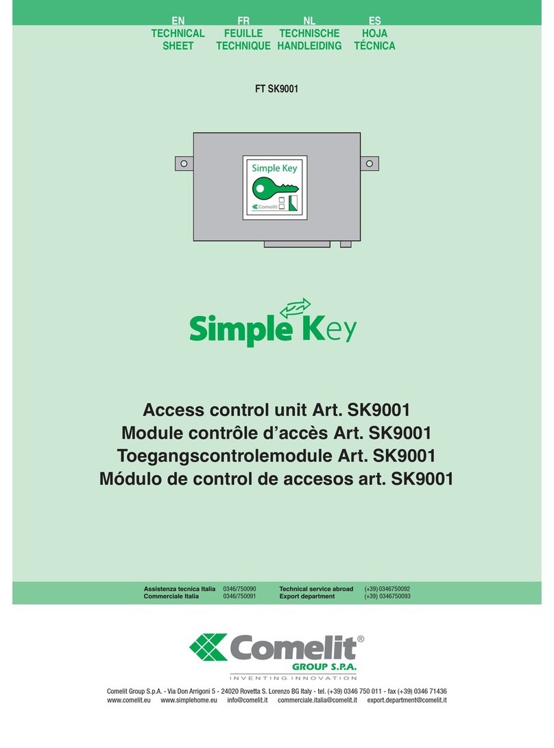
Comelit Simple Key SK9000I User manual

Assistenza tecnica Italia 0346/750090
Commerciale Italia 0346/750091
Technical service abroad (+39) 0346750092
Export department (+39) 0346750093
Comelit Group S.p.A. - Via Don Arrigoni 5 - 24020 Rovetta S. Lorenzo BG Italy - tel. (+39) 0346 750 011 - fax (+39) 0346 71436
IT
MANUALE
TECNICO
EN
TECHNICAL
MANUAL
FR
MANUEL
TECHNIQUE
NL
TECHNISCHE
HANDLEIDING
ES
MANUAL
TÉCNICO
Unità di controllo accessi Art. SK9000I
Access control unit Art. SK9000I
Module contrôle d'accès Art. SK9000I
Toegangscontrolemodule Art. SK9000I
Módulo de control de accesos art. SK9000I

IT
EN
FR
NL
ES
2
Avvertenze
• Effettuarel’installazioneseguendoscrupolosamenteleistruzionifornitedalcostruttoreedinconformitàallenormevigenti.
• Tuttigliapparecchidevonoesseredestinatiesclusivamenteall’usopercuisonostaticoncepiti.Comelit Group S.p.A.declinaogniresponsabilitàperunutilizzoimpropriodegli
apparecchi,permodicheeffettuatedaaltriaqualunquetitoloescopo,perl’usodiaccessoriematerialinonoriginali.
• Tuttiiprodottisonoconformialleprescrizionidelledirettive2006/95/CE(chesostituisceladirettiva73/23/CEEesuccessiviemendamenti)eciòèattestatodallapresenzadella
marcaturaCEsuglistessi.
• Evitarediporreilidimontanteinprossimitàdicavidialimentazione(230/400V).
• Gliinterventidiinstallazione,montaggioeassistenzaagliapparecchielettricidevonoessereeseguitiesclusivamentedaelettricistispecializzati.
• Nell'impiantoelettricodell'edicio deveessere previstouninterruttore direteonnipolare conun'aperturadi contattodi almeno3mmin gradodisezionare l'alimentazionedel
dispositivo.
• Toglierel’alimentazioneprimadieffettuarequalsiasimanutenzione.
• Rimettereleprotezionisuimorsettiechiuderelosportellinodiispezionedopoogniintervento.
• IldispositivoèconformeallanormaEN60950-1relativaallasicurezzadiapparecchiatureperlatecnologiadell'informazione.
Warning
• Installtheequipmentbycarefullyfollowingtheinstructionsgivenbythemanufacturerandincompliancewiththestandardsinforce.
• Alltheequipmentmustonlybeusedforthepurposeitwasdesignedfor.Comelit Group S.p.A.declinesanyresponsibilityforimproperuseoftheapparatus,formodicationsmade
bythirdpartiesforanyreasonorpurpose,andfortheuseofnon-originalaccessoriesandmaterials.
• Alltheproductscomplywiththerequirementsofthe2006/95/CEdirectives(whichreplacedirective73/23/CEEandsubsequentamendments),ascertiedbytheCEmarkonthe
products.
• Donotrouteriserwiresinproximitytopowersupplycables(230/400V).
• Installation,mountingandassistanceproceduresforelectricaldevicesmustonlybeperformedbyspecialisedelectricians.
• Theelectricalsystemofthebuildingmustbettedwithanomnipolarmainsswitchwithacontactopeningofatleast3mm,whichiscapableofisolatingthepowersupplyofthedevice.
• Cutoffthepowersupplybeforecarryingoutanymaintenancework.
• Placetheprotectionbackovertheterminalsandclosetheinspectiondooraftereveryprocedure.
• ThedeviceconformstostandardEN60950-1relatingtothesafetyofinformationtechnologyequipment.
Avertissements
• Effectuerl’installationensuivantscrupuleusementlesinstructionsfourniesparleconstructeuretconformémentauxnormesenvigueur.
• Touslesappareilsdoiventêtrestrictementdestinésàl’emploipourlequelilsontétéconçus.La société Comelit Group S.p.A.déclinetouteresponsabilitéencasdemauvaisusage
desappareils,pourdesmodicationseffectuéespard’autrespersonnespourn’importequelleraisonetpourl’utilisationd’accessoiresetmatériauxnond’origine.
• Touslesproduitssontconformesauxprescriptionsdeladirective2006/95/CE(quiremplaceladirective73/23/CEEetamendementssuccessifs).Celaestattestéparlaprésence
dumarquageCE surlesproduits.
• Éviterdeplacerleslsdemontantàproximitédescâblesd’alimentation(230/400V).
• Lesinterventionsd’installation,demontageetd’assistanceauxappareilsélectriquesdoiventêtreeffectuéesexclusivementpardesélectriciensspécialisés.
• L’installationélectriquedubâtimentdoitêtremunied’uninterrupteurderéseauomnipolaireavecuneouverturedecontactd’aumoins3mmenmesuredesectionnerl’alimentation
dudispositif.
• Couperl’alimentationavantd’effectuertouteopérationd’entretien.
• Remettrelesprotectionssurlesbornesetfermerlaported’inspectionaprèschaqueintervention.
• LedispositifestconformeàlanormeEN60950-1relativeàlasécuritédeséquipementspourlatechnologiedel’information.
Waarschuwingen
• Voerdeinstallatiewerkzaamhedenzorgvuldiguitvolgensdedoordefabrikantgegeveninstructiesenmetinachtnemingvandegeldendenormen.
• Allecomponentenmogenalleengebruiktwordenvoordedoeleindenwaarvoorzezijnontworpen.Comelit Group S.p.A.isnietverantwoordelijkvooroneigenlijkgebruikvande
apparatuur,voorwijzigingendieomwelkeredendanookdoorderdenzijnaangebracht,envoorhetgebruikvanaccessoiresenmaterialendienietdoordefabrikantzijnaangeleverd.
• Alleproductenvoldoenaandeeisenvanderichtlijn2006/95/EG(diederichtlijn73/23/EEGenlaterewijzigingenvervangt).DitwordtbevestigddoorhetCE-labelopdeproducten.
• Monteerdeadersvandestamleidingnietindenabijheidvanvoedingskabels(230/400V).
• Deinstallatie-,montage-enservicewerkzaamhedenaandeelektrischeapparatenmogenuitsluitenddoorgespecialiseerdeelektricienswordenverricht.
• Deelektrischeinstallatievanhetgebouwmoetvoorzienzijnvaneenalpoligenetschakelaarmeteencontactafstandvantenminste3mmdiehetapparaatvandenetvoedingkan
scheiden.
• Sluitdestroomtoevoeraf,voordatuonderhoudswerkzaamhedenuitvoert.
• Plaatsdebeschermingenweeropdeklemmenensluithetinspectieluiknadewerkzaamheden.
• HetapparaatvoldoetaandenormEN60950-1betreffendedeveiligheidvanapparatuurvoorinformatietechniek.
Advertencias
• Lainstalaciónsehadeefectuarenconformidadconlasnormasvigentes,siguiendoatentamentelasinstruccionessuministradasporelfabricante.
• Todoslosaparatosdebendestinarseexclusivamentealusoparaelcualhansidoconstruidos.Comelit Group S.p.A. declinatodaresponsabilidadporelusoimpropiodelos
aparatos,porcambiosefectuadosportercerosporcualquiermotivoonalidadyporelusodeaccesoriosymaterialesnooriginales.
• TodoslosproductossonconformesalosrequisitosdelasDirectivas2006/95/CE(quesustituyelaDirectiva73/23/CEEysucesivasenmiendas)comodemuestralapresenciadela
marcaCEenellos.
• Noponerloscablesdelacolumnamontantecercadeloscablesdealimentación(230/400V).
• Lainstalación,elmontajeyelmantenimientodelosaparatoseléctricosdebenserefectuadosexclusivamenteporelectricistasespecializados.
• Enlainstalacióneléctricadelediciotienequehaberuninterruptordecorteomnipolarconunadistanciadeaperturadeloscontactosdealmenos3mm,capazdecortarla
alimentacióndeldispositivo.
• Antesdeefectuarcualquieroperacióndemantenimientohayquecortarlaalimentación.
• Trasefectuarlaintervención,hayqueponerlaproteccióndelosbornesycerrarlatapadeinspección.
• EldispositivoesconformeconlanormaEN60950-1sobreseguridaddeaparatoselectrónicosempleadosenelsectordelainformaciónycomunicación.

IT
3
Introduzione
L’articoloSK9000èun’unitàdicontrollostand-alone(autonoma)con
lettore integrato che viene usata per gestire le chiavi elettroniche
SK9050eSK9052.E’utilizzatapercontrollarel’accessodiunvarco
dotatodiserraturaelettricaodiautomatismo.
E’ fornito pronto per l’uso. Viene inizializzato passando un badge
davanti all’unità alimentata per la prima volta. Tale badge diventa
quindilachiavemaster,chesipotràusareperaggiungerealtribadge.
Struttura dell'unità
Laschedaèfornitadi:
-1deviatoreperaccedereallaprogrammazione
-3pulsantichevengonousatipercambiareiparametri
-3LEDchemostranoglistatidell’unità
-lemorsettiere
-1connettore(J5)perl’aggiornamentofirmware
Descrizione dei morsetti
AL:Alimentazione12-33Vcco12-24Vca
J1:BusdicomunicazioneSK9093
J2:contattoreléNC/NO
J3:pulsanteaperturalocale
J4:lettoreintegrato
Modalità di programmazione
IldeviatoreS3èutilizzatoperentrareinprogrammazione:
S3 in posizione “0” ⇒modalitàoperativa
S3 in posizione “ON” ⇒modalità di programmazione
Nota:InmodalitàdiprogrammazioneilLEDL2eilLEDdellettore
lampeggianorapidamente.
Pergestiregliaccessil’unitàdeveessereinmodalitàoperativa.
Modifica del tempo di apertura
-SpostareildeviatoreS3 su“ON” (programmazione)
- Premere S1 ripetutamente per impostare il tempo di apertura
(un secondo per ogni pressione). Successivamente, rimettere
S3 in modalità operativa. Un doppio bip confermerà la riuscita
dell’operazione.
Iltempominimoimpostabileè1secondo.
Iltempomassimoimpostabileè99secondi.
Il tempo di apertura è impostato di fabbrica a 5 secondi.
Gestione delle chiavi utente
1. Chiave master
Il primo badge accostato all’unità diventa la chiave master. Il LED
verde lampeggerà tre volte per indicare la creazione della chiave
master,laqualepermetteràdientrareinmodalitàdiprogrammazione
senzadoveraprirel’unità.
2. Aggiungere una chiave utente
L’unitàdeveessereinmodalitàoperativa(deviatoreS3inposizione
“0”).
Passare la chiave master davanti al lettore. Il LED lampeggerà
rapidamente verde/rosso per segnalare l’ingresso in modalità di
programmazione. Per aggiungerechiavi utente,passarle davantial
lettorealnediregistrarle.
Per uscire dalla modalità di programmazione, ripassare la chiave
masteroaspettare15secondisenzafareoperazioni(ilLEDsmetterà
dilampeggiare).
3. Reset parziale – reset della chiave master
Incaso dismarrimentodella chiavemaster,èpossibile cancellarla
dallamemoriadell’unitàeprogrammareunaltrobadgecomechiave
master,comesegue:
-SpostareildeviatoreS3su“ON” (programmazione)
-PremereS2per5secondi,nchésiaccenderàilLEDL3
-RilasciareS2
-Tornare al modo operativo. Un doppio bip confermerà la riuscita
dell’operazione.
Da questo momento, il primo badge passato davanti al lettore
diventeràlanuovachiavemaster.
4. Reset totale
-SpostareildeviatoreS3su“ON” (programmazione)
- Premere S2 per 10 secondi. Dopo 5 secondi si accenderà L3
(resetparziale).TenerepremutoS2altri5secondinchéilLEDL2
lampeggeràvelocemente(resettotale).
-RilasciareS2
-Tornare al modo operativo. Un doppio bip confermerà la riuscita
dell’operazione.
Ilresettotaleabilital’unitàallaprimainizializzazione:
-lapassworddiaccessoall’unitàè“0000”
-lachiavemasterelechiaviutentesonocancellate.
5. Cancellazione di una chiave utilizzando il kit SK9093
Con il software del kit SK9093, fornito separatamente, è possibile
visualizzare l’elenco dei badge programmati nell’unità e cancellarli.
Per fare questo si deve collegare l’unità al PC utilizzando il cavo
fornitonelkitelanciareilprogramma.
-Cliccare su“Gestionechiavi”e poi su“Genera elencochiavi” per
visualizzarle
- Si può quindi cancellare una o più chiavi selezionandole e poi
cliccando su “Cancellare le chiavi selezionate”. Oppure si può
cancellarel’interamemoriacliccandosu“Cancellaretuttelechiavi”.
L’unitàsaràquindicompletamentevuota,eilprimobadgeaccostato
allettorediventeràlanuovachiavemaster.
Funzionamento normale dell'unità
Quando l'unità è in modalità operativa normale, all'interno il LED
rossoL1èssoeilLEDrossoL2lampeggialentamente.All'esterno,
illettoreèrossossoesispegnebrevementeogni3secondi.
Se l’unità non funziona correttamente, questi LED danno segnali
differenti.Inquestocasotogliereeridarealimentazione.Sequesto
nonèsufciente,contattarel’assistenzatecnicaComelit.
Caratteristiche tecniche
•Tempodiaperturaregolabileda1a99secondi.
•UscitaacontattopulitoMAX5Aa250Vac
•Assorbimento:70mAariposo,160mAconreléattivo
•Temperaturadifunzionamento:-30°/+55°C
•Tensionedifunzionamento:12-33Vcco12-24Vca
•Dimensioni:62x88x23mm(AxLxP)

EN
4
General introduction
TheSK9000unitisastand-alonecontrolunitwithanintegralreader
whichisusedtomanagetheelectronickeysSK9050andSK9052.It
isusedtocontrolaccesstoadoorfittedwithanelectroniclockoran
automaticdevice.
Itissuppliedreadyforuse.Itisinitialisedbyswipingthefirsttoken
overtheunusedunitwhichthenbecomesthemasterfobtowhichyou
canthenaddothertokens.
Layout of the unit
Thecardismadeupof:
-aswitchusedtoaccesstheprogramming
-threepushbuttonsthatareusedtoaffecttheparameters
-thethreeLED’sthatshowthestatusesoftheunit
-connectionterminals
-aJ5firmwareupdateconnector
Description of terminals
AL:Powersupply12-33Vdcor12-24Vac
J1:communicationbusSK9093
J2:NO/NCrelayoutput
J3:exitpushbutton
J4:integralreader
Programming modes
TheS3switchisusedtoswitchbetweenprogrammingmodes.
S3 in “0” position ⇒Operatingmode
S3 in “ON” position ⇒Programming mode
Note:InprogrammingmodetheL2LEDandthereaderLEDflash
rapidly.
Youmustgobacktooperatingmodefortheunittomanageaccess.
Setting the opening timer
-TurnswitchS3to“ON” (Programming)
-Pressbutton S1 severaltimestoadjustthetimeunits(onepress
persecond).OnceS3hasswitchedbacktooperatingmodeadouble
confirmationbeepwillvalidatethisforyou.
Theminimumtimingsettingis1second.
Themaximumtimingsettingis99seconds.
The unit is supplied with a 5 second opening time set by the
factory.
User’s token management
1. Master fob.
Thefirst token swiped inthe unit willbecome the masterfob. The
green LED will flash three times to indicate master fob creation. It
willenableyoutoenterprogrammingmodewithouthavingtoaccess
theunit.
2. Adding a user token
TheunitmustbeinOPERATINGmode(switchS3inposition“0”).
Passthetokeninfrontofthereader.TheLEDwillflashquickly(green/
red)andyouareinprogrammingmode.Toaddusertokensyoujust
havetopasstheminfrontofthereadertoregisterthem.
To exit programming mode, pass the master fob again or wait 15
secondswithoutdoinganything.(Theflashingwillstop)
3. Partial reset - reset of Master Fob
IncasetheMasterFobislost,itispossibletoonlyresettheMaster
FobinordertoprogramanothertokenasMasterFob
-TurnSwitchS3to“ON” (Programming)
-PressS2for5seconds,tillL3LEDlightson
-ReleaseS2
-SwitchbacktoOperatingMode(adoublebeeptellsyouthattheunit
hasbeenpartiallyreset)
Inthismoment,thefirsttokenyouswipetothereaderWILLBECOME
THENEWMasterFob
4. Complete reset
-TurnswitchS3to“ON” (Programming)
- Press S2 for 10 seconds. After 5 seconds L3 lights on (Partial
Reset). Keep pressed 5 seconds again till L2 LED flashes quicky
(CompleteReset)
-ReleaseS2
-SwitchbacktoOperatingMode(adoublebeeptellsyouthattheunit
hasbeencompletelyreset)
Resettingtozeroenablestheinitialisationprocess:
-thepasswordtoaccesstheunitis“0000”.
-usertokensandthemasterfobaredeleted.
5. Deleting a token using the SK9093 kit
Using the SK9093 software, supplied separately, it is possible to
displaythetokensprogrammedintotheunitanddeletethem.Todo
thisyoujusthavetoconnecttotheunitusingthecablesuppliedwith
thekitandlaunchtheprogram.
- Click on “Token management” then “Scan the list of tokens” to
displaythem.
-Youcantheneitherdeletetheusertokens:checkthetokensthen
clickon“deletetheselectedtoken(s)”ordeletethewholememory:
Clickon“Deletealltokens”,theunitwillthenbecompletelycleared
andthefirsttokenswipedoverthereaderwillbecomeyourmaster
fob.
Normal working of the unit
WhenthemoduleisinnormalOperatingMode,insidetheredLedL1
isfixed,andtheredL2flashesslowly.Outside,thereaderisfixedred,
switchingoffbrieflyevery3seconds.
If the unit is not working properly, these LEDs are giving different
indications.Inthiscaseturn thepowerOFFandthen ONagain.If
thisdoesnotwork,pleasecontactouraftersalesservicedepartment.
Technical characteristics
•Openingtimecanbeadjustedfrombetween1and99seconds.
•Outputviadrycontactmax.5Aat250VAC
•Powerconsumption:70mAwhenidle,160mAwhenrelayactive
•Operatingtemperature:-30°C-+55°C
•Operatingvoltage:12-33Vdcor12-24Vac
•Dimensions(HXLXD):62x88x23mmz

FR
5
Présentation générale
LemoduleSK9000estuneunitédecontrôleautonomeavecantenne
delectureintégréquipermetdegérerlesclésélectroniquesSK9050,
etSK9052.Ilpermetdecontrôlerl’accèsàuneporteéquipéed’une
serrureélectriqueouundispositifautomatique.
Ilestlivréprêtàfonctionner.L’initialisationestréaliséeparprésentation
dupremierbadgesurlacentraleviergequidevientlebadgemaîtreet
permetensuited’ajouterd’autresbadges.
Présentation du module
Lacarteestcomposée:
-d’unswitchpermettantd’accéderàlaprogrammation
-detroispoussoirspermettantd’agirsurlesparamètres
-detroisvoyantsledrougesindiquantlesétatsdelacentrale
-deborniersderaccordement
-d’unconnecteurdemiseàjourdurmwareJ5
Description des bornes
AL:Alimentation12à33Vccou12à24Vca
J1:BusdecommunicationSK9093
J2:SortierelaisNO/NF
J3:poussoirdesortie
J4:antenneintégrée
Modes de programmation
LeswitchS3permetdebasculerenmodedeprogrammation
S3 en position "0" ⇒Modefonctionnement
S3 en position "ON"⇒Mode programmation
Nota :EnmodeprogrammationlevoyantL2ainsiqueceluidelatête
delectureclignotentrapidement.
Pourquela centralepuissegérer lesaccès,il fautimpérativement
revenirenmodefonctionnement
Réglage de la temporisation d’ouverture
-MettreleswitchS3sur"ON" (Programmation)
-Appuyerplusieurs foissurleboutonS1pourrégler lesunitésde
latemporisation(unappuiparseconde).UnefoisS3 rebasculéen
mode fonctionnement, un double bip de confirmation vous informe
delavalidation.
Lavaleurminimumdelatemporisationestde1seconde.
Lavaleurmaximumdelatemporisationestde99secondes.
Le module est livré avec un réglage d'usine de temporisation
d’ouverture de 5 secondes.
Gestion des badges Usager
1. Badge Maître
Lepremierbadgeprésentédevantlemoduleferaofficedebadgede
programmation,ilvousserviraàentrerenmodeprogrammationsans
avoiràaccéderlacentrale.
2. Ajout d'un badge utilisateur
LacentraledoitêtreenModeFONCTIONNEMENT(positon"0"du
switchS3).
PassezlebadgeMaîtredevantl’antennedelecture.Levoyantclignote
rapidement(Vert/Rouge),vousêtesenmodeprogrammation.Pour
ajouterdesbadgesutilisateurs,ilsuffitdelespasserdevantl’antenne
delecturepourlesenregistrer.
Pour sortir du mode de programmation, repasser le badge de
programmation,ouattendez15secondessansaucunemanipulation.
(Leclignotements’arrête)
3. Remise à zéro Partielle – Reset du Badge Maître
Dans le cas où le Badge Maître est perdu, il est possible de faire
seulementlaremiseàzéroduBadgeMaîtreafindeprogrammerun
autrebadgecommeBadgeMaître.
-TournezleSwitchS3sur“ON” (Programmation)
- Appuyez sur S2 pendant 5 secondes, jusqu’à ce que la LED L3
s’allume
-RelâchezS2
-RevenezauModedeFonctionnement(undoublebipvousdiraque
lemoduleaétépartiellementremisàzéro)
Maintenant le premier badge que vous présenterez au lecteur
deviendralenouveauBadgeMaître.
4. Remise à zéro complète
-TournezleSwitchS3sur“ON” (Programmation)
- Appuyez sur S2 pendant 10 secondes. Après 5 secondes L3
s’allume(RemiseàzéroPartielle).Maintenezlapressionpourencore
5 secondes jusqu’à ce que la LED L2 clignotement rapidement
(RemiseàzéroComplète)
-RelâchezS2
-RevenezauModedeFonctionnement(undoublebipvousdiraque
lemoduleaétécomplètementremisàzéro.)
Laremiseàzéropermetl’initialisation:
-motdepassed’accèsàlacentraleà«0000».
-suppressiondesbadgesutilisateursetdubadgemaître.
5. Suppression de badge à l’aide du kit SK9093
Ilestpossible,aveclelogicielSK9093,fourniséparément,devisualiser
lesbadgesprogrammésdanslacentraleetdelessupprimer.Pour
cela,ilsuffitdeseconnecteràlacentraleàl’aideducordonlivréavec
lekitetdelancerleprogramme.
-Cliquezsur«Gestiondesbadges»puis«Lecturedelalistedes
badges»pourlesvoirapparaître
-Vous pouvez soit supprimer les badges utilisateurs : cochez les
badges puis cliquez sur « supprimer le(s) badge(s) sélectionné(s),
soiteffacerlatotalitédelamémoire:Cliquezsur«Supprimertous
lesbadges»,lacentraleseraalorstotalementviergeetlepremier
badge passé devant la tête de lecture deviendra votre badge de
configuration.
Fonctionnement normal du module
Quand le module est en Mode de Fonctionnement normale, à
l’intérieurelaLedL1estrougefixeetL2clignotelentementenrouge.
Al'extérieure,lelecteurestrougefixe,s'éteingnantbrièvementtoutes
les3secondes.
Silemodulene fonctionnepascorrectement,ces LEDsdonneront
des indications différentes. Dans ce cas éteignez l’alimentation et
après allumez-ladenouveau.Sicelanefonctionnepas,veuillezs’il
–vous-plaîtcontacternotreServiceAprès-Ventes.
Caractéristiques techniques
•Réglagedelatemporisationd’ouvertureentre1et99secondes.
•Sortieparcontactsecmaxi5Asous250VAC
•Consommation:70mAaurepos,160mArelaisactif
•Températuredefonctionnement:-30°cà+55°c
•Tensiondefonctionnement:12à33Vccou12à24Vca
•Dimension(hxlxp):62x88x23mm

NL
6
Algemene informatie
De module SK9000 is een onafhankelijke regeleenheid met een
geïntegreerde leesantenne voor het beheren van de elektronische
sleutelsSK9050enSK9052.Demodulecontroleertdetoegangtot
eendeurmeteenelektrischslotofeenautomatischeinrichting.
Hijwordtgebruiksklaargeleverd.Deinitialisatievindtplaatsdoorde
eerste badge voor de lege centrale te houden. Deze badge wordt
daardoor de masterbadge, waaraan vervolgens andere badges
kunnenwordentoegevoegd.
Beschrijving van de module
Dekaartbestaatuit:
-eenswitchvoortoegangtotdeprogrammering
-driedrukknoppenvoorhetinstellenvandeparameters
-drierodeled’sdiedestatusvandecentraleaangeven
-aansluitblokken
-eenconnectorvoorhetupdatenvandefirmwareJ5
Beschrijving van de klemmen
AL:Voeding12-33Vdcof12-24Vac
J1: CommunicatiebusSK9093
J2:UitgangrelaisNO/NG
J3:Drukknopuitgang
J4:Geïntegreerdeantenne
Programmeermodi
Met de switch S3 kan worden overgeschakeld naar de
programmeermode
S3 in positie “0” ⇒Bedrijfsmode
S3 in positie “ON” ⇒Programmeermode
Opmerking:IndeprogrammeermodeknipperendeledL2endeled
vandeleesknopsnel.
Decentralemoetaltijdin debedrijfsmodestaanomde toegangte
kunnenbeheren.
Regeling van de openingstijd
-PlaatsdeswitchS3op“ON” (Programmering)
-DrukmeerderekerenopdedrukknopS1omdetijdseenhedeninte
stellen(eendrukperseconde).StaatS3eenmaalindebedrijfsmode,
danwordtditbevestigddoortweegeluidssignalen.
Deminimaletijdswaardeis1seconde.
Demaximaletijdswaardeis99seconden.
Af fabriek wordt de module geleverd met een ingestelde
openingstijd van 5 seconden.
Beheer van residente badges
1. Programmeerbadge
Deeerstebadgedievoordemodulewordtgehouden,fungeertals
programmeerbadge.Hiermeekuntuindeprogrammeermodekomen
zonderdattoegangtotdecentralenodigis.
2.Toevoegen van een gebruikersbadge
DecentralemoetindeModeWERKINGstaan(positie“0”vanswitch
S3).
Haal de badge voor de leesantenne langs. De led knippert snel
(Groen/Rood). U bevindt zich nu in de programmeermode. Om
gebruikersbadges toe te voegen, is het voldoende deze voor de
leesantennelangstehalenomzeteregistreren.
Verlaatdeprogrammeermodedoordeprogrammeerbadgenogmaals
langsdeleesantennetehalenofwacht15secondenzonderietste
doen.(Hetknipperenstopt)
3. Gedeeltelijke nulstelling - Reset van de masterbadge
Alseenmasterbadgeisverloren,kandezesimpelwegopnulworden
gesteldomeenanderebadgealsmasterbadgeteprogrammeren.
-PlaatsdeswitchS3opON (Programmering)
-HoudS25secondeningedrukt,totdeledL3gaatbranden.
-LaatS2los
-Keerterugnaardebedrijfsmode(tweegeluidssignalenbevestigen
datdemodulegedeeltelijkopnulisgesteld)
De eerste badge die u nu voor de lezer houdt, zal de nieuwe
masterbadgeworden.
4. Volledige nulstelling
-PlaatsdeswitchS3opON (Programmering)
- Druk gedurende 10 seconden op S2. Na 5 seconden gaat L3
branden(gedeeltelijkereset).HoudS2nog5secondeningedrukttot
ledL2snelgaatknipperen(volledigereset).
-LaatS2los
-Keerterugnaardebedrijfsmode(tweegeluidssignalenbevestigen
datdemodulevolledigopnulisgesteld)
Denulstellingmaaktinitialisatiemogelijk:
-hetwachtwoordvoortoegangtotdecentralekanwordenteruggesteld
op«0000».
-degebruikersbadgesendemasterbadgekunnenwordenverwijderd.
5. Verwijdering van de badge met kit SK9093
Het is mogelijk om met de los te leveren software SK9093 de in
de centrale geprogrammeerde badges weer te geven en deze te
verwijderen.Daarvoorhoeftalleenmetdebijdekitgeleverdekabel
eenverbindingmetdecentraletotstandtewordengebrachtenhet
programmatewordengestart.
-Klikop«Badgebeheer»envervolgensop«Badgelijstlezen»omde
badgesoptevragen.
-Ukuntdegebruikersbadgesalsvolgtverwijderen:vinkdebadges
aan en klik op «geselecteerde badge(s) verwijderen». U kunt ook
allesuithetgeheugenwissen:klikop«Allebadgesverwijderen»;de
centraleisvervolgenshelemaalleegendeeerstebadgedieulangs
deleeskophaalt,wordtuwconfiguratiebadge.
Normale bedrijfsmode van de module
Wanneer de module in Normale Bedrijfsmode staat dan brandt
binnenindeledL1permanentroodenledL2knippertlangzaamrood.
Aandebuitenkantisdelezerpermanentrood,maargaatheeleven
omde3secondenuit.
Werkt de module niet naar behoren, dan zullen deze led’s
verschillendeaanwijzingengeven.Schakelindatgevaldevoeding
uitenweerin.Helptditniet,neemdanalstublieftcontactopmetons
servicecentrum.
Technische gegevens
•Regelingvandeopeningstijdtussen1en99seconden.
•Uitgangmetdroogcontact,maximaal5A,250VAC
•Verbruik:70mAinstandby,160mAbijingeschakeldrelais
•Bedrijfstemperatuur:-30°Ctot+55°C
•Bedrijfsspanning:12-33Vdcof12-24Vac
•Afmetingen(hxlxd):62x88x23mm

ES
7
Descripción general
ElmóduloSK9000esunaunidaddecontrolautónomaconantena
de lectura integrada que permite gestionar las llaves electrónicas
SK9050ySK9052.Permitecontrolarelaccesoaunapuertaequipada
conunacerraduraeléctricaoundispositivoautomático.
Se entrega listo para funcionar. Se inicializa poniendo el primer
dispositivo de identicación (a continuación, llamado identicador)
enlacentralitavirgen,queseconvierteenelidenticadormaestroy
permiteañadirotrosidenticadoressucesivamente.
Descripción del módulo
Latarjetaestáformadapor:
-uninterruptorparaaccederalaprogramación
-trespulsadoresparacongurarlosparámetros
-trestestigosrojosparaindicarelestadodelacentralita
-regletasdeconexiones
-unconectorJ5paraactualizarelrmware
Descripción de los bornes
AL:alimentaciónde12a33Vcco12a24Vca
J1:busdecomunicaciónSK9093
J2:salidadelreléNA/NC
J3:pulsadordesalida
J4:antenaintegrada
Modo programación
ElinterruptorS3permiteseleccionarelmodoprogramación.
S3 en “0” ⇒modofuncionamiento
S3 en “ON” ⇒modo programación
Nota:enmodoprogramación,eltestigoL2yeltestigodelaantena
delecturaparpadeanrápidamente.
Paraquelacentralitapuedagestionarlosaccesos,elinterruptortiene
queestarobligatoriamenteenmodofuncionamiento.
Regulación del tiempo de apertura
-PonerelinterruptorS3en“ON” (Programación).
- Presionar varias veces el pulsador S1 para configurar el tiempo
deseado (una pulsación corresponde a un segundo). Tras poner
otravezel interruptorS3en modofuncionamiento,un doblepitido
confirmaquelaoperaciónsehaefectuadocorrectamente.
Elvalormínimodetemporizaciónesde1s.
Elvalormáximodetemporizaciónesde99s.
El módulo se entrega con el tiempo de apertura regulado en
fábrica en 5 segundos.
Gestión de los identificadores de residentes
1. Identificador de programación
Elprimeridentificadorqueseponeanteelmódulosirvedeidentificador
de programación y sirve para entrar en el modo programación sin
tenerqueaccederalacentralita.
2. Añadido de un identificador de usuario
Lacentralitatienequeestarenmodofuncionamiento(interruptorS3
enposición“0”).
Pasarelidentificadorpordelantedelaantenadelectura.Eltestigo
parpadearápidamente(verde/rojo)paraindicarquesehaaccedidoal
modoprogramación.Paraañadirlosidentificadoresdelosusuarios,
sólohayquepasarlospordelantedelaantenadelecturatraslocual
quedanmemorizados.
Para salir del modo programación, volver a pasar el identificador
deprogramaciónonoefectuarningunaoperacióndurante15s.El
testigodejadeparpadear.
3. Puesta a cero parcial – Restablecimiento del identificador
maestro
Sisepierdeelidentificadormaestro,esposibleponerloaceropara
poderprogramarotroidentificadorcomomaestro.
-PonerelinterruptorS3enON (Programación).
-PresionarS2durante5segundos,hastaqueelledL3seencienda.
-SoltarS2.
-Volveralmododefuncionamiento(undoblepitidoindicaqueseha
efectuadolapuestaaceroparcialdelmódulo).
Entonces, el primer identificador que se ponga ante el lector se
convertiráenelidentificadormaestro.
4. Puesta a cero completa
-PonerelinterruptorS3enON (Programación).
-PresionarS2durante10segundos.Tras5segundos,elledL3se
enciende(puestaaceroparcial).SeguirpresionandoS2durante5
segundosmás,hastaqueelledL2parpadearápidamente(puestaa
cerocompleta).
-SoltarS2.
-Volveralmododefuncionamiento(undoblepitidoindicaqueseha
efectuadolapuestaacerocompletadelmódulo).
Lapuestaaceropermite:
-restablecerlacontraseñadeaccesoalacentralita,quees«0000».
- eliminar todos los identificadores de usuario y el identificador
maestro.
5. Eliminación de un identificador empleando el kit SK9093
Mediante el programa SK9093, suministrado por separado, es
posiblevisualizarlosidentificadoresprogramadosenlacentralitay
eliminarlos.Paraello,sólohayqueconectarsealacentralitaconel
cablesuministradoconelkityejecutarelprograma.
-Hacerclicen«Gestióndelosidentificadores»y,luego,en«Lectura
delalistadeidentificadores»paravisualizarlos.
-Entonces, es posible efectuar dos operaciones. La primera es
eliminarlosidentificadoresdeusuario:paraello,hayqueseleccionar
losidentificadoresy,luego,hacerclicen«Eliminarlosidentificador
seleccionados». La segunda es borrar toda la memoria: en este
caso,hacerclicen«Suprimirtodoslosidentificadores».Lacentralita
volveráaservirgenyelprimeridentificadorquesepaseporlaantena
delecturaseconvertiráenelidentificadordeconfiguración.
Funcionamiento normal del módulo
Cuando el módulo está en modo de funcionamiento normal, en el
interiorelLedL1estáiluminadoenrojoyelL2parpadealentamente
enrojo.Eneexterior,ellectopermanecerojoyseapagabrevemente
cada3segundos.
Sielmódulonofuncionacorrectamente,estosledsseenciendende
maneradiferenteparaindicarlo.Enestecaso,hayquedesconectar
la alimentación y conectarla de nuevo. Si no funcionan, hay que
contactarconelServicioPostventa.
Características técnicas
•Regulacióndeltiempodeapertura:entre1y99s.
•Salidaporcontactoseco:máximo5Acon250Vca.
•Consumo:70mAenreposoy160mAconelreléactivado.
•Temperaturadefuncionamiento:-de30°Ca+55°C.
•Tensióndefuncionamiento:de12a33Vcco12a24Vca
•Dimensiones(hxlxp):62x88x23mm.
IT
EN
FR
NL
ES
IT
EN
FR
NL
ES
IT
EN
FR
NL
ES
8
Installazione con Powercom Art. 3329
Installazione con Vandalcom Art. 3179
Installazione con Icom Art. 3349
Installation with Powercom Art. 3329
Installation with Vandalcom Art. 3179
Installation with Icom Art. 3349
Installation avec Powercom Art. 3329
Installation avec Vandalcom Art. 3179
Installation avec Icom Art. 3349
Installatie met Powercom Art. 3329
Installatie met Vandalcom Art. 3179
Installatie met Icom Art. 3349
Instalación con Powercom art. 3329
Instalación conVandalcom art. 3179
Instalación con Icom art. 3349

IT
EN
FR
NL
ES
IT
EN
FR
NL
ES
9
Installazione con Art. SK9040
Installazione con Art. 3330
Installation with Art. SK9040
Installation with Art. 3330
Installation avec Art. SK9040
Installation avec Art. 3330
Installatie met Art. SK9040
Installatie met Art. 3330
Instalación con art. SK9040
Instalación con art. 3330

z
IT
EN
FR
NL
ES
IT
EN
FR
NL
ES
IT
EN
FR
NL
ES
12 - 24 Vca
12 - 33 Vcc
per"Alimentazioneserratura"
for"Lockpowersupply"
par"Alimentationserrure"
voor“Voedingsluiting”
para"Alimentacióndelacerradura"
serraturaelettrica
electriclock
èlectro-serrire
ktrishslot
electrocerradura
10
Dimensioni Art. SK9000
Collegamenti di base
Énecessariousareun’alimentazioneseparataperlaserraturaelettrica
Overall dimensions of the Art. SK9000
Wiring diagram
ItisnecessarytouseaseparatePowerSupplyfortheElectricLock
Dimensions d’encombrement de Art. SK9000
Schéma de raccordement
Ilestnécessaired’utiliserunealimentationséparéepourlagâcheélectrique
Afmetingen van Art. SK9000
Aansluitschema
Ermoeteengescheidenvoedingvoorhetelektrischeslotwordengebruikt
Dimensiones generales del art. SK9000
Esquema de conexión
Esnecesarioutilizarunafuentedealimentaciónindependienteparalaelectrocerradura

SK/AAA
IT
EN
FR
NL
ES
SK/AAB
IT
EN
FR
NL
ES
IT
EN
FR
NL
ES
IT
EN
FR
NL
ES
11
Collegamento dell’Art. SK9000 su impianto Simplebus, posto esterno Powercom
Collegamento dell’Art. SK9000 su impianto Simplebus, posto esterno Vandalcom
Énecessariousareun’alimentazioneseparataperlaserraturaelettrica
Connecting Art. SK9000 on Simplebus systems, Powercom panel
Connecting Art. SK9000 on Simplebus systems, Vandalcom panel
ItisnecessarytouseaseparatePowerSupplyfortheElectricLock
Connexion Art. SK9000 sur système Simplebus, plaque de rue Powercom
Connexion Art. SK9000 sur système Simplebus, plaque de rue Vandalcom
Ilestnécessaired’utiliserunealimentationséparéepourlagâcheélectrique
Aansluiting Art. SK9000 op het Simplebus-systeem, Powercom-buitenpost
Aansluiting Art. SK9000 op het Simplebus-systeem, Vandalcom-buitenpost
Ermoeteengescheidenvoedingvoorhetelektrischeslotwordengebruikt
Conexión del art. SK9000 al sistema Simplebus, unidad externa Powercom
Conexión del art. SK9000 al sistema Simplebus, unidad externa Vandalcom
Esnecesarioutilizarunafuentedealimentaciónindependienteparalaelectrocerradura

4°edizione04/2011cod.2G40000396
Assistenza tecnica Italia 0346/750090
Commerciale Italia 0346/750091
Technical service abroad (+39) 0346750092
Export department (+39) 0346750093
Comelit Group S.p.A.
Via Don Arrigoni 5
24020 Rovetta S. Lorenzo (BG)
Tel. +39 0346 750011
Fax +39 0346 71436
www.comelit.eu
[ I ]
Comelit Group Belgium
Doornveld 170
1731 Zellik ( Asse)
Tel. +32 24115099 - Fax +32 24115097
[ B ]
Comelit Group Germany GmbH
Brusseler Allee 23- 41812 Erkelenz
Tel. +49 243190151-23 • +49 243190151-24
Fax +49 24319015125
[ D ]
Comelit Espana S.L.
Josep Estivill 67-69 - 08027 Barcelona
Tel. +34 932 430 376 - Fax +34 934 084 683
[ E ]
Comelit Immotec
Siège: 18, rue Séjourné- 94000 CRETEIL CEDEX
Tél. +33 (0) 1 43 53 97 97
Fax +33 (0) 1 43 53 97 87
[ F ]
Comelit Hellas
9 Epiru str.
16452 Argiroupolis - Athens Greece
Tel. +30 210 99 68 605-6
Fax +30 210 99 45 560
[ GR ]
Comelit Ireland
Suite 3 Herbert Hall
16 Herbert Street - Dublin 2
Tel. +353 (0) 1 619 0204
Fax +353 (0) 1 619 0298
[ IRL ]
Comelit Nederland BV
Buitendijks 1-3356 lx Papendrecht
Tel. +31 786511201
Fax +31 786170955
[ NL ]
Comelit (Shanghai)
Electronics Co.,Ltd
5 Floor No. 4 Building No.30,
Hongcao Road, Hi-Tech Park Caohejing,
Shanghai, China
Tel. +86-21-64519192/9737/3527
Fax +86-21-64517710
www.comelit.com.cn [email protected]
[ PRC ]
Comelit Far East
Block 1160, Depot Road #06-04
Telok Blangah Industrial Estate
Singapore 109674
Tel. +65-6748 8563 - Fax +65-6748 8584
[ SG ]
Comelit Group U.A.E.
Middle East Office
P.O. Box 54433
Dubai U.A.E.
Tel. +971 4 299 7533
Fax +971 4 299 7534
www.comelit.ae
[ UAE ]
Comelit Usa
250 W. Duarte Rd. Suite B
Monrovia, CA 91016
Tel. +1 626 930 0388
Fax +1 626 930 0488
www.comelitusa.com
[ USA ]
Comelit Group UK Ltd
Unit 4 Mallow Park
Watchmead
Welwyn Garden City Herts
AL7 1GX
Tel: +44 (0)1707377203
Fax: +44 (0)1707377204
www.comelitgroup.co.uk
[ UK ]
SK/AAR
IT
EN
FR
NL
ES
IT
EN
FR
NL
ES
Collegamento dell’Art. SK9000 su impianto Simplebus, posto esterno Icom
Énecessariousareun’alimentazioneseparataperlaserraturaelettrica
Connecting Art. SK9000 on Simplebus systems, Icom panel
ItisnecessarytouseaseparatePowerSupplyfortheElectricLock
Connexion Art. SK9000 sur système Simplebus, plaque de rue Icom
Ilestnécessaired’utiliserunealimentationséparéepourlagâcheélectrique
Aansluiting Art. SK9000 op het Simplebus-systeem, Icom-buitenpost
Ermoeteengescheidenvoedingvoorhetelektrischeslotwordengebruikt
Conexión del art. SK9000 al sistema Simplebus, unidad externa Icom
Esnecesarioutilizarunafuentedealimentaciónindependienteparalaelectrocerradura
Other manuals for Simple Key SK9000I
1
Table of contents
Other Comelit IP Access Controllers manuals

Comelit
Comelit FT SK9001 Instruction Manual

Comelit
Comelit 3455 Owner's manual

Comelit
Comelit SK9001I User manual

Comelit
Comelit CIAO CA5100B User manual

Comelit
Comelit SK9020 User manual

Comelit
Comelit simple key User manual

Comelit
Comelit Simple Key SK9000I User manual

Comelit
Comelit 6712A User manual

Comelit
Comelit FT IPOWER 01 Instruction Manual
Popular IP Access Controllers manuals by other brands

ACT
ACT PRO MIFARE CLASSIC READERS Operating and installation instructions

Aiphone
Aiphone JF-2SD Installation & operation manual

Bticino
Bticino 374005 manual

BioTrack
BioTrack BioFace Quick installation guide

HID
HID Mercury MR52-S3B Installations and specifications

ZKTeco
ZKTeco ProCapture-WP quick start guide