manuals.online logo
Brands
  1. Home
  2. •
  3. Brands
  4. •
  5. Roger
  6. •
  7. IP Access Controllers
  8. •
  9. Roger MCT68ME-IO User manual

Roger MCT68ME-IO User manual

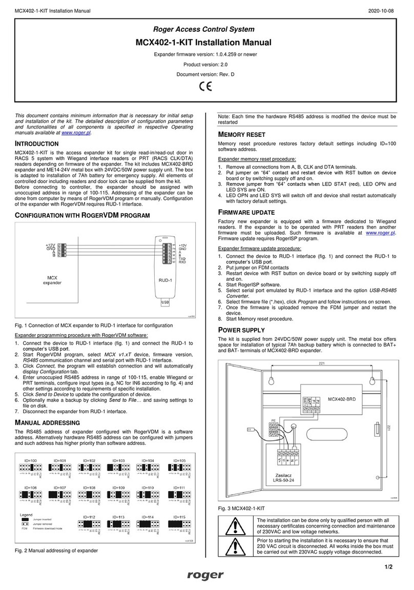
MCT68ME-IO Installation Manual 2022-05-13
1/2
Roger Access Control System
MCT68ME Installation Manual
Firmware version: 2.1.0.306 and newer
Document version: Rev. B
This document contains minimum information that is necessary for initial setup
and installation of the device. The detailed description of configuration
parameters and functionalities is specified in respective Operating manual
available at www.roger.pl.
INTRODUCTION
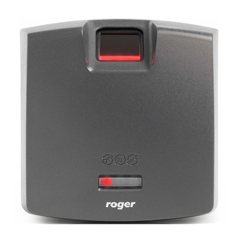
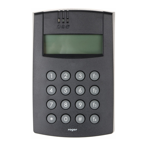
The reader is designed for operation with MC16 access controller (RACS 5
system). Factory new reader is configured with default settings including ID=100
address. MCT68ME reader is available in indoor and outdoor versions. The latter
one is equipped with additional, protecting metal enclosure.
DEVICE CONFIGURATION
The reader can be configured in regard of various parameters (including
address) in order to adapt it to the requirements of specific installation. Device
can be configured from VISO v2 management software or RogerVDM utility
software.
CONFIGURATION WITH VISO V2PROGRAM
In RACS 5 v2 system the reader can be installed at site without previous
configuration. According to AN006 application note, its address and other
settings can be configured from VISO v2 management software and during such
configuration the access to its service contacts (fig. 2) is not required.
CONFIGURATION WITH ROGERVDM PROGRAM
Fig. 1 Connection of MCT terminal to RUD-1 interface
Programming procedure:
1. Connect the device to RUD-1 interface (fig. 1) and connect the RUD-1 to
computer’s USB port.
2. Start RogerVDM program, select MCTdevice, firmware version, RS485
communication channel and serial port with RUD-1 interface.
3. Click Connect, the program will establish connection and will automatically
display Configuration tab.
4. Enter unoccupied RS485 address in range of 100-115 and other settings
according to requirements of specific installation.
5. Click Send to Device to update the configuration of device.
6. Optionally make a backup by clicking Send to File… and saving settings to
file on disk.
7. In the top menu select Device->Disconnect.
8. Disconnect device from RUD-1 interface.
Note: Do not read any cards nor press reader keypad when reader is configured
with RogerVDM.
MEMORY RESET
Memory reset procedure enables configuration of RS485 address and resets all
other settings to factory default ones.
Memory reset procedure:
1. Remove all connections from A and B lines.
2. Place jumper on MEM contacts (fig. 2)
3. Restart the device (switch power supply off and on or short RST contacts for
a moment).
4. When ‘CONFIG RESET’is displayed by reader then remove jumper from
MEM contacts.
5. When ‘ID:’ is displayed by reader then enter 3 digits of RS485 address in
range of 100-115 with reader keypad.
6. When the third digit is defined then the reader will restart with the new
address.
FIRMWARE UPDATE
The update requires connection of reader to computer with RUD-1 interface
(fig. 1) and starting RogerISP software. The latest firmware file is available at
www.roger.pl.
Firmware update procedure:
1. Connect the reader to RUD-1 interface (fig. 1) and connect the RUD-1 to
computer’s USB port.
2. Place jumper on FDM contacts (fig. 2).
3. Restart the reader (switch power supply off and on or short RST contacts for
a moment).
4. Start RogerISP program.
5. Select serial port with RUD-1 interface and USB-RS485 Converter option.
6. Specify path to firmware file (*.hex).
7. Click Program and proceed according to displayed messages.
8. Remove jumper from FDM contacts and restart the reader.
APPENDIX
Fig. 2 Service contacts
Table 1. Terminals
Screw terminal
Description
12V
Supply plus
GND
Ground
IN1
IN1 input line
IN2
IN2input line
IN3
IN3 input line
RS485 A
RS485 bus, line A
RS485 B
RS485 bus, line B
CLK
Not used
DTA
Input/output line
TMP
Tamper contact
TMP
Tamper contact
IO1
IO1 output line
IO2
IO2 output line
REL1-NC
REL1 relay output (NC)
REL1-COM
REL1 relay common terminal
REL1-NO
REL1 relay output (NO)
MCT68ME-IO Installation Manual 2022-05-13
2/2
Fig. 3 Connection of readers and expanders to MC16 access controller
Fig. 4 Connection of door lock, door contact and exit button to MCTxx-IO
terminal
Table 2. Specification
Supply voltage
Nominal 12VDC, min./max. range 10-15VDC
Current consumption
(average)
~100 mA
Inputs
Three NO/NC inputs (IN1..IN3) internally

connected to the power supply plus through a
15kΩ resistor, approx. 3.5V triggering level
Relay output
Relay output (REL1) with single NO/NC contact,
30V/1.5A DC/AC max. load
Transistor outputs
Two (IO1, IO2) open collector outputs,
15VDC/150mA max. load
DTA input/output
I/O line configured as NO/NC input or open
collector output with 15VDC/15mA max. load
Tamper protection
Isolated 24V/50mA contacts, shorted when
enclosure is closed
Proximity cards
EM 125 kHz UNIQUE according to EM4100/4102
and 13.56MHz according to ISO14443A and
MIFARE
Reading range
Up to 10 cm for EM125kHz
Up to 7 cm for MIFARE
Distance
1200m maximal cable length for RS485 bus
between controller and reader
IP Code
MCT68ME-IO-I: IP41
MCT68ME-IO-O: IP54
Environmental class
(according to EN 50133-1)
MCT68ME-IO-I:
Class I, indoor general conditions,
temperature: +5°C to +40°C, relative humidity:
10 to 95% (no condensation)
MCT68ME-IO-O:
Class IV, outdoor general conditions,
temperature: -25°C to +60°C, relative humidity:
10 to 95% (no condensation)
Dimensions H x W x D
MCT68ME-IO-I: 170 x 110 x 42 mm
MCT68ME-IO-O: 220 x 156 x 104 mm
Weight
MCT68ME-IO-I: ~410g
MCT68ME-IO-O: ~1150g
Certificates
CE
This symbol placed on a product or packaging indicates that the
product should not be disposed of with other wastes as this may
have a negative impact on the environment and health. The user is
obliged to deliver equipment to the designated collection points of
electric and electronic waste. For detailed information on recycling,
contact your local authorities, waste disposal company or point of
purchase. Separate collection and recycling of this type of waste
contributes to the protection of the natural resources and is safe to
health and the environment. Weight of the equipment is specified in
the document.
Contact:
Roger Sp. z o. o. sp. k.
82-400 Sztum
Gościszewo 59
Tel.: +48 55 272 0132
Fax: +48 55 272 0133
Tech. support: +48 55 267 0126
E-mail: support@roger.pl
Web: www.roger.pl

Other manuals for MCT68ME-IO

1

This manual suits for next models

3

Other Roger IP Access Controllers manuals

Roger PR622 User manual

Roger

Roger PR622 User manual

Roger MCT82M-IO-CH User manual

Roger

Roger MCT82M-IO-CH User manual

Roger MCT80M-BLE User manual

Roger

Roger MCT80M-BLE User manual

Roger MCT68ME User manual

Roger

Roger MCT68ME User manual

Roger PR311 Installation guide

Roger

Roger PR311 Installation guide

Roger MCT82M-IO-HR-F User manual

Roger

Roger MCT82M-IO-HR-F User manual

Roger PR402 User guide

Roger

Roger PR402 User guide

Roger RFT1000 User manual

Roger

Roger RFT1000 User manual

Roger PR602LCD-DT-I User manual

Roger

Roger PR602LCD-DT-I User manual

Roger MC16 User manual

Roger

Roger MC16 User manual

Roger PR411DR User manual

Roger

Roger PR411DR User manual

Roger MCT84M-BK-QB User manual

Roger

Roger MCT84M-BK-QB User manual

Roger PR201 Assembly instructions

Roger

Roger PR201 Assembly instructions

Roger PR402DR User manual

Roger

Roger PR402DR User manual

Roger RFT1000 Use and care manual

Roger

Roger RFT1000 Use and care manual

Roger OSR88M-IO User manual

Roger

Roger OSR88M-IO User manual

Roger MC16-PAC-1-KIT User manual

Roger

Roger MC16-PAC-1-KIT User manual

Roger PR402DR User manual

Roger

Roger PR402DR User manual

Roger MCT86M-IO-HR-CH User manual

Roger

Roger MCT86M-IO-HR-CH User manual

Roger MCX2 User manual

Roger

Roger MCX2 User manual

Roger MCX402-BRD User manual

Roger

Roger MCX402-BRD User manual

Roger MCX102-BRD User manual

Roger

Roger MCX102-BRD User manual

Roger MC16-PAC-1-KIT User manual

Roger

Roger MC16-PAC-1-KIT User manual

Roger RKD32 User manual

Roger

Roger RKD32 User manual

Popular IP Access Controllers manuals by other brands

Nidac 2 Series instructions

Nidac

Nidac 2 Series instructions

Software House PSX Series installation manual

Software House

Software House PSX Series installation manual

Chamberlain CAPXL Quick start guides

Chamberlain

Chamberlain CAPXL Quick start guides

Carrier Supra iBox BT LE user guide

Carrier

Carrier Supra iBox BT LE user guide

Amano Nexus Lite quick start guide

Amano

Amano Nexus Lite quick start guide

Fermax 5226 Installer manual

Fermax

Fermax 5226 Installer manual

Spiderdoor S14c installation guide

Spiderdoor

Spiderdoor S14c installation guide

VisAccess VXS-10 User and installation guide

VisAccess

VisAccess VXS-10 User and installation guide

IRIS ID IrisAccess iCAM7100S Series Hardware guide

IRIS ID

IRIS ID IrisAccess iCAM7100S Series Hardware guide

IDTECK FINGER007 Series troubleshooting guide

IDTECK

IDTECK FINGER007 Series troubleshooting guide

Eclipse Security ECL-IP3D50V2R user manual

Eclipse Security

Eclipse Security ECL-IP3D50V2R user manual

Pegasus PP-3702/T Series Operational manual

Pegasus

Pegasus PP-3702/T Series Operational manual

CS Technologies ACE-ATM Installation and operation

CS Technologies

CS Technologies ACE-ATM Installation and operation

PreCise Biometrics Precise 100 A quick reference

PreCise Biometrics

PreCise Biometrics Precise 100 A quick reference

fadini SAPE 69 instruction manual

fadini

fadini SAPE 69 instruction manual

2M Technology 2MTHFR-2M quick guide

2M Technology

2M Technology 2MTHFR-2M quick guide

xpr DINMTPX-EH user manual

xpr

xpr DINMTPX-EH user manual

Akuvox A05 Series Administrator's guide

Akuvox

Akuvox A05 Series Administrator's guide

manuals.online logo
manuals.online logoBrands
  • About & Mission
  • Contact us
  • Privacy Policy
  • Terms and Conditions

Copyright 2025 Manuals.Online. All Rights Reserved.