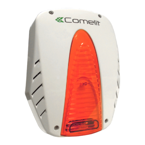
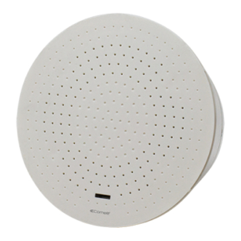
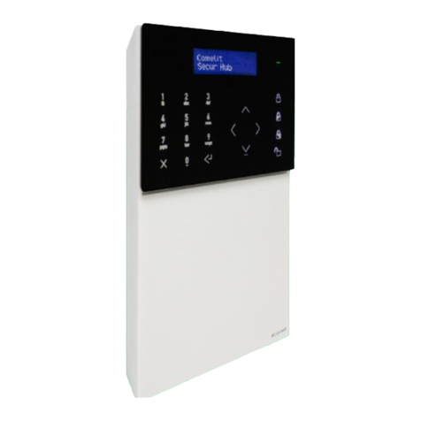
Comelit VEDO User guide

Passion.Technology.Design.
EN
SYSTEM
MANUAL
Vedo system 2.12.x

2
000P1515XXXXXXXX
Via Don Arrigoni, 5
24020 Rovetta (BG) - Italy
PCBVEDO68
Warning
• Cut off the power supply before carrying out any maintenance work.
• It is recommended to check the correct operation of the safety system
periodically (at least once a month).
• Remove any dust accumulated in the control panel housing with a damp
cloth, without using any solvent, and check that there are no foreign bodies.
• Check the condition of the connectors and the conductors.
• Carry out the maintenance and operation test of all the components (smoke
sensors, movement sensors, ...) as indicated in the respective technical
manuals.
• Replace the protections on the terminals.
• Any battery maintenance/replacement procedures should only be carried
out by trained and qualified personnel.
• All the products comply with the requirements of the 2014/30/EU and 2014/35/
EU directives. This is proved by the CE mark on the products themselves.
• The device complies with the following standards:
• EN 62368-1 relating to the safety of information technology equipment.
• EN50130-4 relating to Alarm systems Part 4: Electromagnetic compatibility
• EN50131 relating to Alarm systems - Intruder and Hold-Up alarm systems
• EN50136 relating to Alarm systems - Alarm transmission systems and
equipment
• All items have an ID label for product traceability. Two examples are shown
below:
• All the system components must have safety grade 2 or higher to obtain grade
2 alarm system certification according to standard EN50131.
Service
Certifications
Product labels
Control panel identification label
interpretation serial number: 000PWWYYXXXXXXXX
protocol number
date of manufacture
week of manufacture (WW)
and year of manufacture (YY)
(in the sample label
1515= week 15 of the year 15)
product code
000P1515XXXXXXXX
Via Don Arrigoni, 5 - 24020 Rovetta (BG) - Italy
VEDOGSM
EAN code
identifying the
product
manufacturer's name
serial number
product code
"XX" represents all control panels of the same type
For every type of control panel (VEDO10, VEDO34, VEDO34M, VEDO68,
VEDO68M), there are different language versions, identified by a code. To keep
things simple, in the manual the control panels are only referred to as VEDO10,
VEDO34, VEDO34M, VEDO68, VEDO68M. The full product code will appear on
the traceability label (e.g. VEDO34MEN)
for Italian XX = "" (e.g. VEDO34M)
for English XX = EN (e.g. VEDO34MEN)
for French XX = FR (e.g. VEDO34MFR)
for Dutch XX = NL (e.g. VEDO34MNL)
for Spanish XX = ES (e.g. VEDO34MES)
EN 50131-1
EN 50131-3
EN 50131-6
EN 50131-10
EN 50136-1
EN 50136-2
(SP4/DP3)
EN 62368-1
Grade 2 / Class II
VEDO34MXX
Max Current 0,6A
~
Vin:230V +10% -15% 50/60Hz
TA-BBBB
Certification ID code
• This Comelit product has been designed and manufactured for use in the
creation of security and automation systems in residential, commercial,
industrial and public buildings.
• All activities connected to the installation of Comelit products must be
carried out by qualified technical personnel, with careful observation of the
indications provided in the manuals / instruction sheets supplied with those
products.
• Disconnect the power supply before carrying out any operations on the
wiring.
• Use wires with a cross-section suited to the distances involved, observing
the instructions provided in the system manual.
• The wires used must comply to reference standards: IEC 60332-1-2 for wires
with a cross-section of 0.5 mm² or greater and IEC 60332-2-2 for those with
a cross-section under0.5 mm².
• We advise against running the system wires through the same duct as power
cables (230V or higher).
• To ensure Comelit products are used safely: carefully observe the indications
provided in the manuals / instruction sheets; make sure the system created
using Comelit products has not been tampered with / damaged.
• Comelit products do not require maintenance aside from routine cleaning,
which should be carried out in accordance with the indications provided
in the manuals /instruction sheets. Any repairs must be carried out: for the
products themselves, exclusively by Comelit Group S.p.A.; for the systems,
by qualified technical personnel.
• Comelit Group S.p.A. accepts no liability for any purpose other than the
intended use, or failure to observe the indications and warnings contained
in this manual / instruction sheet. Comelit Group S.p.A. reserves the right
to change the information provided in this manual / instruction sheet at any
time and without prior notice.
• For standard-compliant installation, a suitable (two-pole) device must be
provided for isolating and protecting the mains power supply in the building's
electrical system (see diagram on page 7), in compliance with current
standards (law 46/90): for example, a two-pole overload circuit breaker
with rated current 6A. There must be a gap of at least 3 [mm] between the
isolating device contacts.
To maintain conformity of the product with current regulations, the battery used
must comply with the following requirements:
• The battery must conform to one of the following standards: IEC 60086-4,
IEC 60086-5, IEC 60896-11, IEC 60896-21, IEC 60896-22, IEC 61056-1 and
IEC 61056-2, IEC 61427, IEC/TS 61430, IEC 61434, IEC 61959, IEC 62133,
IEC 62281, and IEC 62485-2;
• The lead battery must be a VRLA (Valve Regulated Lead Acid) type;
• The battery casing flammability class must be equal to or greater than
UL94V-1.
Any battery maintenance/replacement procedures should only be carried out
by trained and qualified personnel.
Battery
GLOSSARY
ISO 7000-0434 Caution, refer to the documentation IEC 60417-5134 Devices sensitive to static electricity
ISO 3864 Caution, risk of electric shocks EEC Directive 93/42 The CE mark indicates that the product conforms to the
applicable European Union directives
ISO 7000-1641 Read the operating instructions BS EN 50419: 2006
WEEE: subject to regulations for the disposal of electrical
and electronic equipment (e.g. items that should not be
disposed of using general waste methods)
IEC 60417-5017 Earth connection IEC 60417-5031
(2002-10) Device powered with direct current
manufacturer's name
serial number

3
Table of contents
1. Introduction to the system..........................................................................................4
1.1 DESCRIPTION OF SYSTEM COMPONENTS..................................................................................4
1.2.1 Main system specifications ..................................................................................................4
1.1.1 Communication standard .....................................................................................................4
1.1.2 Addressing the modules.......................................................................................................4
1.2 GENERAL........................................................................................................................................4
1.2.2 Power supply unit technical specifications..........................................................................6
1.2.3 Power supply unit technical specifications..........................................................................7
2. Identification of parts and separation of circuits .....................................................8
2.1 POSITIONING OF COMPONENTS AND FIXTURES (FOR ART. BOXPLASTIC)..............................8
2.2 ROUTES FOR SEPARATING THE SELV CIRCUIT AND THE HIGH VOLTAGE CIRCUIT (FOR ART.
BOXPLASTIC) ...............................................................................................................................8
2.3 POSITIONING OF COMPONENTS AND FIXTURES (FOR ART. BOXMETAL).................................9
2.4 ROUTES FOR SEPARATING THE SELV CIRCUIT AND THE HIGH VOLTAGE CIRCUIT (FOR ART.
BOXMETAL) ..................................................................................................................................10
3. Technical and installation specifications...................................................................11
3.1 BOXPLASTIC...................................................................................................................................11
3.1.1 Technical specifications........................................................................................................11
3.1.2 Installation .............................................................................................................................11
3.2 BOXMETAL......................................................................................................................................11
3.2.1 Technical specifications........................................................................................................11
3.2.2 Installation .............................................................................................................................11
3.3 CONTROL PANEL BOARD ART. PCBVEDO10, PCBVEDO34, PCBVEDO68, PCBVEDO200........11
3.3.1 Main features.........................................................................................................................11
3.3.2 Technical specifications........................................................................................................12
3.4 INTERNAL EXPANSIONS................................................................................................................13
3.4.1 Telephone dialler functions (PSTN as standard)..................................................................13
3.4.2 Messages and Voice Control expansion module (Art. VEDOVOICE)..................................14
3.4.3 GSM communication expansion module (Art. VEDOGSM).................................................14
3.4.4 GSM communication expansion module (Art. VEDOGSM3G)............................................17
3.4.5 GSM communication expansion module (Art. VEDOGSM4G)............................................18
3.4.6 TCP/IP Ethernet expansion module (Art. VEDOIP)..............................................................20
3.5 GENERAL INFORMATION ABOUT CONNECTING DEVICES TO THE BUS...................................21
3.5.1 Bus line termination ..............................................................................................................21
3.6 WIRING THE INPUTS......................................................................................................................21
3.6.1 Normally closed (NC) ............................................................................................................21
3.6.2 Normally open (NO)...............................................................................................................22
3.6.3 Single balance.......................................................................................................................22
3.6.4 Double balance .....................................................................................................................22
3.6.5 Triple balance ........................................................................................................................22
3.6.6 Triple balance with jamming.................................................................................................22
3.6.7 Double zone (double)............................................................................................................22
3.6.8 Double zone with end of line (EOL double)..........................................................................22
3.6.9 Wiring the control panel's 24-hour input .............................................................................22
3.6.10 Wiring the telephone dialler on the PSTN network............................................................22
3.7 CONTROL AND DISPLAY COMPONENTS.....................................................................................23
3.7.1 LCD keypad art. VEDOKP, VEDOKP200 and keypad with RFID key reader art. VEDOKPR,
VEDOKPR200.....................................................................................................................23
3.7.2 LCD keypad art. VEDOLCD and keypad with RFID key reader art. VEDOLCDPROX ........24
3.7.3 RFID proximity reader on bus...............................................................................................24
3.7.4 RFID keys (Art. SK9050x/A) ..................................................................................................26
3.8 OTHER DEVICES THAT CAN BE CONNECTED TO THE 485 BUS.................................................26
3.8.1 Vedo Touch (Art. VEDOTOUCH) / Mini Touch (Art. 20034607) with RFID key reader ........26
3.8.2 Planux Manager with RFID key reader (Art. 20034801).......................................................27
3.8.3 Icona Manager ViP (Art. 20003310W) ..................................................................................28
3.9 EXPANSIONS ON 485 BUS ............................................................................................................29
3.9.1 Plastic expansion housing ....................................................................................................29
3.9.2 Expansion on bus with 8 balanceable inputs and 8 logic outputs on bus .........................29
3.9.3 Two-way radio expansion on bus (Art. RF10VEDO / RF32VEDO).......................................31
3.9.4 PAL/IP video module Art. VEDOCCTV .................................................................................31
3.10 WIRELESS SENSORS AND ACCESSORIES ................................................................................33
3.11 OUTPUTS SIREN CONNECTION EXAMPLES..............................................................................33
3.11.1 Connecting a self-powered siren with 3 or 2 wires ...........................................................33
3.11.2 Connecting a non-self-powered indoor siren....................................................................33
3.11.3 2-wire connection of indoor siren and self-powered siren with siren fault zone and siren
sabotage zone....................................................................................................................33
3.11.4 2-wire connection of self-powered siren with siren fault zone and siren sabotage zone .33
3.11.5 3-wire connection of self-powered siren with siren fault zone and siren sabotage zone .33
3.12 EXAMPLE OF CONNECTION TO OUTPUTS TC1 AND TC2.........................................................34
3.13 POWER SUPPLY STATIONS .........................................................................................................34
3.13.1 Power supply unit management board for Vedo series control panels Art. PCBPSU ....34
3.14 BUS ATOR (VEDOISO) ..................................................................................................................36
4. Appendix: Mounting instructions ...............................................................................37
4.1 OPENING THE HOUSING ART. BOXPLASTIC ...............................................................................37
4.2 PREPARING THE HOUSING ART. BOXPLASTIC ...........................................................................37
4.3 FIXING THE HOUSING ART. BOXPLASTIC TO THE WALL............................................................37
4.4 MOUNTING THE CONTROL PANEL BOARD ART. PCBVEDO10, PCBVEDO34, PCBVEDO68,
PCBVEDO200, PCBPSU IN HOUSING ART. BOXPLASTIC .........................................................38
4.6 MOUNTING THE EXPANSION ART. VEDO8I8O E RF10VEDO, RF32VEDO IN HOUSING ART.
BOXPLASTIC ................................................................................................................................38
4.5 MOUNTING THE POWER SUPPLY UNIT PSU15 IN A HOUSING ART. BOXPLASTIC ..................38
4.7 OPENING THE HOUSING ART. BOXMETAL...................................................................................39
4.8 FIXING THE HOUSING ART. BOXMETAL TO THE WALL...............................................................39
4.9 MOUNTING THE CONTROL PANEL BOARD ART. PCBVEDO10 / PCBVEDO34 / PCBVEDO68 /
PCBVEDO200 AND PCBPSU IN HOUSING ART. BOXMETAL.....................................................40
4.10 MOUNTING THE EXPANSION ART. VEDO8I8O IN HOUSING ART. BOXMETAL.........................40
4.11 MOUNTING THE POWER SUPPLY UNIT PSU15 - PSU50 IN A HOUSING ART. BOXMETAL.....40
4.12 MOUNTING THE MODULE ART. VEDOCCTV IN METAL HOUSING............................................41
4.13 MOUNTING THE MODULE ART. 30076003 / 30076004 IN METAL HOUSING............................41
4.14 MOUNTING THE KEYPAD ART. VEDOKP, VEDOKP200, VEDOKPR, VEDOKPR200 IN BOX 503.....
42
4.15 SURFACE-MOUNTING THE KEYPAD ART. VEDOKP, VEDOKP200, VEDOKPR, VEDOKPR200 .42
4.16 MOUNTING THE VEDO TOUCH / MINI TOUCH (ART. 20034607) IN BOX 503 ...........................43
4.17 MOUNTING PLANUX MANAGER (ART. 20034801) WITH FLUSH-MOUNTED BOX ART. 6117 ..44
4.18 MOUNTING PLANUX MANAGER (ART. 20034801) WITH WALL BRACKET ART. 6120 ..............45
4.19 WALL-MOUNTING ICONA MANAGER VIP / MOUNTING IN 503 SERIES BOX / ROUND BOX ..46
4.20 MOUNTING ICONA VIP MANAGER IN A FLUSH-MOUNTED BOX ART. 6117 ............................47
4.21 PREPARING THE PLASTIC HOUSING FOR MOUNTING THE EXPANSION ART. RF10VEDO /
RF32VEDO / VEDO8I8O................................................................................................................48
4.22 WALL-MOUNTING THE PLASTIC HOUSING FOR EXPANSION ART. RF10VEDO / RF32VEDO /
VEDO8I8O.....................................................................................................................................48
5. Appendix: notes on installation and programming...................................................49
5.1 WHAT TO DO BEFORE POWERING UP THE SYSTEM..................................................................49
5.1.1 Connect the zone inputs correctly .......................................................................................49
5.1.2 Connect the bus modules.....................................................................................................49
5.1.3 Close all the anti-tamper inputs ...........................................................................................49
5.1.4 Powering up ..........................................................................................................................49
5.2 DEFAULT CONFIGURATION ...........................................................................................................49
5.3 INTRODUCTION TO PROGRAMMING FROM THE KEYPAD .........................................................49
5.3.2 Default codes ........................................................................................................................49
5.3.3 Keypad navigation mode......................................................................................................49
5.3.4 Modifying a numerical value................................................................................................. 49
5.3.5 Editing an alphanumeric string.............................................................................................49
5.3.6 Setting the keypad serial number ........................................................................................49
5.3.7 Total arming of the alarm system .........................................................................................50
5.3.8 Partial activation of the alarm system / execution of a scenario........................................50
5.3.9 Total deactivation of the alarm system ................................................................................50
5.3.10 Silencing an alarm with the system deactivated ...............................................................50
5.3.11 Entering programming as a User .......................................................................................50
5.3.12 Entering programming as an Installer (installer code authorisation)................................50
5.3.13 Changing date and time .....................................................................................................50
5.3.14 Acquiring an RFID key code from the keypad...................................................................50
5.3.15 Acquiring a radio sensor code from the keypad ...............................................................50
5.3.16 Acquiring a radio control code from the keypad...............................................................50
5.3.17 Acquiring a siren code from the keypad............................................................................51
5.3.18 Exiting programming mode................................................................................................51
5.3.19 Restoring factory settings...................................................................................................51
5.3.20 Setting the control panel to Service Status .......................................................................51
5.3.21 Exiting Service Status .........................................................................................................51
5.4 FAST NAVIGATION OF KEYPAD MENU (INSTALLER AND USER) .................................................51
5.5 CONFIGURATIONS NECESSARY TO GUARANTEE GRADE 2 CERTIFICATION ACCORDING TO
EN50131-1 (SP2-DP1) ..................................................................................................................52
5.5.1 Keypads.................................................................................................................................52
5.5.2 Touch .....................................................................................................................................52
5.5.3 App ........................................................................................................................................ 52
5.5.4 Home automation system manager.....................................................................................52
5.5.5 Input/output expansions (8I8O) ............................................................................................ 52
5.5.6 Power supply stations...........................................................................................................52
5.5.7 Isolators .................................................................................................................................53
5.5.8 Radio expansion....................................................................................................................53
5.5.9 Radio outputs........................................................................................................................53
5.5.10 Radio controls .....................................................................................................................53
5.5.11 Radio zones.........................................................................................................................53
5.5.12 Wired zones.........................................................................................................................53
5.5.13 Areas....................................................................................................................................54
5.5.14 Wired outputs......................................................................................................................54
5.5.15 User .....................................................................................................................................54
5.5.16 Installers ..............................................................................................................................54
5.5.17 IP Options ...........................................................................................................................54
5.5.18 GSM settings.......................................................................................................................54
5.5.19 Transmission Options..........................................................................................................54
5.5.20 Phone Book / Email ............................................................................................................55
5.5.21 Digital dialler contacts list ..................................................................................................55
5.5.22 Generic events ....................................................................................................................55
5.5.23 Detailed events....................................................................................................................55
5.5.24 Service voice messages .....................................................................................................56
5.5.25 Timer Types .........................................................................................................................56
5.5.26 Timer Model .......................................................................................................................57
5.5.27 System Parameters.............................................................................................................57
5.5.28 Events to be saved..............................................................................................................57
5.6 CONFIGURATIONS NECESSARY TO GUARANTEE INCERT CERTIFICATION .............................58
5.6.1 Code type ..............................................................................................................................58
5.6.2 System Parameters ..............................................................................................................58
5.7 OFFICIAL SYMBOL CONVENTIONS FOR ANTI-INTRUSION SYSTEMS.......................................58
5.8 SHIELDED CABLE CONDUCTOR RESISTANCE TABLE ................................................................58
5.8.1 Input and signal connections ...............................................................................................58
5.8.2 Power supply connections ...................................................................................................59
5.9 DATA NETWORK CONNECTION CABLE........................................................................................59

4
1. Introduction to the system
Vedo is a modern, practical I&HAS (Intrusion and Hold Up alarm system)
capable of meeting the technical and performance requirements of modern
security systems to the best effect. The Vedo system allows the creation of
systems that require up to 200 individual standard zones with double or triple
balance, which can be assigned to a maximum of 16 areas.
The system integrates home automation functions that do not influence the
behaviour of the alarm system.
The control panel is enclosed in a compact housing, which also accommodates
the power supply unit. Depending on system requirements, it is possible to
equip the control panel board directly with a module for GSM communication,
a messages / voice control module and a module for communication over IP
protocol. The connectors for powering the control panel are routed from the
power supply unit.
Inside the metal housings it is possible to accommodate 2 standard input/
output expansions. In the plastic housings it is possible to fit 2 8IO expansion
modules or 1 8IO expansion module and a radio expansion. The expansion
modules are connected to the Bus.
The system comprises a master unit (the control panel) and a certain number of
slave units (the peripherals on the Bus). Regardless of system activation status,
the control panel's task is to query the peripheral units periodically to determine
correct operation and obtain information about system status. Each peripheral
component is equipped with local intelligence, which enables it to perform a
certain number of tasks independently and, at the request of the control panel,
communicate its status and any information relating to its specific peripheral
functions.
Communication between the control panel and the expansions takes place by
means of a standard RS485 Bus. The control panel's standard communication
speed is set to 38400 baud.
The modules are all connected to the same Bus, and are recognisable by their
unique address. Depending on the peripheral, this address can be configured
by physical means (e.g. DIP-switches, as on the input and output expansions)
or by means of software configuration (e.g. LCD keypads).
The control panel is supplied with a built-in digital dialler.
The control panel can be programmed directly from the keypad or, more easily,
by means of dedicated software. The audio messages can be modified only by
using the programming software from a PC.
The association of zones to areas and partial subgroups of areas allows total,
partial or selective activation of the system, according to the authorisations
assigned (at the configuration stage) to the user who performs the operations.
Each input event can be associated with multiple outputs, thus potentially
involving all the outputs configured at the installation stage. The flexibility of
this arrangement makes it possible to adapt the control panel to the most wide-
ranging requirements.
1.1 DESCRIPTION OF SYSTEM COMPONENTS
______________________________________________________________________
1.2 GENERAL
1.1.1 Communication standard
1.1.2 Addressing the modules
INPUTS / OUTPUTS / BALANCING
VEDO10 VEDO34 VEDO34M VEDO68 VEDO68M VEDO200 VEDO200M
Control panel inputs 8 + 1 24h
Maximum Number of Inputs
18
(2wire+8radio)
(max 16 radio)
34 (mixed) 34 (mixed) 68 (64Radio) 68 (64Radio) 200 200
Control Panel Outputs 3: 1 relay 3A@24V + 2oc 100mA
Maximum Number Outputs (wired +radio) 16 36 36 50 50 100 100
Double Function No Yes Yes Yes Yes Yes Yes
Balance Type
NO, NC,
Single,
Double,
Triple, Triple
with jamming
NO, NC, Single, Double, Triple, Triple with jamming, Double zone, Double zone with end of
line
PROGRAMMING / MAINTENANCE
VEDO10 VEDO34 VEDO34M VEDO68 VEDO68M VEDO200 VEDO200M
Programming/Reading of options in local/
remote mode Yes
Control panel programming USB/LAN
Programming from Keypad or Vedo Touch with
emulated keypad Yes
Programmable test call Yes
Remote maintenance Yes with IP card
Periodic test call Yes on digital dialler
USER CODES / KEYS / REMOTE CONTROLS
VEDO10 VEDO34 VEDO34M VEDO68 VEDO68M VEDO200 VEDO200M
User Code 8 32 32 50 50 200 200
Installer Code 255555 5
Manufacturer Code 1
Remote controls 11 38 38 56 56 64 64
Keys 11 38 38 56 56 200 200
COMPATIBLE DEVICES / NUMBER OF DEVICES SUPPORTED
VEDO10 VEDO34 VEDO34M VEDO68 VEDO68M VEDO200 VEDO200M
Plastic housing Yes Ye s No Yes No Yes No
Metal housing No No Yes No Yes No Yes
Power supply unit PSU15 PSU15 PSU15
PSU50
PSU15 PSU15
PSU50
PSU15 PSU15
PSU50
Maximum number power supply stations 2448888
Number of IN/OUT expansions 0 8 8 12 12 50 50
RFID readers 2 8 8 8 8 16 16
Keypads / Keypads with proximity reader 2 (min 1)* 8 (min 1)* 8 (min 1)* 8 (min 1) 8 (min 1) 16 (min 1) 16 (min 1)
Vedo Touch with proximity reader 1224 4 4 4
Touch Devices (Mini Touch, Planux Manager,
Icona Manager ViP with proximity reader) 1228 8 8 8
Radio Receivers 1223388
√ IMPORTANT: no two components of the same type and with the
same logical address must be present on the bus. For example,
there cannot be two or more keypads with the same address.
Should this happen, the system will be unable to function correctly
and will generate a bus error.
TAB_control panel features
1.2.1 Main system specifications

5
Plug-in Audio Module Yes
Voice Menu Command Interface Yes
Plug-in GSM Module Yes
Plug-in TCP/IP Module Yes
PAL IP Module 2 4
Number of cameras managed 8 (for every PAL/IP module)
Integrated interface PSTN Yes
App Phone 8
* we recommend installing at least one keypad (Art. VEDOKP, VEDOKP200, VEDOKPR, VEDOKPR200, VEDOLCD, VEDOLCDPROX)
If 20 or more control devices are active, we recommend setting the BUS speed to 115200.
ACTIVATIONS
VEDO10 VEDO34 VEDO34M VEDO68 VEDO68M VEDO200 VEDO200M
Areas 2 8 8 8 8 16 16
Area activation modes 4 (Total, partial 1, partial 2, partial 1+2)
Partial Activations 2
Activation Programs (Scenarios) 8 8 8 16 16 32 32
Programmable Auto Activation/Deactivation Yes
Auto-activation Models (Public Holidays +
Schedules) 30 60 60
Area Exclusion for Patrol function with
automatic or manual reactivation Yes
Time programs 4 16 16 16 16 32 32
Accepts commands from telephone with tone
dialling or by SMS
Activation/Deactivation, activation/deactivation of zones, outputs, timers, Status interrogation of individual
Areas and Zones), stop alarms.
ALERTS
VEDO10 VEDO34 VEDO34M VEDO68 VEDO68M VEDO200 VEDO200M
Alert options in accordance with EN50131-1
Type A: two sirens with remote power supply + PSTN or GSM or IP dialler. The first siren connected to the
control panel relay, the second siren connected to an additional output (for example, an output on an 8IO
expansion device) via a low-consumption relay.
Type B: one self-powered siren + PSTN or GSM or IP dialler.
Type C: two active diallers, either PSTN or GSM or IP.
Text-to-Speech Audio Messages (general
events) 20 32 32 48 48 48 48
Audio message 1020 minutes
Built-in digital dialler Yes
Voice Telephone Numbers, SMS and MMS 16
Digital Telephone Numbers 4
Email addresses 16
Events Log (according to standard EN50131-1) 1024 events with date and time 4096 events with date and
time
Additional Events Log 1024 events with date and time 4096 events with date and
time
SMS and for Alarm Receiving Centres Yes
Supports the CONTACT ID protocol Yes
Supports SIA protocol (Level 1) Yes
Supports SIA-DC-09 protocol
(send events over TCP-IP channel) Ye s
Priority in processing and indicating signals
1) Alarm Events, 2) Sabotage, 3) Malfunctions, 4) Exclusions, 5) Other events
In the telephone options it is possible to set the priority for sending messages by sms, email, mms, voice,
digital
• Control panel status interrogation via SMS
• Checking residual credit of the prepaid SIM
• Transmission of Voice Messages via GSM
• Event transmission in Contact-ID and SIA (Level 1) format via GSM and
over TCP-IP (SIA-DC-09 protocol support)
• Event transmission by email with images
• Event transmission by MMS
ADDITIONAL FUNCTIONS WITH IP MODULE ART. VEDOIP
• Ethernet Interface.
• Event transmission in Contact-ID and SIA (Level 1) format over TCP-IP
(SIA-DC-09 protocol support)
• Programming and Monitoring of the control panel via LAN through Safe
Manager
• Programming and Monitoring of the control panel via Internet through Safe
Manager
• Control panel management vie Internet through Vedo App
• Event alert via email and on Vedo App with alerts with proprietary protocol
• Alert by email for alarms/malfunctions/sabotage/events with images
VARIOUS FUNCTIONS COMMON TO ALL CONTROL PANELS
• Up to 10 simultaneous connections
• Telephone access via sounder or dialler
• Telephone line status check
• Skip Answerer
• Possibility of sharing the telephone line with another answering device
• Integrated voice calls (Text To Speech)
• Telephone voice control, with remote DTMF management
• Possibility of downloading pre-recorded Text to Speech voice messages
• Function keys for alarm calls and rapid activations (available on keypad,
Mini Touch, Planux Manager, and App)
• Event transmission in Contact ID and SIA (Level 1) format
ADDITIONAL FUNCTIONS WITH GSM MODULE ART. VEDOGSM,
VEDOGSM3G AND VEDOGSM4G
• GSM850, EGSM900, DCS1800, PCS 1900 (with art. VEDOGSM)
• EGSM900, DCS1800, UMTS2100, UMTS1900, UMTS900, UMTS850 (with
art. VEDOGSM3G)
• GSM/GPRS channel support (with art. VEDOGSM)
• GSM/GPRS/UMTS/HSPA channel support (with art. VEDOGSM3G)
• GSM/GPRS/UMTS/USPA/LTE channel support (with art. VEDOGSM4G)
• Main or reserve telephone dialler
• Indication of alarms/malfunctions/sabotage/events via SMS
• Customisable SMS messages

6
VEDO10 VEDO34 VEDO34M VEDO68 VEDO68M VEDO200 VEDO200M
Dimensions (L x H x D) 260 x 280 x 80
mm
260 x 280 x 80
mm
440 x 315 x 95
mm
260 x 280 x 80
mm
440 x 315 x 95
mm
260 x 280 x
80 mm
440 x 315 x
95 mm
Weight (without battery) 1313 g 1313 g
3845 (with
PSU15)
4039 (with
PSU50)
1313 g
3845 (with
PSU15)
4039 (with
PSU50)
1313 g
3845 (with
PSU15)
4039 (with
PSU50)
Power supply units supported PSU15 PSU15 PSU15
PSU50 PSU15 PSU15
PSU50 PSU15 PSU15
PSU50
Batteries supported Art. 30076003
12 V/7 Ah
Art. 30076003
12 V/7 Ah
Art. 30076003
12 V/7 Ah
Art. 30076004
12 V and 18 Ah
Art. 30076003
12 V/7 Ah
Art. 30076003
12 V/7 Ah
Art. 30076004
12 V and 18 Ah
Art.
30076003
12 V/7 Ah
Art.
30076003
12 V/7 Ah
Art.
30076004
12 V and
18 Ah
Max. battery charging current 0.8A
Battery 80% charging time 8h 8h 8h/19h 8h 8h/19h 8h 8h/19h
Low Battery Fault Generation in
presence of EPS 12 V
Low Battery Fault Generation in
absence of EPS 11.5 V
Low output voltage fault on power
supply unit 12.8 V
Control panel switch-o in absence
of EPS for Protection against
deep discharges (the battery is
disconnected to avoid damage)
10.5 V
Maximum current for V+SIR outputs 0.75A
Intervention voltage of the protection
against voltage surges: battery
disconnection
15 V
Maximum current for V+bus,V+AUX
outputs 1.5A
Output voltage operating range (Vbus,
VAUX1, VAUX2) 10 ~ 15 V
CN1 input voltage operating range 12.8 ~ 15 V
CN2 input voltage operating range
(Battery) 10.5 ~ 15 V
Control panel board consumption
(min./max.)
Control panel in standby: 50 mA +
All active outputs: 40 mA +
PSTN active and communicating: 35 mA +
Audio: 1 mA +
VEDOGSM: 10 mA idle, 35 mA communicating / VEDOGSM (protocol >= 004): 10 mA idle, 60 mA communicating /
VEDOGSM3G: 10 mA idle, 90 mA communicating + IP: 55 mA / VEDOGSM4G: 36 mA in Idle,
80 mA when communicating
Average power consumption in 1 h:
PCBVEDOXX 90 mAh 1 alarm every 5 minutes and communication with duration of 3 minutes.
VEDOGSM (protocol <= 004) 24 mAh 1 alarm every 5 minutes and communication with duration of 2 minutes.
VEDOGSM (protocol >= 004) 20 mAh 1 alarm every 5 minutes and communication with duration of 1 minute.
VEDOGSM3G: 26 mAh 1 alarm every 5 minutes and communication with duration of 1 minute.
VEDOGSM3G: 43 mAh 1 alarm every 5 minutes and communication with duration of 1 minute
VEDOIP 55 mAh 1 alarm every 5 minutes and communication with duration of 1 minute.
Maximum consumption (with audio
module, IP module active and
connected, GSM module transmitting)
Control panel in alarm status with all expansions active: 216 mA (with VEDOGSM)
Control panel in alarm status with all expansions active: 241 mA (with VEDOGSM - with protocol >= 004)
Control panel in alarm status with all expansions active: 271 mA (with VEDOGSM3G)
Control panel in standby with all expansions active: 116 mA
Maximum current available for
external devices
Depends on the control panel configuration
(see “Maximum current available for external devices on the basis of the control panel configuration” table on page
7)
1.2.2 Power supply unit technical specifications
Technical specifications complying with standard EN50131-6 (new standard which establishes the required performances of a power supply unit in alarm
systems).
ATS CATEGORIES BASED ON CONFIGURATIONS
The Vedo control panels equipped with transmission devices (integrated or optional extras) listed in the table below are SPTs (Supervised Premises Transceiver)
which interface with the alarm system and transmit alarms via various networks.
SPT CONFIGURATION ATS CATEGORY
PCBVEDOXX(PSTN) VEDOGSM/VEDOGSM3G
VEDOGSM4G
VEDOIP SINGLE PATH DUAL PATH
Primary interface
PSTN √SP2
PSTN or GSM √ √ SP2 DP1
PSTN or email IP √ √ SP2 DP1
PSTN or GSM or email IP √√ √ SP2 DP1
GSM √SP2
email IP √SP2
GSM or email IP √ √ SP2 DP1
DIGIT. GSM COMM. √SP4
DIGIT. IP COMM. √SP4
DIGIT. GSM or IP COMM. √ √ SP4 DP3
with SIA-DCS IP or Contact ID IP, with encryption key and transmission time <= 3 min.

7
* Observing any indications for configuration and installation
Power supply unit versions PSU15 PSU50
Name of manufacturer / supplier Comelit Group S.p.A. Comelit Group S.p.A.
Dimensions (L x H x D) 78 x 110 x 36 mm 98 x129 x40 mm
Weight 241 g 435 g
Input voltage 230 V~ + 10% -15%
AC input frequency 50/60 Hz
AC Alternating Current @230 V~ : 0.6A @230 V~ : 1.3A
Output voltage 14.0 V ± 2% 14.0 V ± 2%
Rated current 1.5A Max 5A Max
Output voltage ripple 300 mV
Voltage surge protection +50%
Overload protection 110~180% rated output power
Operating temperature and Operating humidity -10° / + 55° with warm dry air
-10° / + 40°C with max + 93% RH (not condensed)
Safety grade 2 according to EN50131-1*
Environmental class II according to EN50131-1
1.2.3 Power supply unit technical specifications
* Observing any indications for configuration and installation
EXAMPLE OF TWO-POLE ISOLATING DEVICE
Control
panel
PHASE
230 V
50 Hz
NEUTRAL
EARTH
Wiring diagram: two-pole mains switch (for example overload circuit breaker with rated
current 6A) able to isolate the power supply of the device. There must be a gap of at least 3
[mm] between the isolating device contacts.
FIG_system isolation
Art. PSU15 / PSU50 conforms to standards EN50130-4:2011, EN 62368-1/A1:2018
The control panel is certified up to grade 2 according to standard
EN50131-1. It is possible to maintain grade 2 system certification only if
the system consists of components of grade II or higher.
Products certified with safety grade 2 according to standard EN50131-1:
Housings: Art. BOXPLASTIC, BOXMETAL
Control panel boards: Art. PCBVEDO10, PCBVEDO34, PCBVEDO68
Internal expansions: Art. VEDOVOICE, VEDOGSM, VEDOGSM3G,
VEDOIP
Keypads and activators: Art. VEDOLCD, VEDOLCDPROX
Expansions on 485 bus: Art. VEDO8I8O
Power supply units: Art. PSU15, PSU50
Isolators: Art. VEDOISO
MAXIMUM CURRENT AVAILABLE FOR EXTERNAL DEVICES ON THE BASIS OF THE CONTROL PANEL CONFIGURATION
POSSIBLE CONFIGURATIONS CONTROL PANELS
BATTERY POWER SUPPLY
UNIT MAXIMUM CURRENT VEDO10 VEDO34 VEDO34M VEDO68 VEDO68M VEDO200 VEDO200M
30076004
12 V and
18Ah
PSU50 1500 mA for EN 50131-6:2017
750 mA for T031:2017
(- mean current absorbed by the
control panel)
√ √ √
30076004
12 V and
18Ah
PSU15 700 mA for EN 50131-6:2017
700 mA for T031:2017
(- mean current absorbed by the
control panel)
√ √ √
30076003
12 V and
7Ah
PSU15 580 mA for EN 50131-6:2017
290 mA for T031:2017
(- mean current absorbed by the
control panel)
√√√√√√ √
30076003
12 V and
7Ah
PSU50 580 mA for EN 50131-6:2017
290 mA for T031:2017
(- mean current absorbed by the
control panel)
√ √ √
VEDO10 VEDO34 VEDO34M VEDO68 VEDO68M VEDO200 VEDO200M
Maximum current delivered to outputs
TC1 and TC2 100 mA
Relay contacts capacity in output
switching NO-COM-NC 3A @ 24V
Operating temperature and Operating
humidity
-10° / + 55° with warm dry air
-10° / + 40°C with max + 93% RH (not condensed)
Safety grade 2 according to EN50131-1 * not certified
Type of power supply unit TYPE A according to standard EN50131-6
Environmental class II according to EN50131-1 not certified

8
12
8
8
9
8
7
1
14
5
1
3
A
B
C
DF E
6
A1
A2
A3
2 3 41
12
11
10
13
7
5
6
9
8
10
2. Identification of parts and separation of circuits
2.1 POSITIONING OF
COMPONENTS AND
FIXTURES (FOR ART.
BOXPLASTIC)
2.2 ROUTES FOR
SEPARATING THE
SELV CIRCUIT AND
THE HIGH VOLTAGE
CIRCUIT (FOR ART.
BOXPLASTIC)
1. Holes for fixing the housing
2. Clips for fixing the control panel board
Art. PCBVEDO10 - PCBVEDO34
- PCBVEDO68 - PCBVEDO200 -
PCBPSU
3. Clip for fixing expansion Art.
VEDO8I8O
4. Housing of fixing screw for power
supply unit Art. PSU15
5. Clip for fixing battery Art. 30076003
6. Position of control panel identification
label
7. Anti-tear tamper hole
8. Cable routing holes
9. Clip for fixing expansion Art.
RF10VEDO / RF32VEDO / VEDO8I8O
1. VEDOIP expansion network connector
2. Expansion antenna connector Art.
VEDOGSM / VEDOGSM3G
3. Battery connector
4. PSU connector
5. Control panel board power supply
connections
6. Fixing screw for power supply unit
PSU15
7. Internal fuse 250 V~ T2A (for Art.
PSU15), Internal fuse 250 V~ T2.5A
(for PSU50)
8. Cable for connecting the power
supply unit to earth Art. PSU15
9. High Voltage Cables
10.Cable for connecting the control
panel board to earth Art. PCBVEDO10
- PCBVEDO34 - PCBVEDO68 -
PCBVEDO200
11.Balance resistor
12.GSM Antenna
13.Tamper connectors
A. Control panel board position
Art. PCBVEDO10 - PCBVEDO34
- PCBVEDO68 - PCBVEDO200 -
PCBPSU
B. Expansion position Art. VEDO8I8O
C. Power supply unit position Art.
PSU15
D. Battery position Art. 30076003
E. Tamper position
F. Expansion position Art. RF10VEDO /
RF32VEDO / VEDO8I8O
A1.Position of communication module
VEDOGSM / VEDOGSM3G / VEDOGSM4G
A2.Position of messages expansion VEDOVOICE
A3.Position of IP module VEDOIP
For standard-compliant
installation, pay attention to the
correct route of the earthing
cables and of the SELV circuit
and high voltage cables.
When fixing the product to
the wall, use the 5 wall plugs
supplied: FISCHER SX 6 S
ART.570021.

9
1 3 a b43
4
8
9
10
11
313 12 3
6
AB
C
E
D
F
G
2 52
7
7
5
1. GSM antenna output
2. Supports for fixing the control
panel board Art. PCBVEDO10
- PCBVEDO34 - PCBVEDO68 -
PCBVEDO200 - PCBPSU
3. Holes for fixing the housing
4. Cable routing holes
5. Supports for fixing ( ) and holding
expansion Art. VEDO8I8O
6. Anti-tear Tamper hole
7. Screws for fixing ( ) and holding PAL
module Art. VEDOCCTV
8. Supports for fixing power supply unit
9. Anti-sabotage protection panel
10.Inlet holes for power supply unit
locking clamp
11.Position of control panel identification
label
12.Housing of fixing screw for power
supply unit Art. PSU50
13.Housing of fixing screw for power
supply unit Art. PSU15
Optional positions*
a. Holes for mounting supports for fixing
the expansion Art. VEDO8I8O
b. Screws for fixing ( ) and holding PAL
module Art. VEDOCCTV
* for further information, see the manual
for Art. BOXMETAL
A. Control panel board position Art.
PCBVEDO10 - PCBVEDO34 -
PCBVEDO68 - PCBVEDO200 -
PCBPSU
B. Expansion position Art. VEDO8I8O
C. Expansion position Art. VEDO8I8O
D. Tamper position
E. Battery position Art. 30076003 /
Art.30076004
F. Power supply unit position Art.
PSU15/PSU50
G. PAL/IP module position Art.
VEDOCCTV
In order to guarantee
certification of the system it
is necessary to fix the 7 Ah
or 18 Ah battery to the metal
housing with the double-sided
tape provided (see )
2.3 POSITIONING OF
COMPONENTS AND
FIXTURES (FOR ART.
BOXMETAL)
When fixing the product to
the wall, use the 5 wall plugs
supplied: FISCHER SX 6 S
ART.570021.

10
C
D
B
A
2 4 631 5
A1
A2
A3
8
9
11 10
7
7
CO
NO
CO
NO
D
1
2
3
4
A
B
C
D
2.4 ROUTES FOR
SEPARATING THE
SELV CIRCUIT AND
THE HIGH VOLTAGE
CIRCUIT (FOR ART.
BOXMETAL)
For standard-compliant
installation, pay attention
to the correct route of the
earthing cables and of the
SELV circuit and high voltage
cables.
(!) With the VEDOCCTV
module fitted in a central
position (as in the picture)
use a mains power supply
cable with double insulation
(to prevent the coaxial cables
of the cameras coming in
contact with 230 V wires)
(!) If the mains cable inlet hole
is shared with other cables of
the control panel wiring (as
in the picture), use a mains
power supply cable with
double insulation.
1. GSM antenna output
2. Expansion antenna connector Art.
VEDOGSM / VEDOGSM3G /
VEDOGSM4G
3. PSU connector
4. Battery connector
5. VEDOIP expansion network connector
6. Balance resistor
7. Tamper connectors
8. VEDOCCTV network connector #
9. Earth connection according to
standard EN 62368-1.
10.Internal fuse 250 V~ T2A (for Art.
PSU15), Internal fuse 250 V~ T2.5A
(for PSU50)
11.High Voltage Cables.
A1.Position of communication
module VEDOGSM / VEDOGSM3G /
VEDOGSM4G
A2.Position of messages expansion
VEDOVOICE
A3.Position of IP module VEDOIP
#

11
3. Technical and installation
specifications
______________________________________________________________________
3.1 BOXPLASTIC
Art. BOXPLASTIC complies with standards EN50131-1, EN50131-3,
EN50131-6, EN50136-1, EN50136-2, EN 62368-1/A1:2018, EN50130-4
3.1.1 Technical specifications
Features Value
Name of manufacturer / supplier Comelit Group S.p.A.
Dimensions (b x h x d) 280 x 260 x 80 mm
Weight 803 g (housing + micro switch +
fixing screws)
Operating temperature and
Operating humidity
-10° / + 55° with warm dry air
-10° / + 40°C with max + 93%
RH (not condensed)
Certified safety grade 2 according to EN50131-1*
Environmental class II according to EN50131-1
* Observing any indications for installation
3.1.2 Installation
For instructions on mounting the housing, see page 37
A standard-compliant connection to the electric power network
must be provided.
For standard-compliant installation, prepare the cables and leads
necessary for wiring the system as indicated on page 8.
In order to guarantee Grade 2 certification according to EN50131-1
the tamper must be mounted and configured correctly
If the control panel is already assembled, you will have to remove
the electronics boards and the power supply unit from the
housing, so as not to risk damaging them
______________________________________________________________________
3.2 BOXMETAL
Art. BOXMETAL complies with standards EN50131-1, EN50131-3,
EN50131-6, EN50136-1, EN50136-2, EN 62368-1/A1:2018, EN50130-4)
3.2.1 Technical specifications
Features Value
Name of manufacturer / supplier Comelit Group S.p.A.
Dimensions (b x h x d) 315 x 440 x 95 mm
Weight 3250 g (housing + fixing
supports)
Operating temperature and
Operating humidity
-10° / + 55° with warm dry air
-10° / + 40°C with max + 93%
RH (not condensed)
Certified safety grade 2 according to EN50131-1*
Environmental class II according to EN50131-1
* Observing any indications for installation
3.2.2 Installation
For instructions on mounting the housing, see page 39
A standard-compliant connection to the electric power network
must be provided.
For standard-compliant installation, prepare the cables and leads
necessary for wiring the system as indicated on page 9-10
In order to guarantee Grade 2 certification according to EN50131-1 the
tamper must be mounted and configured correctly.
______________________________________________________________________
3.3 CONTROL PANEL BOARD ART. PCBVEDO10,
PCBVEDO34, PCBVEDO68, PCBVEDO200
The control panel board is available in 4 versions with dierent features, see
the table on page 4 for the detailed features of the control panels VEDO10,
VEDO34, VEDO68, VEDO200, VEDO34M, VEDO68M, VEDO200M which include
the respective control panel boards (PCBVEDO10, PCBVEDO34, PCBVEDO68,
PCBVEDO200)
The board has a basic configuration with 8 freely programmable zones +1
sabotage zone. It has a relay output, which by default, manages the sirens, and
2 low-consumption programmable outputs.
The control panel board is supplied with a built-in digital dialler, which allows the
transmission of voice messages by means of an additional audio/voice control
module.
It is equipped with 8 standard wired zones and one anti-tamper zone. It also has
one relay output and 2 configurable 100 mA open-collector outputs.
The association of zones to areas and partial subgroups of areas allows total,
partial or selective activation of the system, according to the authorisations
assigned at the configuration stage to the user who performs the operations.
Each input event can be associated with multiple outputs, thus potentially
involving all the outputs configured at the installation stage. The flexibility of
this arrangement makes it possible to adapt the control panel to the most wide-
ranging requirements.
Control panel boards PCBVEDO10, PCBVEDO34, PCBVEDO68,
conform to standards EN50131-1 and EN50131-3
3.3.1 Main features
• 0.75A / 13.8 V self-resettable fuse for protecting the power supply
to the siren outputs
• 1.5A / 13.8 V self-resettable fuse for protecting the power supply to
the RS485 buses
• 1.5A / 13.8 V self-resettable fuse for protecting the power supply
to the sensors
• all the inputs are filtered and protected against electrical and
electrostatic discharges
• alarm relay with potential-free changeover contact 24 V= 3A
• 2 programmable logic outputs with configurable polarity, limited to
100 mA, self-resettable
• built-in digital dialler
• separate power supply unit, switching type direct from mains
• power supply protection against overloads, short-circuits and
voltage surges
• battery connection (up to 18 A/h hours –12 V) protected against
reversed polarity and short-circuits
• circuit for dynamic testing of backup battery charge state
• circuit for monitoring the positive siren voltages, 485 bus and
sensor auxiliary positive
• on-board 485 bus terminal resistor, which can be activated by
means of a jumper
• USB interface for connection to a configuration system

12
Holes for fixing the control panel board to the metal housing Art. BOXMETAL
Fixtures for boards/expansions
JP4
JP5
JP8
JP1
CN4
MOD2
MOD1
V+
AUX
V+
AUX V- 24HI1 I2 I3 I4 I5 I6 V- I7 I8V-
MOD3
JP6
JP7
JP3
JP2
MOD5
CN1
CN2
L1
M11
M2
M3
M4
M5
M6 M7 M8 M10M9
M12
L2
TEL2
TEL1
V+
BUS
A
B
V-
COM
NC
NO
V+
SIR
TC2
TC1
V-
CN3
DL5
DL1
DL4
DL3
DL2
IP COMMUNICATION
MODULE POSITION
GSM COMMUNICATION
MODULE POSITION
BOARD POSITION
FOR FUTURE USES
MESSAGE
EXPANSION
POSITION
Fig Control panel board
CAUTION! With PCBVEDO200 control panel board. If more than 20
peripherals are connected to the system via BUS:
• keypads (VEDOKP, VEDOKP200, VEDOKPR, VEDOKPR200,
VEDOLCD, VEDOLCDPROX)
• RFID readers (VEDOPROX),
• system managers (VEDOTOUCH, MiniTouch 20034607, Planux
Manager 20034801, Icona Manager ViP Art. 20003310W),
• radio / wired expansions (RF10VEDO / RF32VEDO, VEDO8I8O)
• Power supply unit management board (PCBPSU)
• Bus isolator (VEDOISO)
We recommend changing the RS485 BUS communication speed
for the control panel and all peripherals and adjusting it from 38400
to 115.200.
3.3.2 Technical specifications
In order to guarantee compliance with Standards EN50131-1 and
EN50131-3:
• 3 control panel inputs must be programmed to manage the
following events: Detector fault, Anti-robbery device fault, Siren
fault;
• one control panel input must be activated in the event of a fault
(DO NOT connect the additional or self-powered sirens to this
output);
• a Siren sabotage zone must be provided.
Features Value
Name of manufacturer
/ supplier Comelit Group S.p.A.
Dimensions (b x h x d) 140 x 127 x 28 mm
Weight 125 g without earth cable
135 g with earth cable
Consumption
(min./max.)
Control panel in standby: 50 mA +
All active outputs: 40 mA +
PSTN active and communicating: 35
mA +
Audio: 1 mA +
GSM: 10 mA idle, 35 mA when
communicating +
IP: 55 mA
Average power consumption in 1 h:
PCBVEDOXX 90 mAh 1 alarm every 5
minutes and communication with duration
of 3 minutes.
VEDOGSM (protocol <= 004) 24 mAh 1
alarm every 5 minutes and communication
with duration of 2 minutes.
VEDOGSM (protocol >= 004) 20 mAh 1
alarm every 5 minutes and communication
with duration of 1 minute.
VEDOGSM3G: 26 mAh 1 alarm every 5
minutes and communication with duration
of 1 minute.
VEDOGSM4G: 43 mAh 1 alarm every 5
minutes and communication with duration
of 1 minute.
VEDOIP 55 mAh 1 alarm every 5 minutes
and communication with duration of 1
minute.

13
Operating temperature
and Operating
humidity
-10° / + 55° with warm dry air
-10° / + 40°C with max + 93% RH (not
condensed)
Operating voltage 10 V to 15 V
Certified safety grade
(for PCBVEDO10,
PCBVEDO34,
PCBVEDO68)
2 according to EN50131-1*
Device Type TYPE B according to standard EN50131-3
Environmental class II according to EN50131-1
* Observing any indications for configuration and installation
CONFIGURATION JUMPERS
Name Function
JP1 If activated, enables 485 bus terminal resistor
JP2 Reserved
JP3 Reset (closing it and then opening it restarts the program)
JP4 TC2 polarity: Open Collector (OC) or Positive Command
on TC (TC)
JP5 TC1 polarity: Open Collector (OC) or Positive Command
on TC (TC)
JP6 Restore initial configuration (see installation paragraph)
JP7 Service input
JP8 Future uses
VARIOUS CONNECTORS
Name Function
CN1 PSU connector
CN2 Battery connector
CN3 USB
CN4 Reserved
MODULE CONNECTORS
Name Function
MOD1 IP communication expansion module connection
MOD2 Messages and voice control expansion module
connection
MOD3 Future uses
MOD5 GSM communication expansion module connection
LED MEANINGS
Name Function
DL1 Presence of microcontroller power supply
DL2 Errors on 485 bus
DL3 Control panel operating: 1 second ON/OFF
Control panel in standby to download parameters: 0.2
seconds ON/OFF
DL4 Internal use
DL5 Not fitted
TERMINAL BLOCK M11-M12
Name Function
L1 Conductor 1 input from telephone line. Is connected
directly to terminal TEL1
L2 Conductor 2 input from telephone line
TEL2 Conductor 2 output to telephone
TEL1 Conductor 1 output to telephone. Is connected directly to
terminal L1
TERMINAL BLOCK M2-M3-M4-M5
Name Function
Connection for a functional earth connection.
V+ bus Power supply positive for 485 communication bus.
Limited to 1.5A / 13.8 V
ARS485 data bus - A
BRS485 data bus - B
V- Power supply negative. All terminals marked V- are
connected to each other
Name Function
COM Connection for alarm relay switching control panel pin
(RY1)
NC
Normally closed connection for alarm relay (RY1). In
standby the COM and NC terminals are kept closed
together.
NO
Normally open connection for alarm relay (RY1). When
the relay is attracted, the COM and NO terminals are kept
closed together.
V+ SIR Battery charge and power supply positive. Limited to 0.75
A / 13.8 V.
TC2
Programmable block logic output. Permitted load 100
mA.
Polarity is determined by jumper JP5. If JP5 is set to OC
(0 V), the output acts as an open collector: in standby, it
will not allow the passage of current, and if activated, it
will close to earth. If JP5 is set to TC (13.8 V), however,
in standby it will not allow the passage of current and if
activated, it will present a positive to the terminal.
TC1 As per TC2, but controlled by JP4
V- Power supply negative.
TERMINAL BLOCK M6-M7-M8-M9-M10
Name Function
V+ AUX Power supply positive for signal sensors. Limited to 1.5A
/ 13.8 V.
I1 Programmable input zone 1.
I2 Programmable input zone 2.
V- Inputs common / Power supply negative
I3 Programmable input zone 3.
I4 Programmable input zone 4.
I5 Programmable input zone 5.
I6 Programmable input zone 6.
V- Inputs common / Power supply negative
I7 Programmable input zone 7.
I8 Programmable input zone 8.
V+ AUX
Power supply positive for signal sensors. Electrically
connected to terminal 1 of the same terminal block.
Shares its limitation.
V- Power supply negative.
24H Programmable anti-tamper input.
MOUNTING
Product PCBVEDO10 / PCBVEDO34 / PCBVEDO68 /PCBVEDO200
can be installed:
• plastic housing art. BOXPLASTIC (see page 38)
In order to guarantee compliance with standard EN 62368-
1 the earthing must be connected as shown on page 8
• metal housing art. BOXMETAL (see page 40)
In order to guarantee compliance with standard EN 62368-
1 the earthing must be connected as shown on page 10
______________________________________________________________________
3.4 INTERNAL EXPANSIONS
IMPORTANT: any operation involving the assembly or disassembly
of expansion modules must be performed with all input power (from
power supply unit or battery) OFF, in order to avoid permanently
damaging the expansion module you intend to add or remove, as
well as the control panel board.
3.4.1 Telephone dialler functions (PSTN as standard)
• telephone line presence check
• number dialling, both pulse and DTMF
• 16 telephone numbers for voice calls
• Contact ID / SIA compatible built-in digital dialler
• 8 telephone numbers for Contact ID/SIA
• configurable test call
• override answering machine option

14
The device is immune to the disturbances governed by standard
EN 50130-4.
Emission standards with which the device complies: EN61000-6-
3, EN50130-4, EN301489-1, EN301489-3, EN301489-7, EN50136-2
Specifications ACCORDING TO STANDARD EN50136-2
Features Value
Types of alarm transmission for
which the device is suitable SP2 according to EN50131-1
Interface type Integrated into the control panel
Operating mode saving and
forwarding event / event
transmission (pass-through)
event transmission (pass-
through)
Generation and/or transmission
times of alarm messages voice messages: 10 sec
Times for generating a reply
signal
(when used)
CONTACT ID: times according
to standard SIA DC-05-1999.09
SIA: times according to
standard
SIA-DC-03-1990.01
Times for detecting and
presenting faults line disconnection: 10 sec
Method for signalling faults to
alarm system
Alert send failure: regular or on
event
Level of output signals and/or
sensitivity of input signals
Minimum level DTMF tones
at input: 36mVe - 28.8dbV
100mVpp
Level DTMF tones at output:
low freq 9 dBm / high freq 11
dBm
Safety signals level supplied
ATS2-I0 no information
protection
ATS2-S0 protection against
substitution
Calibration instructions calibration not necessary
Sharing of transmission
connections
PSTN
possible in systems with adsl
and other telephones
CONNECTION OF THE TELEPHONE LINE TO THE CONTROL PANEL
L1 L2 T1 T2
CONTROL PANEL
MODEM
TELEPHONE LINE
FILTER
ADSL
CONTROL
PANEL
FILTER
ADSL
TELEPHONE LINE
3.4.2 Messages and Voice Control expansion module (Art.
VEDOVOICE)
Optional, contains the part of the audio messages relating to the digital
dialler, i.e. contains the audio messages to be sent on the standard or
GSM telephone line. Equipped with a plug-in connector for simplified
fitting.
The voice control section cannot be customised. It allows an authorised
user to perform guided activation, deactivation, modification and status
checking operations on the system from a remote location, using a
standard telephone or mobile phone.
A second section is provided for the input of custom messages, In other
words, all messages intended to provide specific information about the
system. This information includes all data relating to alarm signalling
(e.g. the data identifying the system address: "Home of Mr John Smith,
Queen Street, London").
The message expansion module does not initially contain any messages
and must therefore be configured (by means of the configuration
software) at the time of first installation. The same applies in the event
of replacement of or addition to an existing system.
If this module is not fitted, the only type of audio information that it will
be possible to send by telephone is audio tones.
Art. VEDOVOICE complies with standards EN50131-1 and
EN50136-2.
AUDIO MODULE FUNCTIONS
• Up to 48 standard messages
• 16 freely usable messages (recording and transfer only from PC
software)
• 6 service voice messages
• system management by means of interface with voice menu
• Facility for activation, deactivation, output status modification and
alarm reset from a remote location
TECHNICAL SPECIFICATIONS
Features Value
Name of manufacturer /
supplier Comelit Group S.p.A.
Dimensions (b x h x d) 24 x 21 x 12 mm
Weight 4 g
Consumption (min./max.) 1 mA
Operating temperature and
Operating humidity
-10° / + 55° with warm dry air
-10° / + 40°C with max + 93%
RH (not condensed)
Certified safety grade 2 according to EN50131-1*
Environmental class II according to EN50131-1
* Observing any indications for configuration and installation
SPECIFICATIONS ACCORDING TO STANDARD EN50136-2
Features Value
Types of alarm transmission for
which the device is suitable ATS2 according to EN50131-1
Interface type Control panel expansion
Safety signals level supplied
ATS2-I0 no information
protection
ATS2-S0 protection against
substitution
Voltage operating range 3.3 V ± 2%
FITTING THE MESSAGES AND VOICE CONTROL EXPANSION MODULE
First check that all power is OFF.
To fit the message and voice control expansion module, simply plug it
into connector MOD2 of the control panel board (see page 12). The
module connector should plug into its counterpart without requiring any
force.
No auxiliary connection is required.
3.4.3 GSM communication expansion module (Art.
VEDOGSM)
The GSM communication expansion module Art. VEDOGSM
allows telephone calls, SMS, MMS and emails to be sent on
the data network, plus the sending of digital protocols and date
and time synchronisation. Combined with the voice message
board Art. VEDOVOICE, it allows remote management of the
control panel by a voice dialler.
Art. VEDOGSM conforms to standards EN50131-1,
EN50136-1, EN50136-2, EN 61000-6-3 (2007) + A1 (2011)
The device is immune to the disturbances specified by standard
EN 50130-4. Emission standards with which the device complies:
EN61000-6-3, EN50130-4, EN301489-1, EN301489-3, EN301489-7.

15
GSM MODULE FUNCTIONS
• GSM850, EGSM900, DCS1800, PCS 1900
• GSM/GPRS channel support
• Main or reserve telephone dialler
• Indication of alarms/malfunctions/sabotage/events via SMS
• Customisable SMS messages
• Control panel status interrogation via SMS
• Checking residual credit of the prepaid SIM
• Transmission of Voice Messages via GSM
• Event transmission in Contact-ID and SIA (Level 1) format via GSM
and over TCP-IP (SIA-DC-09 protocol support)
• Event transmission by email with images
• Event transmission by MMS
• Date and time updating
Art. VEDOGSM (protocol number lower than 004)
DL5
P1 P2
P3
DL1 DL2 DL3 DL4
1 2 3
1. Antenna connector
2. SIM housing
3. Module connector position
Holes for fixing the VEDOGSM module to the control panel board Art.
PCBVEDO10, Art. PCBVEDO34, Art. PCBVEDO68, Art. PCBVEDO200
Art. VEDOGSM (protocol number greater than 004)
CN1
CN2
RSVDDBG
LED DL1 DL2 DL3
DL4
1 2 43
1. Antenna connector
2. SIM housing
3. LED enabling/disabling jumper
4. Module connector position
Holes for fixing the VEDOGSM module to the control panel board Art.
PCBVEDO10, Art. PCBVEDO34, Art. PCBVEDO68, Art. PCBVEDO200
TECHNICAL SPECIFICATIONS
Features Art. VEDOGSM
protocol <= 004
Art. VEDOGSM
protocol >= 004
Name of
manufacturer /
supplier
Comelit Group S.p.A.
Dimensions
(b x h x d)
70 x 48 x 29 mm
(without antenna)
72 x 48 x 29 mm
(without antenna)
Weight 26 g without antenna
44 g with antenna
23 g without antenna
41g with antenna
Consumption
(min./max.)
10 mA in Idle
35 mA in
communication
Average power
consumption in 1 h:
VEDOGSM 24 mAh
10 mA in Idle
60 mA in
communication
Average power
consumption in
1 h: VEDOGSM:
20 mAh 1 alarm
every 5 minutes and
communication with
duration of 1 minute
Operating
temperature and
Operating humidity
-10° / + 55° with warm dry air
-10° / + 40°C with max + 93% RH (not
condensed)
Certified safety
grade 2 according to EN50131-1*
Environmental
class II according to EN50131-1
* Observing any indications for configuration and installation
SPECIFICATIONS ACCORDING TO STANDARD EN50136-2
Features Art. VEDOGSM
protocol <= 004
Art. VEDOGSM
protocol >= 004
Types of alarm
transmission for
which the device is
suitable
SP4 according to EN50131-1
Interface type Control panel expansion
Operating mode
saving and
forwarding event /
event transmission
(pass-through)
event transmission (pass-through)
Generation and/or
transmission times
of alarm messages
voice messages:
10 sec
email: 10 sec
without image / 90
sec with image
MMS: 90 sec
voice messages:
10 sec
email: 10 sec without
image, 90 sec with
image
MMS: 45 sec
Times for
generating a reply
signal
(when used)
CONTACT ID: times according to standard
SIA DC-05-1999.09
SIA: times according to standard SIA-
DC-03-1990.01
SIA-DC-09: times according to standard
ANSI/SIA-DC-09-2007
Times for detecting
and presenting
faults
No GSM/GPRS coverage: 120 sec
SIM fault: 20 sec
antenna disconnected: 45 sec
Method for
signalling faults to
alarm system
Alert send failure: regular or on event
Level of output
signals and/or
sensitivity of input
signals
Minimum level DTMF tones at input:
36mVe - 28.8dbV 100mVpp
Level DTMF tones at output: low freq 9
dBm / high freq 11 dBm
Safety signals level
supplied
Digital protocols protected for info and
replacement
Telephone protocols (Contact ID and SIA):
no information protection
IP protocols: information protection and
protection from replacement
Sharing of
transmission
connections
GSM: GSM850, EGSM900, DCS1800, PCS
1900
Class 4 (2W) for GSM850 / EGSM900
Class 1 (1W) for DCS1800 / PCS1900
Voltage operating
range 10 ~ 15 V
MEANING OF THE LEDS ON THE IP GSM MODULE
Art. VEDOGSM (protocol < = 004)
Name Function
DL1
Red LED: GSM communication. Flashes when a transfer
via the GSM or GPRS network is in progress, e.g. during
receipt of an SMS or during registration with the network at
the time of initialisation.
DL2
Red LED lit steadily: during reset, during initial
configuration of the module and when engaged by the
control panel to communicate via GSM/GPRS.
Flashing red LED: in all other conditions.
DL3 Green LED: module serial communication. Lights up
briefly when the module communicates with the control
panel.

16
Art. VEDOGSM (protocol < = 004)
Name Function
DL4
Green LED: module serial communication. Lights up
briefly when the module communicates with the control
panel.
DL5
Red LED o: indicates that there is no signal (e.g. antenna
or SIM card missing)
Red LED lit: radio connection active. Four dierent levels
of strength indicate the level of GSM signal received. If this
indicator is lit, the module is capable of operating. (from
control panel Fw version 2.2.1, this indication is only visible
with "service" jumper JP7 inserted).
Art. VEDOGSM (protocol > = 004)
Name Function
DL1
Green LED: module serial communication. Lights up
briefly when the module communicates with the control
panel.
DL2
Green LED: module serial communication. Lights up
briefly when the module communicates with the control
panel.
DL3 Red LED o: The module is not in operation.
Red LED rapid flashing (64 ms On/ 800 ms O): The
module is not connected to the network.
Red LED slow flashing (64 ms On/ 2000 ms O): The
module is connected to the network.
DL4
Red LED: GSM communication. Flashes when a transfer
via the GSM or GPRS network is in progress, e.g. during
receipt of an SMS or during initialisation, when
registration with the network takes place.
CONFIGURATION JUMPERS
Art. VEDOGSM
protocol <= 004
Art. VEDOGSM
protocol >= 004
Name Function Name Function
P1 If disconnected, the
LEDs go o LED If disconnected, the
LEDs go o
P2 Reserved DBG Reserved
P3 Reserved RSDV Reserved
FITTING THE GSM MODULE
Make sure the board on which you intend to fit the module is not
connected to the power supply.
IMPORTANT: any operation involving the assembly or disassembly
of expansion modules must be performed with all input power
(from power supply unit or battery) OFF, in order to avoid
permanently damaging the expansion module you intend to add
or remove, as well as the control panel board.
Insert the plastic spacers in the relevant holes. Then, taking care to
plug the module connector into the control panel connector designated
MOD5 correctly (see page 12), apply sufficient pressure to engage
the spacers in the GSM expansion card and plug the connector in
almost completely.
Once the module has been fitted correctly, connect the antenna that
you intend to use by tightening the connector on the cable to the gold-
coloured connector on the GSM module.
Before using the module, it must be enabled with the
Safe Manager software. If the module is enabled but not
connected, a fault will be generated.
The antenna must be correctly connected and its connector must
be fully tightened.
Antenna presence can be detected only using the antenna
supplied. In all other cases antenna presence detection must be
excluded from the GSM dialler options.
ANTENNA POSITIONING WITH HOUSING ART. BOXMETAL
OK !
IMPORTANT: place the antenna outside the housing using the
"antenna outlet" provided
Do not place the antenna on metal surfaces
NO !
ANTENNA POSITIONING WITH HOUSING ART. BOXPLASTIC

17
IMPORTANT: place the antenna in the special slot under the battery (as
shown in the figure).
CAUTION: If the position of the control panel does not allow the reception of
an adequate GSM signal to ensure a good connection, it is possible to fit an
external antenna:
- moving the antenna and using an extension cable,
- using an external antenna (Art. 2G50000296).
For this purpose, there is a pre-marked section to allow easy exit of the
antenna cable.
Place the antenna at least 20 cm away from the GSM module.
Do not place the antenna on metal surfaces
20 cm
1
2
FITTING THE SIM CARD
First check that all power is OFF.
√ The SIM card must be enabled for data trac, and if it is a pay-as-
you-go type, it must have sucient credit on it to be able to
• make telephone calls
• send messages
• transmit digital protocols via TCP-IP
√ It is not essential to unlock it, because the control panel is capable of
managing the PIN to unlock the SIM card.
1. Gently force the top of the SIM connector towards the centre of
the control panel board (downwards if the control panel is already
mounted on the wall).
2. Once you have overcome the resistance, turn it over on its hinges.
3. Insert the SIM card in the mobile part in such a way that you can
see the gold-coloured contacts of the SIM and that the bevelled
corner is on the left.
4. Repeat the sequence in reverse to release the SIM card from its
seat.
2
1
3.4.4 GSM communication expansion module (Art.
VEDOGSM3G)
The GSM communication expansion module Art. VEDOGSM3G
allows the sending of telephone calls, SMS, MMS and emails
on the data network, as well as the sending of digital protocols
and date and time synchronisation. Combined with the voice
message board Art. VEDOVOICE, it allows remote manage-
ment of the control panel by a voice dialler.
Art. VEDOGSM3G conforms to standards EN50131-1,
EN50136-1, EN50136-2, EN 61000-6-3 (2007) + A1 (2011)
The device is immune to the disturbances specified by standard
EN 50130-4. Emission standards with which the device complies:
EN61000-6-3, EN50130-4, EN301489-1, EN301489-3, EN301489-7.
GSM MODULE FUNCTIONS
• EGSM900, DCS1800, UMTS2100, UMTS1900, UMTS900,
UMTS850
• GSM/GPRS/UMTS/HSPA channel support
• Main or reserve telephone dialler
• Indication of alarms/malfunctions/sabotage/events via SMS
• Customisable SMS messages
• Control panel status interrogation via SMS
• Checking residual credit of the prepaid SIM
• Transmission of Voice Messages via GSM
• Event transmission in Contact-ID and SIA (Level 1) format via GSM
and over TCP-IP (SIA-DC-09 protocol support)
• Event transmission by email with images
• Event transmission by MMS
• Date and time updating
CN1
CN2
P2P1
P3 DL1 DL2 DL3
1 2 43
1. Antenna connector
2. SIM housing
3. LED enabling/disabling jumper
4. Module connector position
Holes for fixing the VEDOGSM3G module to the control panel board
Art. PCBVEDO10, PCBVEDO34, PCBVEDO68, PCBVEDO200
TECHNICAL SPECIFICATIONS
Features Value
Name of manufacturer
/ supplier Comelit Group S.p.A.
Dimensions
(b x h x d) 74 x 48 x 29 mm
(without antenna)
Weight 26 g without antenna
44 g with antenna
Consumption
(min./max.)
10 mA in Idle
90 mA in communication
Average power consumption in 1 h:
VEDOGSM3G: 26 mAh 1 alarm every 5
minutes and communication
with duration of 1 minute
Operating
temperature and
Operating humidity
-10° / + 55° with warm dry air
-10° / + 40°C with max + 93% RH (not
condensed)
Certified safety grade 2 according to EN50131-1*
Environmental class II according to EN50131-1
SPECIFICATIONS ACCORDING TO STANDARD EN50136-2
Features Value
Types of alarm
transmission for
which the device is
suitable
SP4 according to EN50131-1

18
Features Value
Interface type Control panel expansion
Operating mode
saving and
forwarding event /
event transmission
(pass-through)
event transmission (pass-through)
Generation and/or
transmission times
of alarm messages
voice messages: 5 sec
email: 5 sec without image, 15
sec with image
MMS: 20 sec
Times for
generating a reply
signal
(when used)
CONTACT ID: times according to standard
SIA DC-05-1999.09
SIA: times according to standard SIA-
DC-03-1990.01
SIA-DC-09: times according to standard
ANSI/SIA-DC-09-2007
Times for detecting
and presenting
faults
No GSM and GPRS/UMTS/HSPA
coverage: 120 sec
SIM fault: 20 sec
antenna disconnected: 45 sec
Method for
signalling faults to
alarm system
Alert send failure: regular or on event
Level of output
signals and/or
sensitivity of input
signals
Minimum level DTMF tones at input:
36mVe - 28.8dbV 100mVpp
Level DTMF tones at output: low freq 9
dBm / high freq 11 dBm
Safety signals level
supplied
Digital protocols protected for info and
replacement
Telephone protocols (Contact ID and SIA):
no information protection
IP protocols: information protection and
protection from replacement
Sharing of
transmission
connections
EGSM900, DCS1800, UMTS2100,
UMTS1900, UMTS900, UMTS850
Class 4 (33 dBm±2 dB) for EGSM900
Class 1 (30 dBm±2 dB) for DCS1800
Class 3 (24 dBm+1.7/-3.7 dB) for UMTS
850/900/1900/2100
Voltage operating
range 10 ~ 15 V
MEANING OF THE LEDS ON THE IP GSM MODULE
Name Function
DL1
Green LED: module serial communication. Lights up
briefly when the module communicates with the control
panel.
DL2
Green LED: module serial communication. Lights up
briefly when the module communicates with the control
panel.
DL3 Red LED:
short flash (200 ms On/1800 ms o): search for
network in progress
‐ ‐ ‐ ‐ ‐ ‐ ‐ ‐
long flash (1800 ms On/200 ms o):
the module is connected to the network
― ― ― ― ― ― ― ― ―
lit steadily: the module has a call in progress
CONFIGURATION JUMPERS
Name Function
P1 If disconnected, the LEDs go o
P2 Reserved
P3 Reserved
FITTING THE GSM MODULE
See page 16.
3.4.5 GSM communication expansion module (Art.
VEDOGSM4G)
The GSM communication expansion module Art. VEDOGSM4G allows the
sending of telephone calls, SMS, MMS and emails over the data network, as
well as the sending of digital protocols and date and time synchronisation.
Combined with the voice message board Art. VEDOVOICE, it allows remote
management of the control panel by a voice dialler. The module also allows
connection from the Comelit app.
MODULE FUNCTIONS
• EGSM900, DCS1800, WCDMA B1/B8, LTE FDD B1/B3/B7/B8/B20/
B28
• GSM/GPRS/UMTS/USPA/LTE channel support
• Antennas included:
– main antenna for connection to ANT1
– secondary antenna (diversity) for connection to ANT2 in the event
of a weak signal
• Main or reserve telephone dialler
• Indication of alarms/malfunctions/sabotage/events via SMS
• Customisable SMS messages
• Control panel status interrogation via SMS
• Checking residual credit of the prepaid SIM
• Transmission of Voice Messages via GSM
• Event transmission in Contact-ID and SIA (Level 1) format via GSM
and over TCP-IP (SIA-DC-09 protocol support)
• Event transmission by email with images
• Event transmission by MMS
• Date and time updating
1. 3.
3.
3.
3.
4.
6.
5.
2.
1. Antenna connector ANT1
2. Antenna connector ANT2
3. Holes used for fixing the module to the board in control panel art.
PCBVEDO10, PCBVEDO34, PCBVEDO68, PCBVEDO200
4. Module connector position
5. LED enabling/disabling jumper
6. Micro-SIM slot
TECHNICAL SPECIFICATIONS
Features Value
Name of manufacturer /
supplier Comelit Group S.p.A.
Dimensions (b x h x d) 72 x 48 x 29 mm
(without antenna)
Weight 30 g without antenna
46 g with 1 antenna
Consumption (min./max.) 36 mA in Idle,
80 mA when communicating
Average power consumption in 1 h: VEDOGSM4G:
43 mAh 1 alarm every 5 minutes and communication
with duration of 1 minute
Operating temperature
and Operating humidity
-10° / + 55° with warm dry air
-10° / + 40°C with max + 93% RH (not condensed)
Interface type Control panel expansion
Operating mode saving
and forwarding event /
event transmission (pass-
through)
event transmission (pass-through)
Generation and/or
transmission times of
alarm messages
voice messages: 10 sec
email: 10 sec without image
90 sec with image
MMS: 45 sec
Times for generating a
reply signal
(when used)
CONTACT ID: times according to standard SIA
DC-05-1999.09
SIA: times according to standard SIA-DC-03-1990.01
SIA-DC-09: times according to standard ANSI/SIA-
DC-09-2007
Times for detecting and
presenting faults
No GSM/GPRS coverage: 120 sec
SIM fault: 20 sec
antenna disconnected: 45 sec
Method for signalling faults
to alarm system
Alert send failure: regular or on event

19
Level of output signals
and/or sensitivity of input
signals
Minimum level DTMF tones at input: 36mVeff -
28.8dbV 100mVpp
Level DTMF tones at output: low freq 9 dBm / high
freq 11 dBm
Safety signals level
supplied
ATS2-I0 no protection
of information
ATS2-S0 no protection
against substitution
Sharing of transmission
connections
EGSM900, DCS1800, WCDMA B1/B8, LTE FDD B1/
B3/B7/B8/B20/B28
Class 4 (33 dBm ± 2 dB) for EGSM900
Class 1 (30 dBm ± 2 dB) for DCS1800
Class E2 (27 dBm ± 3 dB) for EGSM900 8-PSK
Class E2 (26 dBm ± 3 dB) for DCS1800 8-PSK
Class 3 (24 dBm +1/-3 dB) for WCDMA bands
Class 3 (23 dBm ± 2 dB) for LTE-FDD bands
Voltage operating range 10 ~ 15 V
MEANING OF THE LEDS
Name Function
D1
LED
RED
O: Module not working
Flashing quickly (64 ms On/ 800 ms O): Module not connected
to the network
Flashing slowly (64 ms On/ 2000 ms O): Module connected to
the network
D3
LED
ORANGE
Module serial communication. Lights up briefly when the module
communicates with the control panel.
D2
GREEN LED
Module serial communication. Lights up briefly when the module
communicates with the control panel.
CONFIGURATION JUMPERS
Name Function
TEST If disconnected, the LEDs go o
DBG Reserved
RSDV Reserved
CSL Reserved
FITTING THE VEDOGSM4G MODULE
Make sure the board on which you intend to fit the module is not
connected to the power supply.
IMPORTANT: any operation involving the assembly or disassembly of
expansion modules must be performed with all input power (from power
supply unit or battery) OFF, in order to avoid permanently damaging the
expansion module you intend to add or remove, as well as the control
panel board.
Insert the plastic spacers in the relevant holes. Then, taking care to plug
the module connector into the control panel connector designated MOD5
correctly, apply sufficient pressure to engage the spacers in the GSM
expansion card and plug the connector in almost completely.
Fig. 1
For the module to work, at least one of the two antennas must be connected
and fastened to connector ANT1.
Connecting the second antenna improves performance in weak signal
conditions.
The antennas must be positioned perpendicular to one another!
Fasten the cable connector onto the gold-coloured ANT1 connector on the
VEDOGSM4G module.
If using the second antenna, proceed by fastening the cable to the gold-
coloured connector ANT2 on the VEDOGSM4G module.
Fig. 2
It is important that each antenna is connected correctly and tightened fully.
Antenna presence can only be detected using the antennas supplied. In all
other cases antenna presence detection must be excluded from the GSM dialler
options.
BOXMETAL HOUSING
Antenna positioning
Fig. 3
OK !
• Position the antennas outside the housing using the specific antenna outlet.
• The antennas must be positioned perpendicular to one another!
• Do not place the antenna on metal surfaces!
NO !
NO !
Fig. 4
BOXPLASTIC HOUSING
Antenna positioning
Fig. 5
We recommend positioning the main antenna in the special slot under the
battery (Fig. 5).
If the position of the control panel does not allow adequate GSM signal reception
for a reliably good connection, it is possible to fit external antennas using the
specific antenna output (Fig. 6), moving the antennas using an extension cable.

20
• The antennas must be positioned perpendicular to one another!
• Do not place the antenna on metal surfaces!
• Place the antenna at least 20 cm away from the VEDOGSM4G module.
1
2
20 cm
Fig. 6
FITTING THE MICRO SIM CARD
Make sure that all power is OFF!
√ The SIM card must be enabled, and if it is a pay-as-you-go type, it must
have sucient credit on it to be able to
make phone calls, send messages or
transmit digital protocols via TCP-IP
√ It is not essential to unlock it, because the control panel is capable of
managing the PIN to unlock the SIM card.
MICRO
SIM
CLICK
CLICK!
Before using the module, it must be enabled with the Safe Manager
software. If the module is enabled but not connected, a fault will be
generated.
3.4.6 TCP/IP Ethernet expansion module (Art. VEDOIP)
Provides support for connecting the alarm control panel to the network.
Allows an authorised user to access the control panel locally or remotely.
Once connected to the control panel, users can totally or partially
activate and deactivate the areas within their sphere of competence,
and check the status of each input.
Equipped with a plug-in connector for simplified fitting. Needs to be
connected to a LAN with Standard Ethernet 10BASE-T IPv4
Art. VEDOIP complies with standards EN50131-1,
EN50131-3, EN50136-2
TCP/IP MODULE FUNCTIONS
• Ethernet Interface.
• Event transmission in Contact-ID and SIA (Level 1) format over TCP-
IP (SIA-DC-09 protocol support)
• Programming and Monitoring of the control panel via LAN through
Safe Manager
• Programming and Monitoring of the control panel via Internet
through Safe Manager
• Control panel management vie Internet through Vedo App
• Event alert via email and on App with alerts
• Alert by email for alarms/malfunctions/sabotage/events with images
D1D2
3 4
1
2
1
2
1. RJ45 connector yellow LED
2. RJ45 connector green LED
3. RJ45 network connector
4. Micro SD memory slot
Holes for fixing the VEDOIP module to the control panel board Art. PCBVEDO10,
Art. PC BVEDO34, Art. PCBVEDO68, Art. PCBVEDO200
TECHNICAL SPECIFICATIONS
Features Value
Name of manufacturer /
supplier Comelit Group S.p.A.
Dimensions (b x h x d) 75 x 31 x 33 mm
Weight 18 g
Consumption (min./max.)
55 mA
Average power consumption
in 1 h:
VEDOIP 55 mAh
Operating temperature and
Operating humidity
-10° / + 55° with warm dry air
-10° / + 40°C with max + 93%
RH (not condensed)
Certified safety grade 2 according to EN50131-1*
Environmental class II according to EN50131-1
* Observing any indications for configuration and installation
SPECIFICATIONS ACCORDING TO STANDARD EN50136-2
Features Value
Types of alarm transmission for
which the device is suitable SP4 according to EN50131-1
Interface type Control panel expansion
Operating mode saving and
forwarding event / event
transmission (pass-through)
event transmission (pass-
through)
Generation and/or transmission
times of alarm messages
email: 4 sec without image / 35
sec with image
Times for detecting and
presenting faults
No link: 10 sec
No internet: 120 sec
SD fault: 10 sec
DDNS interrogation fault: 35
sec
SMTP server connection fault:
after 76 minutes
Method for signalling faults to
alarm system
Alert send failure: regular or on
event
Calibration instructions Calibration not necessary
Sharing of transmission
connections
Standard Ethernet 10BASE-T
IPv4
Safety signals level supplied
IP protocols: information
protection and protection from
replacement
Voltage operating range 3.3 V ± 2%
MEANING OF THE LEDS ON THE IP MODULE
Meaning of the LEDs of the RJ45 network connector
Name Function
Yellow LED ON link OK
Green LED ON ACT
Other manuals for VEDO
1
This manual suits for next models
7
Table of contents
Other Comelit Security System manuals