Comelit Simplebus2 Mini 2738W/A User manual

EN
TECHNICAL
MANUAL
Simplebus2 audio/video system
with power supply unit 4888C
SIMPLEBUS2
2

SIMPLEBUS2 AUDIO-VIDEO
2
Warning
Intended use
This Comelit product has been designed and manufactured for use in the creation of audio and video communication
systems in residential, commercial, industrial and public buildings.
Installation
All activities connected to the installation of Comelit products must be carried out by qualified technical personnel, with
careful observation of the indications provided in the Manuals / Instruction sheets supplied with those products.
Wires
Disconnect the power supply before carrying out any operations on the wiring.
Use wires with a cross-section suited to the distances involved, observing the instructions provided in the system
manual.
We advise against running the system wires through the same duct as power cables (230V or higher).
Safe usage
To ensure Comelit products are used safely:
• carefully observe the indications provided in the Manuals / Instruction sheets,
• make sure the system created using Comelit products has not been tampered with / damaged.
Maintenance
Comelit products do not require maintenance aside from routine cleaning, which should be carried out in accordance
with the indications provided in the Manuals / Instruction sheets.
Any repairs must be carried out:
• for the products themselves, exclusively by Comelit Group S.p.A.,
• for the systems, by qualified technical personnel.
Disclaimer
Comelit Group S.p.A. does not assume any responsibility for
• any purpose other than the intended use,
• failure to observe the indications and warnings contained in this Manual / Instruction sheet.
Comelit Group S.p.A. reserves the right to change the information provided in this Manual / Instruction Sheet at any
time and without prior notice.

SIMPLEBUS2 AUDIO-VIDEO
3
Warning ............................................................................................ 2
System functions............................................................................. 4
Operating distances.................................................................................5
Distances with video concentrator-amplifier Art. 4933 ........................6
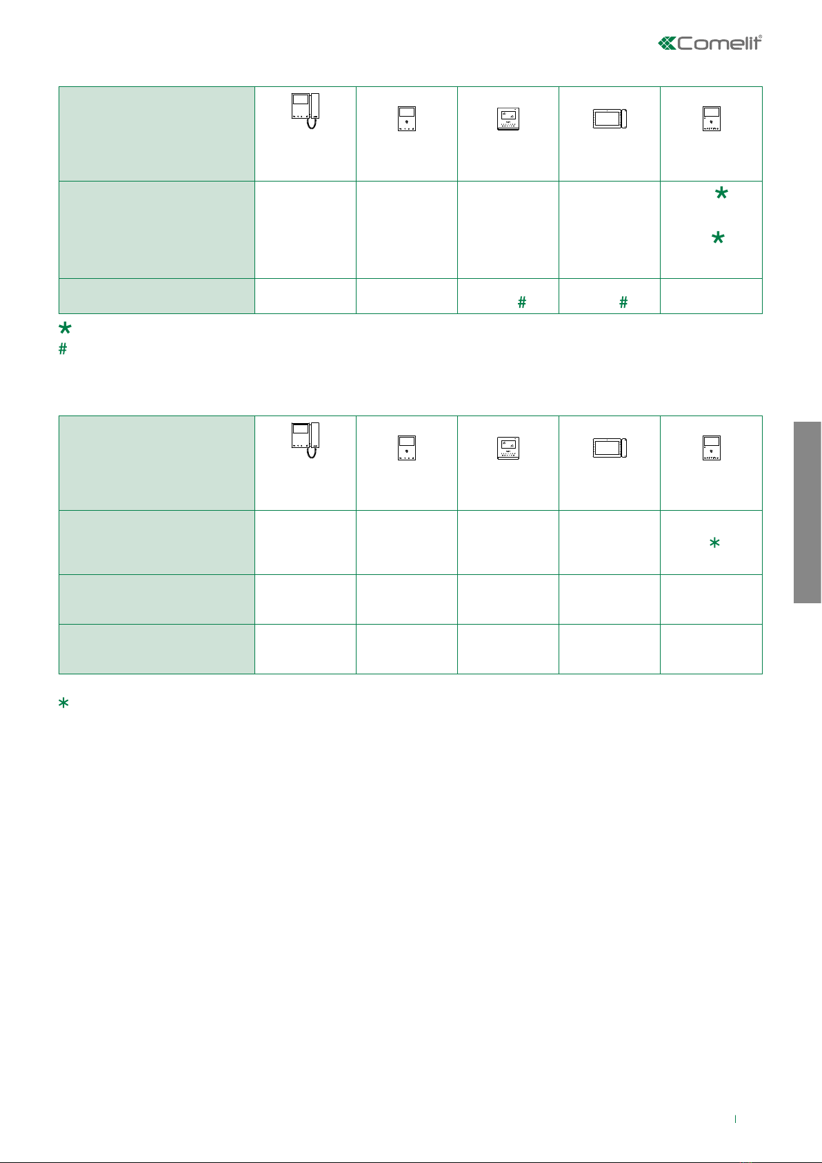
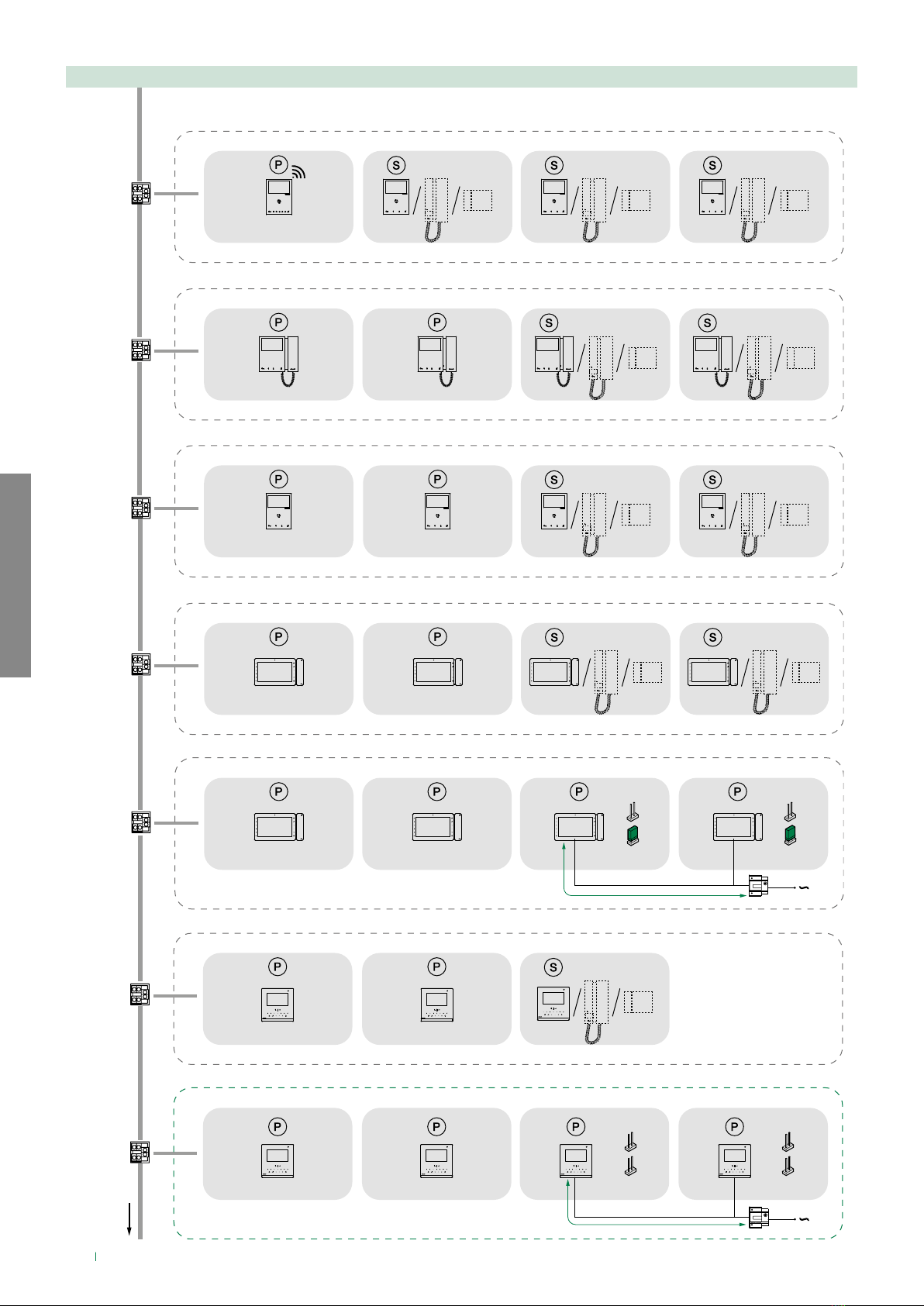
Maximum system expansion...................................................................7
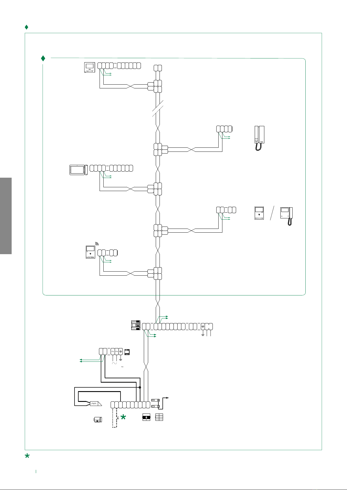
Maximum expansion per apartment.......................................................7
Example of maximum expansion per apartment................................8
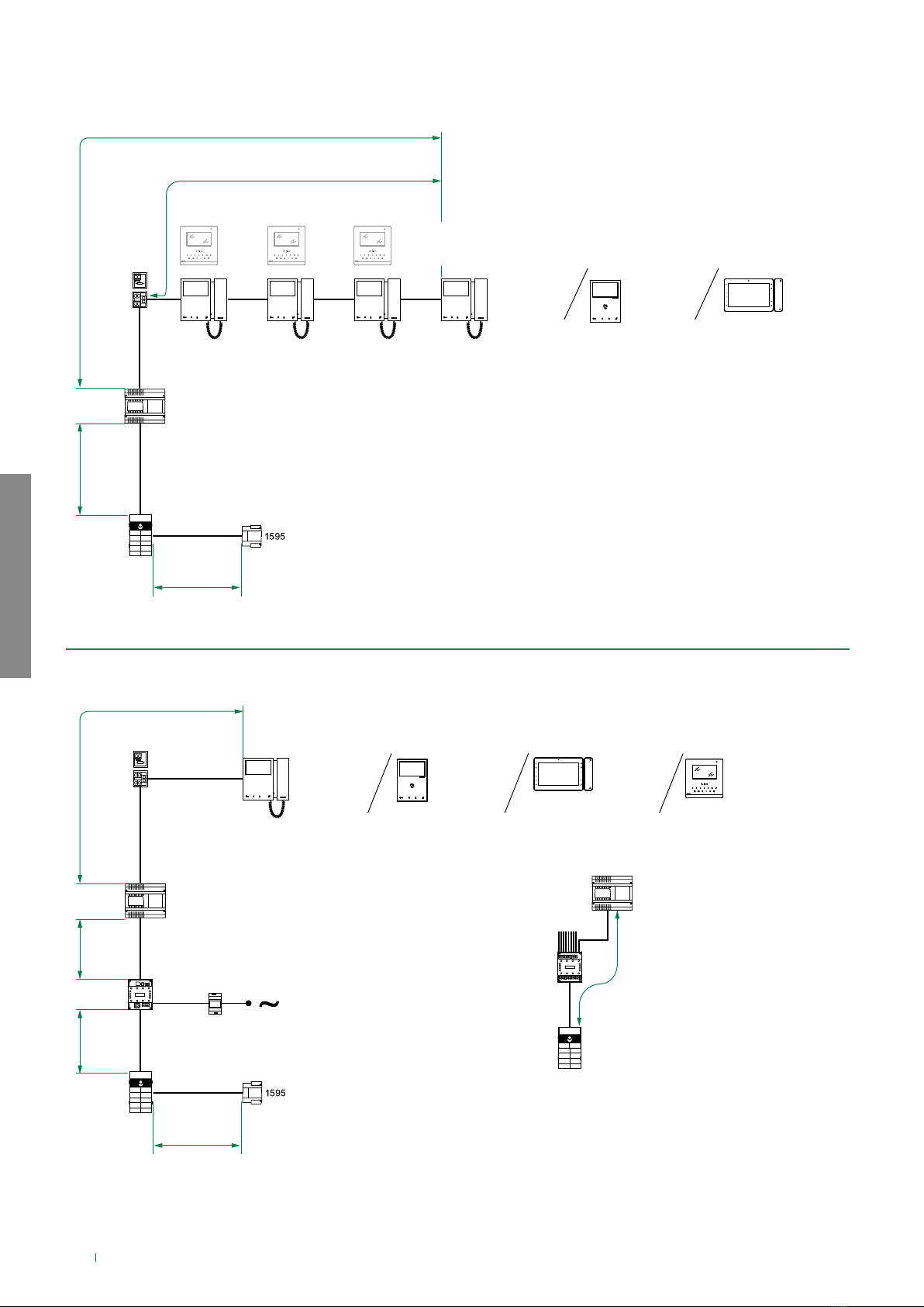
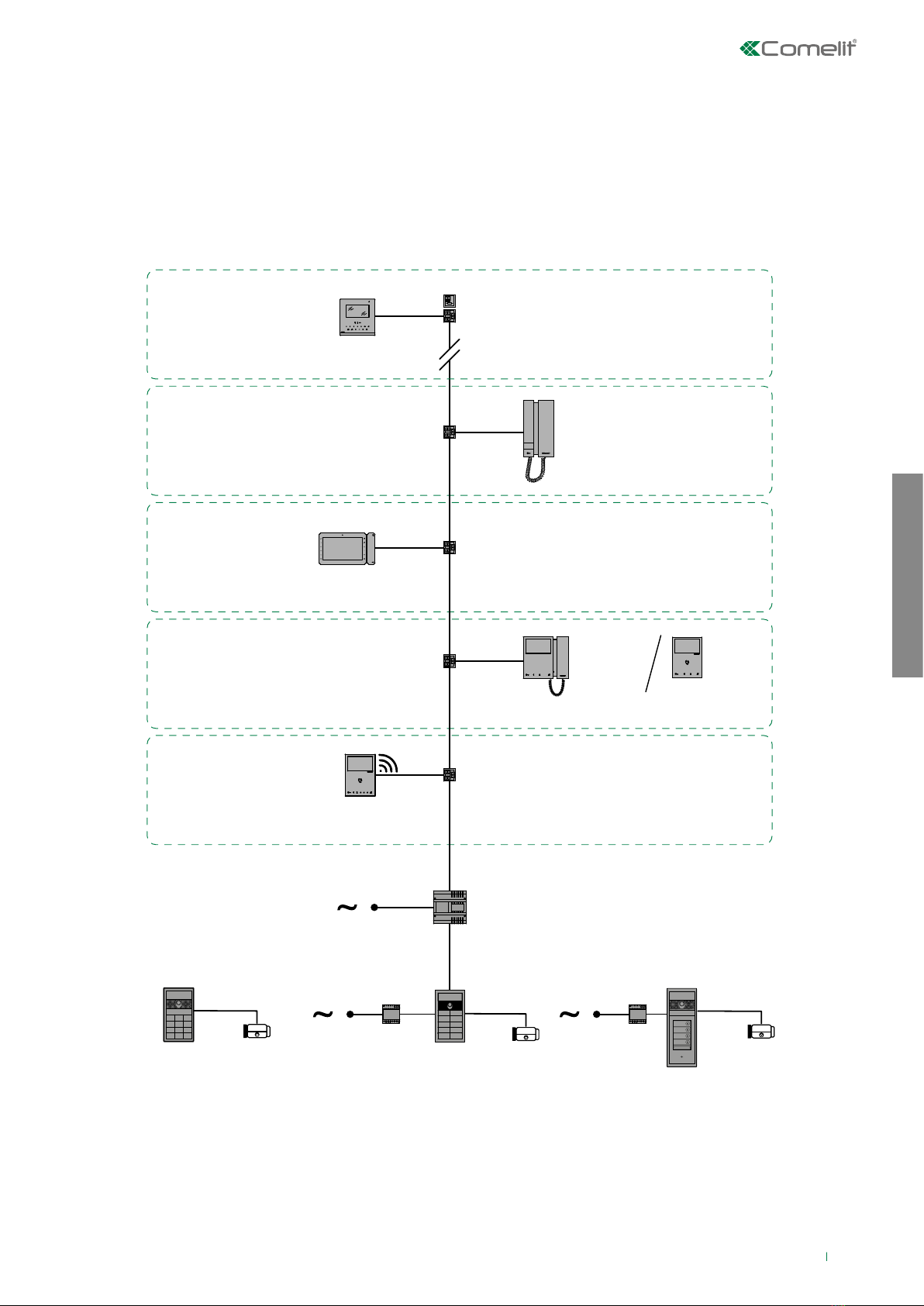
Wiring diagrams............................................................................... 9
System with a single riser .......................................................................9
Digital Entrance Panel Variant with Touch-screen module Art. UT927011
Digital Entrance Panel Variant with number keypad module Art.
UT9279M .................................................................................................11
Apartment block video entry phone system with 1 to 4 risers with 2
entrance panels......................................................................................12
Apartment block video entry phone system with more than 4 risers13
System with 1 main video entrance panel (max 9 secondary video
units)........................................................................................................14
Cascade connection for Art. 4834/9.....................................................16
Connection of amplifier Art. 4833C ......................................................17
Cascade connection with several door entry monitors or door-entry
phones (up to 25 per branch from Art. 4888C) ....................................18
Video entry system with 1 main entrance and porter switchboard ..19
Video entry system with 2 main entrances and porter switchboard 20
Video entry system with 1 main entrance, 3 secondary video units
and porter switchboard .........................................................................22
Video entry system with 2 main entrances, 3 secondary audio units
and porter switchboard .........................................................................24
Simplebus TOP video entry phone system with 1 main entrance,
4 secondary entrances and the corresponding secondary porter
switchboards ..........................................................................................26
Simplebus TOP video entry phone system with 2 main entrances, 4
secondary entrances and main porter switchboard...........................28
Simplebus TOP video entry phone system with 2 main entrances, 1
main porter switchboard, 2 secondary entrances and corresponding
porter switchboards...............................................................................30
Simplebus TOP video entry phone system with 1 main entrance, 4
secondary entrances and 2 main porter switchboards in SERIES....32
Simplebus TOP video entry phone system with 1 main entrance, 3
secondary entrances and 2 main porter switchboards in PARALLEL34
Switching devices in TOP1 mode, branched KIT 8461/8451, external
unit in TOP mode....................................................................................36
Switching devices in STANDARD mode, branched KIT 8461/8451....38
Switching devices in STANDARD mode and KIT 8461/8451 in cascade
connection ..............................................................................................40
Switching devices in TOP1 mode and KIT 8461/8451 in cascade
connection, with external unit in TOP mode........................................41
Addition of remote camera module Art. 1409......................................42
Addition of remote camera module Art. 1259C...................................43
System with remote camera module Art. 1259C in generic actuator
mode and porter switchboard ..............................................................44
Table of contents

SIMPLEBUS2 AUDIO-VIDEO
4
System functions
4888C
H
1214/2C
1216
6721W
6721W/BM
+6710
6601W
6601W/BM
(MAX 3)
6601W
6601W/BM
4833C
4888C
1214/2C
1216
6721W
6721W/BM
+6710
B
A
F
C
D
A
F
4888C
4834/9 E
6701W
6701W/8
6701W/BM
+6710
6801W
6801W/BM
6801W
6801W/BM
1200
UT1020
UT1020
UT1020
6701W
6701W/8
6701W/BM
+6710

SIMPLEBUS2 AUDIO-VIDEO
5
A MAX B MAX C MAX D MAX E MAX F MAX
G MAX
(see
page
8)
H MAX Art.1216
Comelit Art.4577/4579
1 mm²
(Ø 1.2 mm AWG 17)
200 m
(650 feet)
200 m
(650 feet)
200 m
(650 feet)
200 m
(650 feet)
150 m
(490 feet)
50 m
(165 feet)
50 m
(165 feet)
100 m
(330 feet)
2
1
UTP5 cat. 5 0.2 mm²
(Ø 0.5 mm AWG 24) 80 m
(260 feet)
150 m
(490 feet)
150 m
(490 feet)
150 m
(490 feet)
100 m
(330 feet)
60 m
(195 feet)
2
1
0.28 mm²
(Ø 0.6 mm AWG 23) 100 m
(330 feet)
150 m
(490 feet)
150 m
(490 feet)
150 m
(490 feet)
100 m
(330 feet)
5 m
(15 feet)
10 m
(30 feet)
60 m
(195 feet)
2
1
0.5 mm²
(Ø 0.8 mm AWG 20) 120 m
(395 feet)
100 m
(330 feet)
100 m
(330 feet)
100 m
(330 feet)
80 m
(260 feet)
25 m
(85 feet)
25 m
(82 feet)
60 m
(195 feet)
2
1
1 mm²
(Ø 1.2 mm AWG 17) 120 m
(395 feet)
150 m
(490 feet)
150 m
(490 feet)
150 m
(490 feet)
80 m
(260 feet)
50 m
(165 feet)
50 m
(165 feet)
60 m
(195 feet)
2
1
1 mm²
(Ø 1.2 mm AWG 17)
120 m
(395 feet)
80 m
(260 feet)
80 m
(260 feet)
80 m
(260 feet)
50 m
(165 feet)
50 m
(165 feet)
50 m
(165 feet)
40 m
(130 feet)
2
1
1.5 mm²
(Ø 1.4 mm AWG 15) 150 m
(490 feet)
100 m
(330 feet)
100 m
(330 feet)
100 m
(330 feet)
80 m
(260 feet)
75 m
(245 feet)
100 m
(330 feet)
60 m
(195 feet)
2
1
2.5 mm²
(Ø 1.8 mm AWG 13) 150 m
(490 feet)
100 m
(330 feet)
100 m
(330 feet)
100 m
(330 feet)
80 m
(260 feet)
100 m
(330 feet)
150 m
(490 feet)
60 m
(195 feet)
Operating distances
B
A
F
H
1214/2C
1595
1216
6741W
6741W/BM + 6710
3 DOOR ENTRY MONITORS / ART. 1229A MAX
4888C
UT1020
S3
DIP 1
Compatible secondary door entry monitors: 6701W (/BM), 6701W/8, 6721W (/BM), 6801W (/BM), 6601W (/BM)

SIMPLEBUS2 AUDIO-VIDEO
6
A MAX B MAX C MAX
NORMAL GAIN HIGH GAIN
Comelit Art.4577/4579
1 mm²
(Ø 1.2 mm AWG 17)
600 m
(1965 feet)
200 m
(655 feet)
300 m
(985 feet)
600 m
(1965 feet)
Comelit Art. 4576/4578
0.5 mm²
(Ø 0.8 mm AWG 20)
300 m
(985 feet)
200 m
(655 feet)
300 m
(985 feet)
600 m
(1965 feet)
UTP5 cat. 5 0.2 mm²
(Ø 0.5 mm AWG 24) 150 m
(495 feet)
150 m
(495 feet)
200 m
(655 feet)
300 m
(985 feet)
0.28 mm²
(Ø 0.6 mm AWG 23) 200 m
(655 feet)
150 m
(495 feet)
200 m
(655 feet)
300 m
(985 feet)
0.5 mm²
(Ø 0.8 mm AWG 20) 300 m
(985 feet)
100 m
(325 feet)
200 m
(655 feet)
300 m
(985 feet)
1 mm²
(Ø 1.2 mm AWG 17) 600 m
(1965 feet)
150 m
(495 feet)
200 m
(655 feet)
300 m
(985 feet)
1 mm²
(Ø 1.2 mm AWG 17)
600 m
(1965 feet)
80 m
(260 feet)
100 m
(325 feet)
150 m
(495 feet)
1.5 mm²
(Ø 1.4 mm AWG 15) 700 m
(2295 feet)
100 m
(325 feet)
200 m
(655 feet)
300 m
(985 feet)
Distances with video concentrator-amplifier Art. 4933
4933
4833C
4888C
B
A
C
1200
4888C
C
C
UT1020
For greater distances, please contact Comelit Group S.p.A. for information on using the data amplifier Art. 1236, to be
installed before Art. 4933.

SIMPLEBUS2 AUDIO-VIDEO
7
Maximum system expansion
Devices
6701W(/BM)
6701W/8
6721W(/BM) 6601W(/BM) 6801W(/BM) 6741W(/BM)
Maximum number of door
entry monitors that can be
powered from art. 4888C
100 100 100 100
100
(4888C with IR
≥053)
50
(4888C with IR
≥021 ≤052 )
Call repetition devices that can
be used 1229A 1229A 1229A
1229
1229A
1229 1229A
Devices
6701W(/BM)
6701W/8
6721W(/BM) 6601W(/BM) 6801W(/BM) 6741W(BM)
Maximum number of internal
units (including call repetition
devices) with the same user
code
44341
Maximum number of main
door entry monitors powered
from the riser
22221
Maximum number of main
door entry monitors that can
be powered from Art. 1212/B
/ / 1 2 /
For further information, see the manual for Art. 6741W
For installation information and limits, consult the relative manual
Maximum expansion per apartment
A single 6741W (/BM) door entry monitor can be installed for each user code; this will also be the only main door entry
monitor.
Up to 3 secondary door entry monitors can also be added (6701W (/BM), 6701W/8, 6721W (/BM), 6801W (/BM)
, 6601W (/
BM)).

SIMPLEBUS2 AUDIO-VIDEO
8
Example of maximum expansion per apartment
1214/2C
1214/2C
APARTMENT 6: max 4 internal units including 2 main internal units Art. 6701W 6701W/8
Art. 6741W
Art. 6801W
Art. 6721W
Art. 6801W
Art. 6601W
Art. 6601W
1214/2C
1214/2C
APARTMENT 4: max 4 internal units including 2 main internal units
APARTMENT 3: max 4 internal units including 2 main internal units + 2 main internal units powered separately
APARTMENT 5: max 4 internal units including 2 main internal units
1214/2C
1214/2C
APARTMENT 2: max 3 internal units including 2 main internal units
APARTMENT 1: max 4 internal units including 2 main internal units + 2 main internal units powered separately
4888C
CV1
CV2
CV1
CV2
1214/2C
APARTMENT 7: max 4 internal units including 1 main internal unit
6741W 6721W 6721W 6721W
A single 6741W (/BM) door entry monitor can be installed for each user code; this will also be the only main door entry monitor.
G
CV1
CV2
CV1
CV2
G

SIMPLEBUS2 AUDIO-VIDEO
9
4888C
1595
6721W
6741W
6701W
6701W/8
1214/2C
6801W
1214/2C
Apartment 1
1214/2C
Apartment 2
Apartment 3
Apartment 4
1216
6601W
1214/2C
Apartment n
1595
1214/2C
2738W
2738W/A
UT1020
UT9270
UT9279M
Wiring diagrams
System with a single riser

L
OUT
L
IN
L
IN
L
OUT
1214/2C
22-28 Vdc
L
OUT
L
IN
L
IN
L
OUT
1214/2C
LM
LM
C
F
P
LL
C
F
P
12
1 2 3 4 5 6
6701W
6701W/8
6701W/BM
+6710
22-28 Vdc
L
OUT
L
IN
L
IN
L
OUT
1214/2C
S
+
S
-
C
F
P
L L
C
F
P
1
-
+
2
IN
1 2
IN
6601W/
6601W/BM
22-28 Vdc
L
OUT
L
IN
L
IN
L
OUT
1214/2C
LM
LM
C
F
P
LL
C
F
P
12
6721W
6721W/BM
+6710
6741W
6741W/BM
+6710
IN
21
IN
2
+
-
1
P
F
C
LL
P
F
C
-
S
+
S
6601W/
6601W/BM
22-28 Vdc
22-28 Vdc
L
OUT
L
IN
L
IN
L
OUT
1214/2C
LM
LM
L L
C
F
P
C
F
P
2738W
2738W/A
LL
1216
LM
LM
LM
LM
E
T
R
GND
SE NO NC
C
O
M
LL
+
VV
-
~
+
-
4888C
1
L
IN
L
IN
L
4
L
3
L
2
L
1
L
3
L
2
L
4
L
230V
~ ~
26-28 Vdc
22-28 Vdc
UT1020 UT9200
120-230 V
-
+
1595
33 Vdc
SIMPLEBUS2 AUDIO-VIDEO
10
20 m MAX. Local door-opener button.
VIDEO ENTRY SYSTEM RISER

4888C
E
T
R
GND
SE NO NC
C
O
M
LL
+
VV
-
UT1020
UT9270
120-230 V
-
+
1595
SIMPLEBUS2 AUDIO-VIDEO
11
20 m MAX. Local door-opener button.
Digital Entrance Panel Variant with Touch-screen module Art. UT9270
Digital Entrance Panel Variant with number keypad module Art. UT9279M
4888C
UT9279M
E
T
R
GND
SE NO NC
C
O
M
LL
+
VV
-
UT1020
120-230 V
-
+
1595

SIMPLEBUS2 AUDIO-VIDEO
12
Apartment block video entry phone system with 1 to 4 risers with 2 entrance panels
4888C
1224A
6601W
2738W
2738W/A
6801W
6721W
6701W
6701W/8
6741W
1595
UT1020
1595
UT1020
P
L
P
L
S
L
S
L
M
L
M
L
+
~~
-
1224A
~~
230V
L
4
L
2
L
3
L
1
L
2
L
3
L
4
L
IN
L
IN
L
1
4888C
432
1
-
+
~
E
T
R
GND
SE NO NC
C
O
M
LL
+
VV
-
UT1020 UT9200
120-230 V
-
+
1595
E
T
R
GND
SE NO NC
C
O
M
LL
+
VV
-
UT1020 UT9200
120-230 V
-
+
1595
ON
MIN
1 2 3 4 6 75 8
ON
MAX
1 2 3 4 6 75 8
Video entry system riser (see: “VIDEO ENTRY SYSTEM RISER”)
20 m MAX. Local door-opener button.

SIMPLEBUS2 AUDIO-VIDEO
13
Apartment block video entry phone system with more than 4 risers
4834/9
4
L
4
L
1
L
1
L
IN
L
IN
L
3
L
3
L
2
L
2
LL
5
L
5
L
6
L
6
L
7
L
7
L
8
L
89
L
9
L
~
+
-
2
1 1
3 4
4888C
1
L
IN
L
IN
L
4
L
3
L
2
L
1
L
3
L
2
L
4
L
230V
~ ~ ~~
230V
L
4
L
2
L
3
L
1
L
2
L
3
L
4
L
IN
L
IN
L
1
4888C
432
-
+
~
E
T
R
GND
SE NO NC
C
O
M
LL
+
VV
-
UT1020 UT9200
120-230 V
-
+
1595
Video entry system riser (see: “VIDEO ENTRY SYSTEM RISER”)
20 m MAX. Local door-opener button.
Only cut o the resistor for the output used.
4888C
4834/9
4888C
6701W
6701W/8
6601W
2738W
2738W/A
6741W
6801W
6701W
6701W/8
6601W
2738W
2738W/A
6721W
6801W
1595
UT1020

SIMPLEBUS2 AUDIO-VIDEO
14
System with 1 main video entrance panel (max 9 secondary video units)
4888C
1224A
4888C
1224A
4834/9
6701W
6701W/8
6601W
2738W
2738W/A
6721W
6801W
6701W
6701W/8
6601W
2738W
2738W/A
6801W
6741W
1595
UT1020
1595
UT1020
1595
UT1020

SIMPLEBUS2 AUDIO-VIDEO
15
3 4
L
2
L
2
L
3
L
3
L
IN
L
IN
L
1
L
1
L
4
L
4
L
5
L
5
L
6
L
6
L
7
L
7
L
8
L
8
L
9
L
9
4834/9
65 87 9
P
L
P
L
S
L
S
L
M
L
M
L
+
~~
-
1224A1224A
-
~
~
+
L
M
L
M
L
S
L
S
L
P
L
P+
-
4888C
~
1
L
IN
L
IN
L
4
L
3
L
2
L
1
L
3
L
2
L
4
L
230V
~ ~~~
230V
L
4
L
2
L
3
L
1
L
2
L
3
L
4
L
IN
L
IN
L
1
~
4888C
-
+
E
T
R
GND SE NO NC
C
O
M
LL
+
VV
-
UT1020 UT9200
120-230 V
-
+
1595
E
T
R
GND SE NO NC
C
O
M
LL
+
VV
-
UT1020 UT9200
120-230 V
-
+
1595
E
T
R
GND SE NO NC
C
O
M
LL
+
VV
-
UT1020 UT9200
120-230 V
-
+
1595
Video entry system riser (see: “VIDEO ENTRY SYSTEM RISER”)
20 m MAX. Local door-opener button.
Only cut o the resistor for the output used.

SIMPLEBUS2 AUDIO-VIDEO
16
Cascade connection for Art. 4834/9
4834/9
4834/9
4833C
1200
6701W
6701W/8
6601W
2738W
2738W/A
6721W
6801W
6701W
6701W/8
6601W
2738W
2738W/A
6801W
4834/9
4833C
1200
6701W
6701W/8
6601W
2738W
2738W/A
6721W
6801W
4888C 4888C
4888C
6741W
1595
UT1020

SIMPLEBUS2 AUDIO-VIDEO
17
Connection of amplifier Art. 4833C
1200
12V~
230V~
-
~
+
~
OUT
L
OUT
L
IN
L
IN
L
4833C
FROM THE
EXTHERNAL UNIT
RISER
LINE
4834/9
4834/9
IN
L
IN
L
4
L
4
L
1
L
1
L
IN
L
IN
L
3
L
3
L
2
L
2
L
1200
12V~
230V~
-
~
+
~
OUT
L
OUT
L
IN
L
IN
L
4833C
L
5
L
5
L
6
L
6
L
7
L
7
L
8
L
8
L
9
L
9 9
L
9
L
8
L
8
L
7
L
7
L
6
L
6
L
5
L
5
LL
2
L
2
L
3
L
3
L
1
L
1
L
4
L
4
4
L
4
L
1
L
1
L
3
L
3
L
2
L
2
L L
5
L
5
L
6
L
6
L
7
L
7
L
8
L
8
L
9
L
9
4833C
L
IN
L
IN
L
OUT
L
OUT
~
+
~
-
230V~
12V~
1200
L
IN
L
IN
4834/9
123456
131211
87 9
10
4834/9
IN
L
IN
L
1200
12V~
230V~
-
~
+
~
OUT
L
OUT
L
IN
L
IN
L
4833C
9
L
9
L
8
L
8
L
7
L
7
L
6
L
6
L
5
L
5
LL
2
L
2
L
3
L
3
L
1
L
1
L
4
L
4
14 15 16 17 201918
25 26 2724232221
Video entry system riser (see: “VIDEO ENTRY SYSTEM RISER”)
Only cut o the resistor for the output used.

SIMPLEBUS2 AUDIO-VIDEO
18
LM
LM
OUT
L
IN
L
IN
L
1214/2C
OUT
L
LM
LM
OUT
L
IN
L
IN
L
1214/2C
MAX 100
MAX 25MAX 25 MAX 25
LM
LM
OUT
L
IN
L
IN
L
1214/2C
OUT
L
LL
1216
LL
1216
OUT
L
LL
1216
~~
230V
L
4
L
2
L
3
L
1
L
2
L
3
L
4
L
IN
L
IN
L
1
~
4888C
-
+
IN
21
IN
2
+
-
1
P
F
C
LL
P
F
C
-
S
+
S
6601W/
6601W/BM
CV5
L L
C
F
P
C
F
P
2738W
2738W/A
6801W/
S
+
S
-
C
F
P
L L
C
F
P
1
-
+2IN
1 2
IN
6801W/BM
IN
21
IN
2
+
-
1
P
F
C
LL
P
F
C
-
S
+
S
6601W/
6601W/BM
C
F
P
LL
C
F
P
12
6701W
6701W/8
L L
C
F
P
C
F
P
2738W
2738W/A
6750W
6721W
6721W/BM
C
F
P
LL
C
F
P
12
6801W/
S
+
S
-
C
F
P
L L
C
F
P
1
-
+2IN
1 2
IN
6801W/BM
C
F
P
LL
C
F
P
12
1 2 3 4 5 6
CV5
CV5
CV5 CV5
CV5
Cascade connection with several door entry monitors or door-entry phones (up to 25 per
branch from Art. 4888C)
In the case of connection in cascade, the MAX number of door entry monitors/door-entry phones that can be connected for
each riser branch of the Mixer-power supply Art. 4888C is 25. Each door-entry phone Art. 2738W, 2738/A and Art. 6750W
must be preceded by an Art. 1214/2C. For the distances permitted between the furthest door entry monitor/door-entry phone
and the Mixer-power supply Art. 4888C according to the cables, please refer to the table “Operating distances”column A.
4888C
6701W
6701W/8
1216
6601W
6801W
1214/2C
2738W
2738W/A
1216
6601W
1214/2C
2738W
2738W/A
6701W
6701W/8
1216
6601W
1214/2C
2738W
2738W/A
1216
1214/2C
6750W
6721W
6801W
MAX 25 MAX 25 MAX 25 MAX 25
1595
UT1020

SIMPLEBUS2 AUDIO-VIDEO
19
Video entry system with 1 main entrance and porter switchboard
4888C
1998VC
1195
6701W
6701W/8
6601W
6721W
6801W
6741W
1595
UT1020
~
+
-
4888C
1
L
IN
L
IN
L
4
L
3
L
2
L
1
L
3
L
2
L
4
L
230V
~ ~
NO C
D
N
G
1195
4
2
0
0
3
2
02
1
X
R
X
T
T
U
O
T
U
O
2
LP
H
C
H
C
M
L
M
L
0
~
24
~
1
LP
1998VC
E
T
R
GND
SE NO NC
C
O
M
LL
+
VV
-
UT1020 UT9200
120-230 V
-
+
1595
Video entry system riser (see: “VIDEO ENTRY SYSTEM RISER”)
20 m MAX. Local door-opener button.

SIMPLEBUS2 AUDIO-VIDEO
20
Video entry system with 2 main entrances and porter switchboard
4888C
1998VC
1195
1224A 1200
6601W
6801W
6701W
6701W/8
6721W
6741W
1595
UT1010
1595
UT1020
Other manuals for Simplebus2 Mini 2738W/A
3
This manual suits for next models
1
Table of contents
Other Comelit Security System manuals