Comelit Secur HUB User manual

EN
TECHNICAL
MANUAL
Secur HUB Installation and programming manual
Passion.Technology.Design.

2
Contents
Contents........................................................................................... 2
Hardware layout .............................................................................. 3
Control panel installation................................................................ 3
Removing the bracket..............................................................................3
LAN module installation ..........................................................................4
2G / 3G Module installation.....................................................................4
Changing brackets...................................................................................4
Choosing a proper mounting location ...................................................5
Connecting / replacing the battery.........................................................5
Installing the wall-mounted brackets.....................................................6
Installing the desk base...........................................................................6
The front panel................................................................................. 8
First power-up ................................................................................. 8
Installer menu access ..................................................................... 9
Installation Wizard........................................................................... 9
GSM/3G settings ......................................................................................9
Connect to Wi-Fi? ..................................................................................10
Connect to LAN? ....................................................................................11
Set time/date? ........................................................................................11
Entry/exit time? ......................................................................................12
Add RF zones? .......................................................................................13
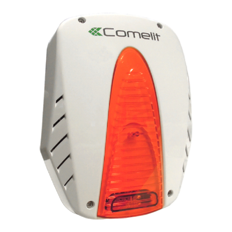
Add RF sirens? .......................................................................................14
Add users?..............................................................................................15
Add phonebook? ....................................................................................16
Connect APP? ........................................................................................16
Full menu ........................................................................................ 17
Service............................................................................................ 17
Time & date.............................................................................................17
Event Log ...............................................................................................17
Cloud.Inst. name ....................................................................................17
Mask Tamper ..........................................................................................19
Default Setting........................................................................................19
Match devices ........................................................................................19
Find RF device........................................................................................20
Forced settings.......................................................................................21
Languages ..............................................................................................21
Technical reset .......................................................................................21
Firmware version....................................................................................21
Firmware update ....................................................................................21
Manufact. code.......................................................................................21
Disable install? .......................................................................................21
Timers............................................................................................. 22
Entry Time...............................................................................................22
Exit Time .................................................................................................22
Siren Timer..............................................................................................23
Confirmed Alarm Timer .........................................................................23
Time program .........................................................................................24
Holiday groups..................................................................................24
Time programs..................................................................................24
Assign time program.........................................................................25
Time program composition example ................................................26
Self arming time................................................................................26
Extra time no.....................................................................................26
Ex.time duration................................................................................26
Auto arming type ..............................................................................26
Profiles & codes............................................................................. 28
User Profiles ...........................................................................................28
Select profile .....................................................................................28
Installer Code .........................................................................................28
Installer 1 ..........................................................................................28
Installer 2 ..........................................................................................29
Devices........................................................................................... 29
RF Zones.................................................................................................29
Wireless Zone Programming.............................................................29
Rf seq.prog .......................................................................................30
Rf single prg......................................................................................30
Edit zones .........................................................................................34
Zone Setting .....................................................................................34
Wired zones ............................................................................................35
Select zone .......................................................................................35
Keypads ..................................................................................................35
Edit keypads .....................................................................................35
RF sirens .................................................................................................38
RF siren acq......................................................................................38
Edit devices ......................................................................................40
Device settings .................................................................................40
Wired Outputs.........................................................................................40
Select output ....................................................................................40
CCTV devices .........................................................................................40
New CCTV device.............................................................................40
Edit CCTV device..............................................................................40
Areas............................................................................................... 41
Number of areas.....................................................................................41
Area description .....................................................................................41
Select area ........................................................................................41
Area assignment ....................................................................................41
Select Area/Zone ..............................................................................41
Area logic ................................................................................................41
Communications ........................................................................... 42
Phonebook & ARC .................................................................................42
Select zone .......................................................................................42
Event report set......................................................................................43
Messages recording ..............................................................................44
Audio options .........................................................................................45
Event Reporting opt...............................................................................46
Comm.Settings.......................................................................................48
System Options ............................................................................. 49
Arm/Disarm opt......................................................................................49
Arming programs ...................................................................................50
Supervision time.....................................................................................51
Jam.Control ............................................................................................51
Green LED...............................................................................................51
Technical reset .......................................................................................52
Macro ......................................................................................................52
Hardw. settings ......................................................................................53
False code...............................................................................................54
Alarm restore..........................................................................................54
Alarm mem.reset....................................................................................54
Save log-in/out .......................................................................................54
Menu timeout..........................................................................................55
FW download opt. ..................................................................................55
Walk test option .....................................................................................56
Chime time..............................................................................................56
Warnings

3
Hardware layout
Control panel installation
Removing the bracket
21
2
3
14
5
8
7
6
10 11
9
1. LCD/CAP-SENSE front panel
2. Microphone
3. Micro USB connector
4. Battery
5. Battery connector
6. Speaker
7. 2G/3G module connector
8. Tamper switch
9. Ethernet RJ45 connector
10. Wired I/O terminal block
11. A/C mains terminal block

4
LAN module installation
2G / 3G Module installation
21
21 3
21
Changing brackets

5
Choosing a proper mounting location
Connecting / replacing the battery
The following factors should be taken into account when choosing a proper mounting location for the control panel.
Functional factors:
• A wireless network is established when the control panel is up and running: avoid mounting the control panel close to RF
noise sources such as large electrical appliances or air-conditioners.
• The control panel should be located centrally in relation to its wireless peripherals.
• Avoid close proximity with large metal objects or surfaces.
• Radiofrequency propagation is negatively aected by the presence of metal-based construction materials; consider
minimising these kinds of obstacles.
• Depending on the communication channels that you intend to use, the control panel should be mounted in such a way as
to oer good GSM or WiFi signal strength.
• The availability of mains and Ethernet connections should be considered.
Security factors:
• The control panel must be mounted in such a way that accessing it while it is armed will trigger at least one detection zone.
• Install the control panel in a location that cannot be seen from outside the monitored premises.
• Keep out of reach of children, to prevent unintended operation.
Usability factors
• The mounting height of the control panel should be between 1.2 m and 1.8 m.
• Avoid installing the control panel behind doors or other obstacles that may cause delays in operating it.
Once the battery is replaced the control panel must be immediately reconnected to the bracket, so that it can boot up using
the main power supply and not only the battery.
Observe local regulations for proper battery disposal.

6
Installing the wall-mounted brackets
Installing the desk base
21 3
2A1A 3A
21 3
54 6

7

SYSTEM BOOTING...
LANGUAGES
ITALIANO
1
2
34
5 6 7
Enter wizard?
No:x Ok:↵
8
The front panel
1. 16x2 character LCD display.
2. LED indicators: green, yellow, red.
3. Alphanumeric keypad.
4. Arming / disarming buttons.
5. Back/undo/delete button.
6. Enter/confirm button.
7. Navigation pad / menu button.
• Green LED: indicates that the system is armed (steady) or is disarming (flashing).
• Yellow LED: indicates a malfunction (steady) or isolated / bypassed zones (flashing).
• Red LED: indicates an alarm / tamper in progress (steady) or a logged alarm (flashing).
First power-up
During the first power-up, the panel will ask you to select a language.
Use the Down/Up arrow on the navigation pad to select the desired language and confirm by pressing the Enter button.

16:25 15/11/2019
****..
Installer menu
Wizard menu
GSM/3G settings
< ok:↵>
SIM number:
38745378
9
Installation Wizard
The installation Wizard is a step-by-step guide that can be used to set up the main features required to get a basic system up
and running. Every step of the procedure allows setting of a specific parameter.
GSM/3G settings
The first step of the installation wizard is setting up the GSM/3G module (if installed).
fEnter the menu by pressing the Enter/Confirm button.
fEnter the SIM number using the alphanumeric keypad and confirm when finished by pressing the Enter/Confirm button.
Installer menu access
The installer menu contains all the system configuration options.
To access the Installer menu:
fEnter the installer code, default 001961, using the alphanumeric keypad and press the down arrow.
If the SIM card is locked you will be asked to enter the PIN. If the SIM card is already unlocked, the “PIN number - unlocked”
message will be displayed.

APN:
Connect to WIFI?
< ok:↵>
Select network:
Searching ...
Password:
123456
10
fEnter the APN of the service provider; this will be used to enable data trac for the SIM card.
fConfirm by pressing the Enter/Confirm button.
Connect to Wi-Fi?
The second step of the installation wizard is connecting to a Wi-Fi network.
fEnter the menu by pressing the Enter/Confirm button.
The panel will scan the area for all available SSIDs.
fSelect the desired network using the navigation pad and confirm with the Enter/Confirm button.
If the network is password-protected the panel will request it.
fEnter the password with the alphanumeric keypad and confirm with the Enter/Confirm button.
It is optionally possible to let the control panel generate its own access point (with own SSID and password). Scroll all Wi-Fi
networks and select as the last item the “STAY ACC. POINT” option. This function allows the connection of WiFi IP cameras
directly to the control panel.

Connect to LAN?
< ok:↵>
Select option: ↓↑
Use DHCP
Select option: ↓↑
Use DHCP
Ip address:
192.168.1.2
Set time/date?
< ok:↵>
Set time:
16:46:36
11
Connect to LAN?
The third step of the installation wizard is connecting to a LAN network.
fEnter the menu by pressing the Enter/Confirm button.
There are two options available for setting the panel IP address
• Use DHCP (the panel will receive an IP address automatically)
• Set manually
If the manual option is selected, use the alphanumeric keypad to enter the IP address and confirm by pressing the Enter/
Confirm button.
Set time/date?
The fourth step of the installation wizard is setting the system time and date.
fEnter the menu by pressing the Enter/Confirm button.
fUse the navigation pad and the alphanumeric keypad to set the correct time.
fConfirm by pressing the Enter/Confirm button.
If the control panel is already connected to the Internet (using Wi-Fi, Ethernet or a GPRS/3G module), the time will be updated
automatically via an NTP server.

Set date:
26:06:2018
Entry/exit time?
< ok:↵>
Entry time:
030 sec
Exit time:
030 sec
12
fUse the navigation pad and the alphanumeric keypad to set the correct date.
fConfirm by pressing the Enter/Confirm button.
Entry/exit time?
The fifth step of the installation wizard is used to set the entry and exit delays.
The Entry Time is the time lapse available on opening the Entry/Exit zone, allowing you to disarm the system before an alarm is
triggered.
The Exit Time is the time lapse available on opening and closing the Entry/Exit zone after arming the system, to avoid triggering
an alarm or generating an exit fault.
To set a zone as Entry/Exit refer to the chapter “Add RF zones?” on page 13.
fEnter the menu by pressing the Enter/Confirm button.
fSet the entry time using the alphanumeric keypad and confirm by pressing the Enter/Confirm button.

Add RF zones?
< ok:↵>
Zone 01 ↓↑
Enroll?
Zone 01 ↓↑
1:edit 2: delete
Zone 01
Enrolling now...
Zone 01
Acquired!
Output 01
Retry?
Description:
Zone 01
Type:
Alarm
13
Add RF zones?
The sixth step of the installation wizard is used to enrol RF detectors.
1. Enter the menu by pressing the Enter/Confirm button.
2. Choose the zone to be enrolled using the navigation keypad and confirm by pressing the Enter/Confirm button.
»If the zone has been assigned to a device, the menu “1:Edit 2:Delete” is available.
• Alarm: This zone type will cause an Intruder alarm if it is
activated when the system/area is armed.
• Entry/Exit: The zone can be activated during exit mode
without causing a ‘Fault’. Once the system/area is armed,
zone activation will start the ‘Entry 1 Delay’ timer for the
selected area. This zone type can only trigger an alarm if
the exit time has elapsed.
• Access: This zone type will allow the user to trigger the
detector without causing a ‘Fault’ during the exit time or
an Intruder alarm during the entry time; however, the zone
will generate an immediate Intruder alarm if activated at
any other time.
»If the zone is free, the control panel waits for an acquiring signal from devices; refer to the device technical manual for the
correct procedure.
»If the device is correctly enrolled the panel displays the “Acquired!” message; if not, the “Retry?” message is shown.
3. Enter the device name using the alphanumeric keypad and confirm by pressing the Enter/Confirm button.
4. Assign a zone type using the navigation keypad and confirm by pressing the Enter/Confirm button.

Area:
A1
Partition:
P1
Select option: ↓↑
Add more zones
Select option: ↓↑
Next wizard step
Add RF sirens?
< ok:↵>
Output 01 ↓↑
Enroll?
Output 01 ↓↑
1:edit 2:delete
Output 01
Enrolling now...
Output 01
Acquired!
Output 01
Retry?
14
5. Choose the area to which the zone will be assigned using the navigation keypad and confirm by pressing the Enter/Confirm
button.
6. Choose the partition (P1, P2 or P1+P2) to which the zone will be assigned using the navigation keypad and confirm by
pressing the Enter/Confirm button.
7. Select the next step using the navigation keypad and confirm by pressing the Enter/Confirm button.
Add RF sirens?
The seventh step of the installation wizard is used to enrol RF sirens.
1. Enter the menu by pressing the Enter/Confirm button.
2. Select the output to be enrolled using the navigation keypad and confirm by pressing the Enter/Confirm button.
»If the output has been assigned to a device, the menu “1:Edit 2:Delete” is available.
»If the zone is free, the control panel waits for an acquiring signal from devices; refer to the device technical manual for the
correct procedure.
»If the device is correctly enrolled the panel displays the “Acquired!” message; if not, the “Retry?” message is shown.

Description:
Output 01
Add users?
< ok:↵>
User 01 code: ↓↑
______
User 01: ↓↑
1:reset 2:delete
User 01 code: ↓↑
******
Confirm code:
****** Operation done!
Description:
User 01
Select option: ↓↑
Assign remote
15
3. Enter the device name using the alphanumeric keypad and confirm by pressing the Enter/Confirm button.
Add users?
The eighth step of the installation wizard is adding users and remotes.
fEnter the menu by pressing the Enter/Confirm button.
fChoose the user to be added using the navigation keypad and confirm by pressing the Enter/Confirm button.
If the user has been registered the menu “1:Reset 2:Delete” is available.
fEnter the code for the user using the alphanumeric keypad and confirm by pressing the Enter/Confirm button.
fConfirm the code using the alphanumeric keypad and confirm by pressing the Enter/Confirm button.
fEnter the name for the user using the alphanumeric keypad and confirm by pressing the Enter/Confirm button.
It is possible to assign a remote to the user just created.
fSelect the option using the navigation keypad and confirm by pressing the Enter/Confirm button.

Remote 01
Enrolling now...
Remote 01
Acquired!
Add phonebook?
< ok:↵>
Connect APP?
< ok:↵>
Control panel ID
123456789
16
fPress any button on the remote
Add phonebook?
The ninth step of the installation wizard allows the addition of contacts for event reporting.
fEnter the menu by pressing the Enter/Confirm button.
Each phonebook contact may have more than one field, such as phone number, email or APP ID. For phone numbers it is
possible to select which kind of report will be used: SMS, Voice or both. Subsequent configuration steps are proposed for each
contact. Contacts can be browsed with Up/Dn arrows for editing existing. Filling in data fields such as phone number or email
will automatically enable that contact to receive default event reports.
Connect APP?
The tenth step of the installation wizard is used to register Comelit App accounts to the control panel.
1. Enter the menu by pressing the Enter/Confirm button.
»The panel displays an ID number that should be entered when requested by the App during the creation of a new system.
2. Follow the steps on the App to complete the procedure.

16:25 15/11/2019
***..
Installer menu
Service
Service
Event log
Event log
Alarms memory
17
Full menu
When this option is enabled the whole menu is visible to the installer. When disabled, only the most important menu items are
displayed in the installer menu tree. Deepest parameter configurations are hidden to allow a better browsing of the menus.
Service
Time & date
This menu item allows the setting of all parameters relating to time and date:
• Set time: the time must be set in HH:MM format
• Date format: the date format is available in two patterns, DD:MM:YYYY or MM:DD:YYYY
• Date: Date must be set according to date format
• Time zone: Select between UTC-12 and UTC+14
• Daylight saving time: Europe/USA/Disable. This function allows setting of the control panel to automatically follow the
daylight saving time changes according to Europe or USA standards. The option can be also disabled.
• Ntp server: Enable/disable options and addresses for up to four NTP servers are provided.
Event Log
The control panel memory can contain up to 1024 events. New events are recorded in the memory as event #000. Event 1023
becomes event 1024 and thus is deleted from the memory.
• Events memory
Event log command will show the entire events list.
• Alarms memory
Alarms memory will show only the alarm events for the last arming period. This log is cleared at the next arming action.
Possible choices are:
To consult the log:
fEnter the installer code, default 001961, using the alphanumeric keypad and press the down arrow.
fNavigate to the Service menu using the navigation pad and enter the menu by pressing the Enter/Confirm button.
fNavigate to the Event log menu using the navigation pad and enter the menu by pressing the Enter/Confirm button.
Cloud.Inst. name
In this menu you are requested to enter a name, that will be stored in the cloud, to identify the system. The name is used to
target the specific installation during remote programming via SecurHUB manager software.

R:Alarm:Burglary
03:36:26 02/01
5A: Back Window
Ground floor ID:0001
ID:0001
ID:0001
5A: Back Window
Ground floor
5A: Back Window
Ground floor
R:Alarm:Burglary
03:36:26 02/01
R:Alarm:Burglary
03:36:26 02/01
(EVENTQUAL)(EVENT)
(TIME)(DATE)
[WHERE]
(EVENTID)(RXACK)
(WHO)
(AREA)
18
Event type (activation or restore), Event description and Event timestamp are displayed first.
fFor additional information, press the right arrow on the navigation pad; after doing so all other data will be displayed.
fTo scroll through the log, use the up and down arrows on the navigation pad. See below for the navigation pattern inside
the Event log.
»Each event has applicable attributes:
EventQual R: for restore
Empty: for activations
Event Description of the event
Time Time at which the event occurred
Date Date on which the event occurred
Who User or device that generated the event
Area Area in which the event occurred
Where Device on which the event was generated
EventID 4-figure ID number of the event
RxAck RX for events that have been acknowledged by at least one recipient
NRX for events that have not been acknowledged
During event log consultation it is possible to filter the event list according to the main categories using buttons 0 to 7.
Button Filter name Event groups to be displayed
0 Reset filters All events
1 Alarms Alarms
2 Tampers Tampers
3 Bypass / Unbypass Zone bypass / Unbypass
4 Battery / Mains faults Device battery faults, CP battery faults, CP Mains fault
5 Other faults System faults
6 Arm / Disarm Total arm, Partial arm, Disarm, Forced arm
7 System operation System operations, technical programming

Service
Mask tamper
Service
Default setting
Service
Match devices
Paired: 00 of 15
↓ For pending ID
19
Mask Tamper
After enabling this option it is possible to remove the control unit from the bracket and then exit the installer menu without
notifying a 24H tamper alarm. It is thus possible to use the control unit from the user menu by “masking” the tamper signal. As
soon as the control unit is closed again, the tamper control is reactivated and upon the next reopening the tamper alarm will be
notified.
Default Setting
This menu item allows the installer to restore the control panel to its default factory settings.
• Load default: On selecting this function the system prompts the selection of one of two sets:
◊ Free default: This default set is not EN50131 compliant.
- Clear access codes? If confirmed, this function resets the user and installer access codes to their factory default. If not
confirmed, the default settings will preserve all user codes from being deleted.
- Clear RF devices? If confirmed, this function deletes all paired RF devices. If not confirmed, all RF devices will be
preserved from being deleted while uploading the default settings.
◊ EN Standards: This setting will be available soon.
- Clear access codes? If confirmed, this function resets the user and installer access codes to their factory default. If not
confirmed, the default settings will preserve all user codes from being deleted.
- Clear RF devices? If confirmed, this function deletes all paired RF devices.
• Restore access codes: This function resets the user and installer access codes to their factory default.
• Clear all RF devices: This function deletes all paired RF devices. If not confirmed, all RF devices will be preserved from
being deleted while uploading the default settings.
• HW default option: This menu item allows you to select which default set will be restored when a hardware default is
applied.
• Reboot: This function reboots the control panel.
Match devices
This menu is used to activate the RF devices that have been enrolled on the control panel only using the device ID code.
Accessing this menu allows you to browse the list of the devices that are still pending (only ID registered).
fNavigate to the Match devices menu using the navigation pad and enter the menu by pressing the Enter/Confirm button.
When inside this menu, the panel is “receptive” to enrolling signals coming from devices that are in the “pending” list. When a
valid signal coming from a valid device ID arrives at the panel, the device is stored and the index of paired devices increases.
When all pending devices have been paired, the message “Operation done!” is displayed.

Service
Find RF device
Find RF device
Find RF zones
Select zone
Zone 01
Zone 01
Found!
20
Find RF device
This menu allows you to launch an individual “Find” command to the registered RF devices by turning on their LEDs to identify
them on the premises. After a device has been found, its LEDs will blink for a few seconds and the message “Found!” is
displayed.
To find a device:
fNavigate to the Find RF device menu using the navigation pad and enter the menu by pressing the Enter/Confirm button.
fNavigate to the type of device to find using the navigation pad and enter the menu by pressing the Enter/Confirm button.
• Find RF zones
Allows you to select the RF zones to be found.
• Find RF outputs
Allows you to select the RF outputs or sirens to be
found.
• Find RF remotes
Allows you to select the RF remotes to be found.
• Find RF keypads
Allows you to select the RF keypads to be found.
fNavigate to the zone / output / remote / keypad to be found using the navigation pad and enter the menu by pressing the
Enter/Confirm button.
This manual suits for next models
2
Table of contents
Other Comelit Security System manuals
Popular Security System manuals by other brands

Night Owl
Night Owl NONB-44500 instruction manual

Fright Ideas
Fright Ideas Director Connect quick start guide

Olympia
Olympia Protect 6 Series operating manual

Supco
Supco TA44 user guide

urmet domus
urmet domus 1068 Installation and programming manual

VOX electronics
VOX electronics CA 160 installation instructions