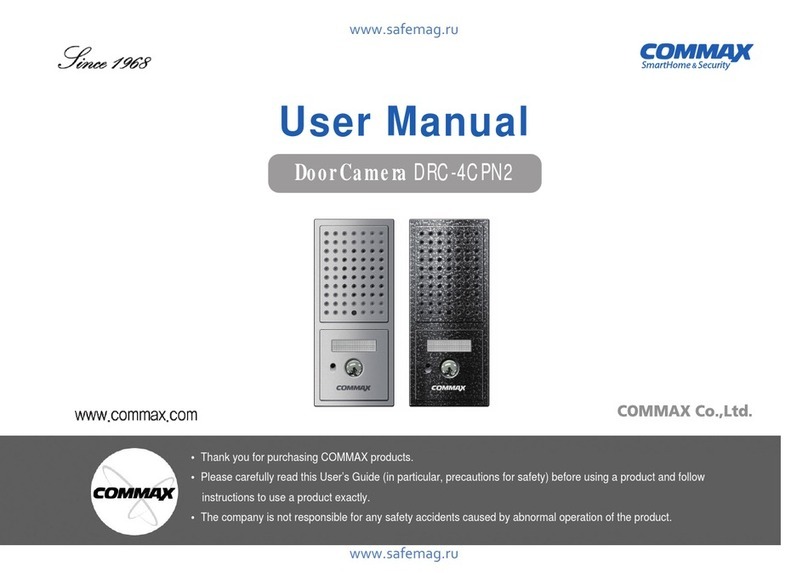
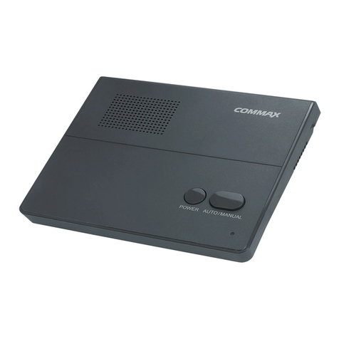
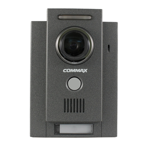
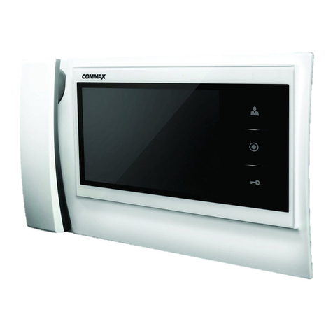
Commax APV-4RH User manual

Video DoorPhone
Model No. DPV-4RH/APV-4RH
.in.ua
www.commax.in.ua

- 1 -
Introdu
c
tion
W ARNIN G
To preventfire or sho
c
k hazard, do not
expose the unitto rain or moisture.
INFORMATIO N
This equipment generates and uses radio frequency
energy and if not installed and used properly; that is,
in stric t ac c ordanc e with the manufac turer’s
instructions, may c ause interference to radio and
television rec eption. It has been type tested and
found to comply with the limitations for a C lass B
c omputing devic e in ac c ordanc e with the
spec ific ations in S ubpart J of Part 15 of the FC C
Rules, which are designed to provide reasonable
protec tion against such interference in a residential
installation. However, there is no guarantee that
interference will not occur in a particular installation.
If this equipment does cause interference to radio or
television reception, which c an be determined by
turning the equipment off and on, the user is
encouraged to try to correct the interference by one
or more of the following measures:
- Reorientor relocatethereceiving antenna.
-Increasetheseparation between theequipmentand
receiver.
- C onnecttheequipmentto an outletofa circuit
dif f erentfr omth a tto wh ich thereceiver is
connected.
- Consultthedealer or on experienced r adio / TV
technicion for help.
This symbol is intended to alert the
user to the presence of uninsulated
“ dangerousvoltage” within the
product’s enclosure that may be of
sufficient magnitude to constitute a
risk of electric shock to persons.
This symbol is intended to alert the
user to the presenc e of important
operating and maintenanc e
(servic ing) instruc tions in the
literature accompanying the unit.
CAUTIO N : TO REDUCETHERISK O FELECTRIC
SHOCK, DO N OTREM OVECOVER(ORBACK). N O
USER-SERVICEABLEP A RTSINSIDE. REFER
SERVICING TO QUALIFIED SERVICEPERSO N NEL.
CAUTIO N
RISK OFELECTRICSHOCK
DO N OTOPEN
TO PREVENTELECTRICSHOCK, DO N OT
USETHISP OLARIZED ACPLU G WITH
AN EXTENSIO N CORD, RECEPTACLEOR
OTHEROUTLET, U N LESS THEBLADES
CA N BEFULLY INSERTED TO PREVENT
BLADEEXPOSURE.

- 2 -
ImportantSafety Instru
c
tions
1. Re a d Ins t r u
c
tio ns- A ll the safety and
operating instructions should be read before the
product is operated.
2. Retain Instru
c
tions- The safety and operating
instruc tions should be retained for future
reference.
3. Heed W arnings- All warnings on the product
and in the operating instruc tions should be
adhered to.
4. Follow Instru
c
tions- All operating and use
instructions should be followed.
5. Cleaning - Unplug this product from the wall
outlet before cleaning. Do not use liquid cleaners
or aerosol. Use a damp cloth for cleaning.
6. Atta
c
hments- Do not use attachments not
recommended by the product manufacturer, as
they may cause hazards.
7. W a te r a n d M o is tu r e - Do not use this
product near water - for example, near a bath
tub, wash bowl, kitchen sink, laundry tub, in a
wet basement, near a swimming pool, and the
like.
8. A
cc
essories- Do not place this product on an
unstable cart, stand, tripod bracket, or table. The
product may fail, causing serious injury to a child
or adult, and serious damage to the product. Use
only with a cart, stand, tripod, bracket, or table
recommended by the manufacturer, or sold with
the product. Any mounting of the product should
follow the manufacturer’s instructions, and should
use a mounting ac cessory rec ommended by the
manufacturer.
9. A produc t and c art
c ombination should be
moved with care. Q uick
stops, excessive force, and
uneven surfac es may
c ause the produc t and
cart combination to overturn.
10. V e n tila tio n - S lots and openings in the
c abinet are provided for ventilation and to
ensure reliable operation of the product.
They protect it from overheating, and these
openings must not be blocked or c overed. The
openings should never be blocked by placing the
product on a bed, sofa, rug, or other similar
surface. This product should not be placed in a
built-in installation suc h as a bookc ase or rac k
unless proper ventilation is provided, or the
manufacturer’s instructions have been adhered to.
11. Pow er Sou r
c
es- This produc t should be
operated only from the type of power source
indicated on the marking label. If you are not
sure of the type of power supply in your home,
consult your product dealer or local power
company. For products intended for operation
from battery power or other sources, refer to the
operating instructions.
12. Grounding or Polarization - This product
may be equipped with a polarized alternating-
current line plug (a plug having one blade wider
than the other). This plug will fit into the power
outlet only one way. This is a safety feature. If
you are unable to insert the plug fully into the
outlet, try reversing the plug. If the plug still
cannot be inserted, contact your electrician to
replace your obsolete outlet. Do not defeat the
safety purpose of the polarized plug.
- 3 -
ImportantSafety Instru
c
tions
13. Po w er -Ca r d Prote
c
tio n - Power- supply
cords should be routed so that they are not likely
to be walked on or pinched by items plac ed
upon or against them paying particular attention
to cords at plugs, convenience receptacles, and
the point where they exit from the product.
14. Prote
c
tive Atta
c
hmentPlug - The product
is equipped with on attac hment plug having
overload protection. This is a safety feature. See
instruc tion Manual for replac ement of, or
resetting the protective device. If replacement of
the plug is required, be sure the servic e
technician has uses a replacement plug specified
by the manufacturer that has the same overload
protection as the original plug.
15. O utdoor A nten na G ro un d in g - If an
outside antenna or cable system is connected to
the product, be sure the antenna or cable system
is grounded so as to provide some protection
against voltage surges and built- up static
charges. A rticle 810 of the N ational Electrical
C ode, AN S I/N FPA 70, provides information
with regard to proper grounding of the mast
and supporting structure, grounding of the lead-
in wire to an antenna discharge unit, size of
grounding conductors, loc ation of antenna-
disc harge unit, c onnec tion to grounding
electrodes, and requirements for the grounding
electrode (Refer to the figure on page 5 ).
16. Lig htnin g - For added protec tion of this
product during a lightning storm, or when it is
left unattended and unused for long periods of
time, unplug it from the wall outlet and
disconnect the antenna or cable system. This will
prevent damage to the product due to lightning
and power-line surges.
17. Po wer Lin es- A n outside antenna system
should not be located in the vicinity of overhead
power lines or other elec tric light or power
circuits, or where it can fall into such power
lines or circuits.
W hen installing on outside antenna system,
extreme c are should be taken to keep from
touching such power lines or circuits as contact
with them might be fatal.
18. Overloading - Do not overload wall outlets,
extension c ords, or integral c onvenienc e
receptacles, as this can result in a risk of fire or
electric shock.
19. O bje
c
tan d Liq uid Entr y - N ever push
objects of any kind into this product through
openings as they may touch dangerous voltage
points or short-out parts that could result in a
fire or elec tric shock. N ever spill liquid of any
kind on the product.
20. Ser vi
c
ing - Do not attempt to servic e this
product yourself as opening or removing covers
my expose you to dangerous voltage or other
hazards. Refer all servicing to qualified service
personnel.
21. Damage Requiring Servi
c
e - Unplug this
product from the wall outlet and refer servicing
to qualified servic e personnel under the
following conditions.
A. W hen the power-supply c ord or plug is
damaged.
B. If liquid has been spilled, or objects have
fallen into the product.
C . If the product has been exposed to rain or
water.

- 4 -
D. If the product does not operate normally by
following the operating instruc tions. Adjust
only those controls that are c overed by the
operating instruc tions, as an improper
adjustment of other c ontrols may result in
damage and will often require extensive
work by a qualified technician to restore the
product to its normal operation.
E. If the product has been dropped or damaged
in any way.
F. W hen the product exhibits a distinct change
in performance - this indic ates a need or
service.
22. Rep la
c
ementPa rts - W hen replac ement
parts are required, be sure the servic e
technician has used replacement parts specified
by the manufac turer or have the same
c harac teristic s as the original part.
Unauthorized substitutions may result in fire,
electric shock or other hazards.
23. Sa fety Ch e
c
k - Upon c ompletion of any
service or repairs to this product, ask the service
technician to perform safety checks to determine
that the produc t is in proper operating
condition.
24. W all or Ceiling Mounting - The produc t
should be mounted to a wall or ceiling only as
recommended by the manufacturer.
25. Heat- The product should be situated away
from heat sourc es suc h as radiators, heat
resistors, or other products (including amplifiers)
that produce heat.
ImportantSafety Instru
c
tions

- 5 -
Table of Contents
Introduction ............................................................................................................................ 1
Important Safety Instructions ..................................................................................................... 2
Table of C ontents .................................................................................................................... 5
1. Features ............................................................................................................................5
2. Parts C hecklist and Functions................................................................................................6
3. Installation Instructions.........................................................................................................7
4. O peration ..........................................................................................................................8
5. W iring ...............................................................................................................................9
6. Parts List...........................................................................................................................10
7. Installation Precaution........................................................................................................10
8. Specifications....................................................................................................................11
1.Features
This product was designed with circuitry that allows trouble-free, long-lasting operation and a clean
picture. It is easily mountable on the wall without any modifications to the wall itself.
Easy installation
It is a wall-mountable design for easy installation.
Clear pi
c
ture
This product utilizes a flat C RT tube to provide you with a clear picture.
Crisp pi
c
ture
This product incorporates the latest technology to provide a crisp picture.

- 6 -
2. Parts Che
c
klist and Fun
c
tions
1 Monitor Screen 4”Flat B/W C RT
2 Microphone Sends voice to the camera.
3 Bell volume control C ontrols the volume of the ringtone.
4 Power switch C ontrols the power to the unit.
5 Brightness control C ontrols the brightness of the screen.
6 APV-4RH(G uardroom) Allows communication with the guardroom.
DPV-4RH(O pen) O pens the front gate if so equipped.
7 Priority C all Allows only the household’s voice to be heard
8 Monitor/Talk Displays the screen and initiates communication
9 LED light Power on: Yellow, Signal from camera or guardroom : Red
During a conversation : Red
10 Speaker Voice from the camera or guardroom is delivered
11 Individual(DPV models), guardroom(APV models) connection socket
12 Power cord insertion trenches
ሪ
Monitor(DPV-4RH)
ሪ
Camera(DRC-403N)
1 Front Panel
2 C amera protection window
3 C C D camera lens
4 Infrared LED : Allows for good visibility even when the lighting
conditions are less than adequate
5 Speaker Sound from the monitor is delivered
6 Page button pages the monitor to initiate communication
7 Screw hole cover
8
C amera Pivoting Lever
Allows the camera lens to pivot about for the
optimum angle
9 Monitor connection socket

- 7 -
3. Installation Instru
c
tions
ሪ
Monitor Installation
ሪ
Camera Installation
■
Installation Lo
c
ation
•
Avoid installing the c amera where it is
exposed to direct sunlight
•
The visitor’s image may not be clearly
visible if there are surrounding lighting
sources behind the visitor in which case,
separate lighting may be necessary.
■
Installation Lo
c
ation
Avoid installation in the following type of
environments :
•
In direct sunlight
•
High temperature, humidity areas
•
A reas where the unit is exposed to toxic
chemicals
•
Areas where a strong magnetic field is present
•
Areas where appliances such as a heater or
air conditioner is present
■
Monitor mounting height
The mounting height should be
approximately 5ft’(145cm) off the
ground

- 8 -
4. Operation
※
C all duration and monitor display time :
•W hen only the screen is displayed with no dialog : 30 sec.
•W hen dialog takes place : 1min. 30 sec.
※The maximum duration for a dialog between the monitor and
the guardroom station is 5 minutes at a time.
N ote : The lamp will turn
yellow once the call
has ended
1.
Visitor Call
2 .
Dialog with the guardroom (APV-4RH)
➔➔
a chime sounds
end the call
Visitor
presses
call button
on camera
the visitor’s
image
appears on
the monitor
➔
➔
the talk button is
pressed on the
monitor for
conversation
➔➔
Monitor of the
guardroom
➔
guardroom C all
dialog begins
➔➔
A visitor calls
from the front
gate
the door
opens
3.
Door release fun
c
tion(DPV-4RH)
➔
the outside image will be
visible on the screen for
30 seconds at a time.
4 .
To view the outside from the indoor monitor
to end the call
➔
end the dialog with
the guardroom
call from the
front gate
➔➔
Dialog with the
guardroom
the screen
image becomes
larger
➔
dialog with the visitor
the dialog with the
visitor ends
call from the
guardroom
➔➔
Dialog with
a visitor
a continuous
‘beep’
will be heard
➔
the screen
turns off
➔
dialog with the
guardroom begins
dialog is initiated

- 9 -
5. Wiring
■
W iring precautions
1. If high voltage cables are present in the vicinity, use a coaxial cable with metal outer casing.
2. If any external wiring is exposed, it may cause a short and become a cause of malfunction or fire.
3. W hen connecting the monitor and camera, make sure that the monitor power is off.(Turn on the
power after plugging the AC power cord into the outlet)

- 10 -
6. Parts list
7. Pre
c
aution during installations
DPV-4RH ORAPV-4RH)1
W all-mountable bracket 1
O wner’s manual, main unit 1
wall-mounting screws 4
connector(4P) 1
connector(2P) 1
camera(optional equipment) 1
ሪ
Monitor(DPV-4RH)
*
Do not install where excess dust or humidity is present
*C onnect the wires to the proper socket
*Attach the equipment securely
*Do not install the unit where it is exposed to constant sunlight or rain
*Be careful not to scratch the door camera lens cover
(A PV - 4R H )

- 11 -
8. Spe
c
ifi
c
ations
C onnection method 4 wires in polarity
Voltage requirements AC 100V~240V, 50/60Hz
Power consumption Standby mode : 2.5W , during operation : 15W
Monitor screen 4”B/W flat C RT monitor
C ommunication method Simultaneous type
C all tone Electronic chime/melodic tone(guardroom)
C alling distance 50m (ø0.65)
O perating temperature 0℃~+40℃(32℉~104℉)
Dimensions(mm) 211(W ) X 226(H) X 52(D)
Model: DPV-4RH / APV-4RH
C onnection method 4 wires in polarity
Voltage requirements DC 12V(supplied from the monitor)
Imaging Device 1/3”B/W C C D
Viewing Angle Horizontal : 68°
, Vertical : 55°
Adjustability Up : 29°
, Down : 26°
Minimum illumination 0 Lux (30cm in front of the camera)
O perating temperature -10℃~+40℃(14℉~104℉)
Dimensions(mm) 125(W ) X 182(H) X 46(D)
Model: DRC-403N

513-11, Sangdaewon-dong, Jungwon-gu,
Seongnam-si, G yeonggi-do, Korea
Int’lBusiness Dept. :
Tel.; +82-31-7393-540~550
Fax.; +82-31-745-2133
W eb site : www.commax.com
Printed In Korea
This manual suits for next models
1
Table of contents
Other Commax Intercom System manuals

Commax
Commax CDV-43K User manual

Commax
Commax CVD-40N User manual

Commax
Commax CMA-3L User manual

Commax
Commax DR-24ML User manual

Commax
Commax CAV-40NG User manual

Commax
Commax DRC-4M User manual

Commax
Commax CDV-40N User manual

Commax
Commax cav-35gn User manual

Commax
Commax CDV-50 User manual

Commax
Commax dpv-4be User manual

Commax
Commax DP-2T User manual

Commax
Commax DRC-nAC2 User manual

Commax
Commax DP-MHP User manual

Commax
Commax BRYCO DP-LA01 User manual

Commax
Commax DP-LA01M User manual

Commax
Commax PI-10LN User manual

Commax
Commax CDV-71BE/D User manual

Commax
Commax WDP-174LM User manual

Commax
Commax CMV-70M User manual

Commax
Commax DRC-4BG User manual