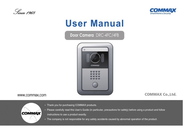
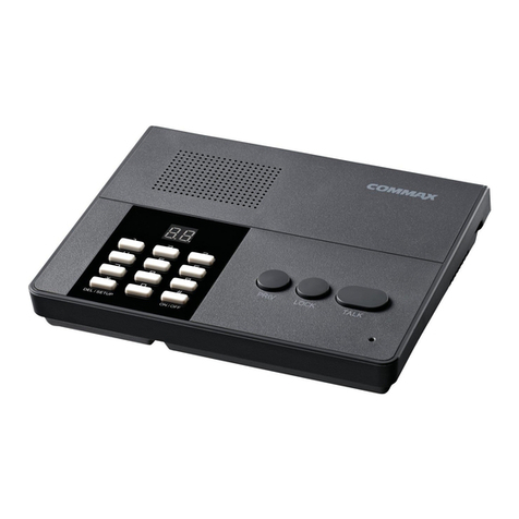
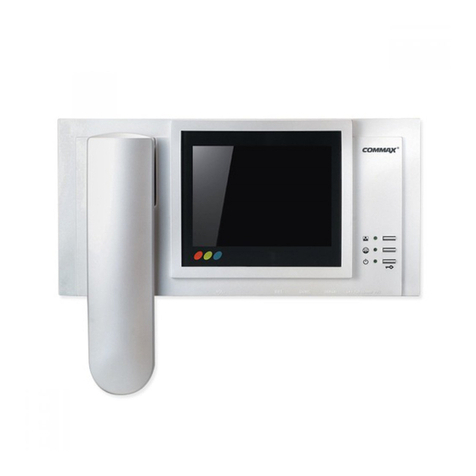
Commax CDS-481L User manual

- 1 -
Introduction
WARNING
To prevent fire or shock hazard, do not expose
the unit to rain or moisture.
INFORMATION
This equipment generates and uses radio frequency
energy and if not installed and used properly; that is,
in strict accordance with the manufacturer’s
instructions, may cause interference to radio and
television reception. It has been type tested and
found to comply with the limitations for a Class B
computing device in accordance with the
specifications in Subpart J of Part 15 of the FCC
Rules, which are designed to provide reasonable
protection against such interference in a residential
installation. However, there is no guarantee that
interference will not occur in a particular installation.
If this equipment does cause interference to radio or
television reception, which can be determined by
turning the equipment off and on, the user is
encouraged to try to correct the interference by one
or more of the following measures:
- Reorient or relocate the receiving antenna.
- Increase the separation between the equipment and
receiver.
- Connect the equipment to an outlet of a circuit
different from that to which the receiver is
connected.
- Consult the dealer or on experienced radio/TV
technicion for help.
This symbol is intended to alert the
user to the presence of uninsulated
“dangerous voltage” within the
product’s enclosure that may be of
sufficient magnitude to constitute a
risk of electric shock to persons.
This symbol is intended to alert the
user to the presence of important
operating and maintenance
(servicing) instructions in the
literature accompanying the unit.
CAUTION : TO REDUCE THE RISK OF ELECTRIC SHOCK, DO
NOT REMOVE COVER (OR BACK). NO USER-SERVICEABLE
PARTS INSIDE. REFER SERVICING TO QUALIFIED SERVICE
PERSONNEL.
CAUTION
RISK OF ELECTRIC SHOCK
DO NOT OPEN
TO PREVENT ELECTRIC SHOCK, DO NOT USE
THIS POLARIZED AC PLUG WITH AN
EXTENSION CORD, RECEPTACLE OR OTHER
OUTLET, UNLESS THE BLADES CAN BE FULLY
INSERTED TO PREVENT BLADE EXPOSURE.

- 2 -
Important Safety Instructions
1. Read Instructions - All the safety and operating
instructions should be read before the product is
operated.
2. Retain Instructions - The safety and operating
instructions should be retained for future
reference.
3. Heed Warnings - All warnings on the product
and in the operating instructions should be
adhered to.
4. Follow Instructions - All operating and use
instructions should be followed.
5. Cleaning - Unplug this product from the wall
outlet before cleaning. Do not use liquid cleaners
or aerosol. Use a damp cloth for cleaning.
6. Attachments - Do not use attachments not
recommended by the product manufacturer, as
they may cause hazards.
7. Water and Moisture - Do not use this product
near water - for example, near a bath tub, wash
bowl, kitchen sink, laundry tub, in a wet
basement, near a swimming pool, and the like.
8. Accessories - Do not place this product on an
unstable cart, stand, tripod bracket, or table. The
product may fail, causing serious injury to a child
or adult, and serious damage to the product. Use
only with a cart, stand, tripod, bracket, or table
recommended by the manufacturer, or sold with
the product. Any mounting of the product should
follow the manufacturer’s instructions, and should
use a mounting accessory recommended by the
manufacturer.
9. A product and cart
combination should be
moved with care. Quick
stops, excessive force, and
uneven surfaces may
cause the product and
cart combination to overturn.
10. Ventilation - Slots and openings in the cabinet
are provided for ventilation and to ensure
reliable operation of the product.
They protect it from overheating, and these
openings must not be blocked or covered. The
openings should never be blocked by placing the
product on a bed, sofa, rug, or other similar
surface. This product should not be placed in a
built-in installation such as a bookcase or rack
unless proper ventilation is provided, or the
manufacturer’s instructions have been adhered to.
11. Power Sources - This product should be
operated only from the type of power source
indicated on the marking label. If you are not
sure of the type of power supply in your home,
consult your product dealer or local power
company. For products intended for operation
from battery power or other sources, refer to the
operating instructions.
12. Grounding or Polarization - This product may
be equipped with a polarized alternating-
current line plug (a plug having one blade wider
than the other). This plug will fit into the power
outlet only one way. This is a safety feature. If
you are unable to insert the plug fully into the
outlet, try reversing the plug. If the plug still
cannot be inserted, contact your electrician to
replace your obsolete outlet. Do not defeat the
safety purpose of the polarized plug.

- 3 -
Important Safety Instructions
13. Power-Card Protection - Power-supply cords
should be routed so that they are not likely to be
walked on or pinched by items placed upon or
against them paying particular attention to
cords at plugs, convenience receptacles, and the
point where they exit from the product.
14. Protective Attachment Plug - The product is
equipped with on attachment plug having
overload protection. This is a safety feature. See
instruction Manual for replacement of, or
resetting the protective device. If replacement of
the plug is required, be sure the service
technician has uses a replacement plug specified
by the manufacturer that has the same overload
protection as the original plug.
15. Outdoor Antenna Grounding - If an outside
antenna or cable system is connected to the
product, be sure the antenna or cable system is
grounded so as to provide some protection
against voltage surges and built-up static
charges. Article 810 of the National Electrical
Code, ANSI/NFPA 70, provides information
with regard to proper grounding of the mast
and supporting structure, grounding of the lead-
in wire to an antenna discharge unit, size of
grounding conductors, location of antenna-
discharge unit, connection to grounding
electrodes, and requirements for the grounding
electrode (Refer to the figure on page 5 ).
16. Lightning - For added protection of this product
during a lightning storm, or when it is left
unattended and unused for long periods of time,
unplug it from the wall outlet and disconnect the
antenna or cable system. This will prevent
damage to the product due to lightning and
power-line surges.
17. Power Lines - An outside antenna system should
not be located in the vicinity of overhead power
lines or other electric light or power circuits, or
where it can fall into such power lines or
circuits.
When installing on outside antenna system,
extreme care should be taken to keep from
touching such power lines or circuits as contact
with them might be fatal.
18. Overloading - Do not overload wall outlets,
extension cords, or integral convenience
receptacles, as this can result in a risk of fire or
electric shock.
19. Object and Liquid Entry - Never push objects of
any kind into this product through openings as
they may touch dangerous voltage points or
short-out parts that could result in a fire or
electric shock. Never spill liquid of any kind on
the product.
20. Servicing - Do not attempt to service this product
yourself as opening or removing covers my
expose you to dangerous voltage or other
hazards. Refer all servicing to qualified service
personnel.
21. Damage Requiring Service - Unplug this
product from the wall outlet and refer servicing
to qualified service personnel under the
following conditions.
A. When the power-supply cord or plug is
damaged.
B. If liquid has been spilled, or objects have
fallen into the product.
C. If the product has been exposed to rain or
water.
- 4 -
D. If the product does not operate normally by
following the operating instructions. Adjust
only those controls that are covered by the
operating instructions, as an improper
adjustment of other controls may result in
damage and will often require extensive
work by a qualified technician to restore the
product to its normal operation.
E. If the product has been dropped or damaged
in any way.
F. When the product exhibits a distinct change
in performance - this indicates a need or
service.
22. Replacement Parts - When replacement parts
are required, be sure the service technician has
used replacement parts specified by the
manufacturer or have the same characteristics
as the original part. Unauthorized substitutions
may result in fire, electric shock or other
hazards.
23. Safety Check - Upon completion of any service
or repairs to this product, ask the service
technician to perform safety checks to determine
that the product is in proper operating
condition.
24. Wall or Ceiling Mounting - The product should
be mounted to a wall or ceiling only as
recommended by the manufacturer.
25. Heat - The product should be situated away
from heat sources such as radiators, heat
resistors, or other products (including amplifiers)
that produce heat.
Important Safety Instructions

- 5 -
Table of Contents
Introduction ............................................................................................................................ 1
Important Safety Instructions ..................................................................................................... 2
Table of Contents .................................................................................................................... 5
1. Greeting.......................................................................................................................... 6
2. Before Getting Started ..................................................................................................... 6
3. Overview
3-1. Overview ............................................................................................................... 7
3-2. Essentials................................................................................................................. 8
4. To Connect with Households
4-1. Being Paged by the Household............................................................................... 10
4-1-1. Request from the Household to Confirm the Last Household it has Connected to. 10
4-2. Paging the Household from the Guardhouse (Paging another Guardhouse)................. 11
5. To Connect a Household with another Household ............................................................. 12
6. Selecting and Answering Missed Pages........................................................................... 13
7. Connecting to the Main Entrance
7-1. To Connect to the Guardhouse from the Main Entrance............................................. 14
7-2. To Connect to the Main Entrance From the Guardhouse............................................ 15
8. Paging and Connecting to a Household using Registered Vehicle Numbers
(Parking Management System)........................................................................................ 16
9. Announcement.............................................................................................................. 17
10. Call Block................................................................................................................... 18
11. Away Mode Setting and Security Mode Extension from the Guardhouse .......................... 19
12. Emergencies within Households..................................................................................... 22
13. Delivery...................................................................................................................... 24
14. Confirming Household Conditions ................................................................................ 25
15. Adjusting Time........................................................................................................... 30
16. Advanced Feature (Please use only after understanding its handling to the full)
16-1. Registering Household Numbers........................................................................... 31
16-2 Registering Household Vehicles (Parking Management System)
16-2-1. Registering with Known Vehicle Number.................................................... 33
16-2-2. Registration by the Household through the Guardhouse ............................... 35
16-3. Checking Household Numbers using Vehicle Numbers........................................... 36
16-4. To Open or Close the Main Entrance
16-4-1. To Temporarily Release the Main Entrance ................................................. 37
16-4-2. To Open the Entrance for Indefinitely.......................................................... 39
16-4-3. To Close Main Entrances ........................................................................... 40
17. Guardhouse Interphone Program Confirmation and Modification..................................... 43
[Table 1] Guardhouse Interphone Program Number and Description................................ 47
18. Wiring Method .......................................................................................................... 49
19. Specifications.............................................................................................................. 64

- 6 -
1. Greeting
●
Thank you for purchasing a Commax product.
●
This state-of-the-art Guardhouse Interphone switchboard contains the parking management
system, individual household checking feature, and various other essential services in security.
Please read this user manual carefully and familiarize yourself with its contents before use.
●
Being a product that utilizes the common wiring method, adhering yourself to basic wiring
instructions when installing will surely prove this product as a convenient one.
2. Before Getting Started
●
Using 8-wire common wiring method between the Main Entrance interphone and the
Guardhouse interphone, this system supports 3 communication circuits, and each communication
circuit is a Balance Type that supports 2 wires.
●
Using 18-wire common wiring method between the Guardhouse interphone and the Guardhouse
interphone, this system supports 8 communication circuits, and each communication circuit is a
Balance Type that supports 2 wires.
●
The Guardhouse interphone and the Guardhouse interphone can support 8 extensions, where
16-wire common is added. (Extensions are only supported when CDS-481S has been installed)
●
Shorts or disconnection in wiring are factors of product malfunction. Please check them before
wiring
※
Remarks

- 7 -
3. Overview
3-1. Overview
Number Description Number Description
1. Time Adjustment Button
2. Household Selection Button
3. LCD
4. Enter Button
5. Away Button
6. Remote Control Button
7. Extension Button
8. Redial Button
9. Volume Adjustment
10. Key Pad
11. Call Block Button
12. Confirmation Button
13. Change Location Buttons (←,→)
14. Open
15. Emergency Page
16. Speed Dial Buttons
17. P.A. Button
18. Call Connection Button
19. Speakerphone
20. Call Button
21. Parking Management System
22. Emergency Lamp
23. Away Lamp
24. Call Lamp
25. Guardhouse Indicator Section
26. Household Indicator Section
27. Building Button
28. Outside Line Lamp
29. Internal Line Lamp
30. Delivery Button

- 8 -
3-2. Essentials
*Household Selection Button/Lamp: Used to select one of the Households indicated on the
Household Indicator Section.
*Time Adjustment Button/Lamp: Used to adjust time.
*Enter Button/Lamp: Used to execute the Guardhouse Interphone’s programs.\
*Confirmation Button/Lamp: Used to confirm changes made to data within the Guardhouse
Interphone’s programs.
*Call Block Button/Lamp: Forwards calls to other Guardhouses or Households. (Available only
when a forwarding number has been entered in Pr03)
* Away Registration Button/Lamp: Controls the Household Videophone’s Away feature from the
Guardhouse.
* Remote Control Button/Lam: Used to verify and adjust various information of the Household
Videophone.
* (
) Button/Lamp: Used to confirm or make changes to entered data.
* Extension Button/Lamp: Used to assign Multi Sub numbers to the Household Videophone and
in various other extension processes.
* Redial Button/Lamp: Pages the last number paged.
* Emergency Page/Lamp: Pages to connect to a Household with an emergency.
* Open Button/Lamp: Used to release the Main Entrance.
No. 1: OFF - cannot be connected to a computer.
: ON - can be connected to a computer.
: (Computer connection feature is optional)
No. 2: OFF - Household emergencies are received by all installed
Guardhouse Interphones.
: ON - Household emergencies are received only by the
corresponding Guardhouse.
ON
1 2
OFF
ON
1 2
ON
ON
1 2
OFF
ON
1 2
ON
Selection Switches

- 9 -
* Key Pad: Used to enter in numbers.
* Building Button: Used to distinguish buildings when
entering Household numbers.
* Call Button (#): Used to page after entering a
Household number.\
* P.A. Button/Lamp: Used for announcements among
Guardhouses
* Call Connect Button/Lamp: Used to connect a
Household to another Household or another
Guardhouse.
* Speakerphone Button/Lamp: Activates the
speakerphone.
* Guardhouse Indicator Section
* Household Indicator Section
* Speed Dial Buttons (1 to 8): Often dialed numbers.
* Line Indicators (LED) Red/Green: Indicates the status of each
outside line (1 to 16).
* Internal Line Indicator (LED): Indicates the status of each
internal line (1 to 3).
* Confirmation Button: Used when verifying a Household using
Vehicle Number.
* Vehicle Button: Used to page a Household using Vehicle
Number. (Two vehicles can be registered per household)
* Emergency Indicator (Blinks when an Emergency Page has
been made)
* Away Indicator (Blinks when an Emergency Page or Call has
been made from a Household in Away Mode)
* Page Indicator (Blinks with paging and other data
communication)
*The lamp will continuously blink when an error or short has
been detected along the Data Line.
*The following messages are indicated on the LCD:
Int Com Line Err : Internal Line Error
Ext Com Line Err : Outside Line Error

- 10 -
4. To Connect with Households
4-1. Being Paged by the Household
①
A paging signal will sound from the Guardhouse interphone when a Household has paged
the Guardhouse.
①
While staying connected with the Household,
②
Press the Extension button.
③
Press Outside Line 1 button. (Indicated while the Outside Line 1 button has been pressed)
④
The last Household connected to the Household on line is displayed on the LCD. Inform the
Household of its last connection.
4-1-1. Request from the Household to Confirm the Last Household it has Connected to
②
Pickup the Receiver to answer.
LCD
Call < 0101 - 0101
Pickup the Receiver to answer.
ex)From Building 101, Unit 101.
Connected to
the Household Press the
Extension button Press Call 1 The last household
connected to is
displayed.

- 11 -
4-2. Paging the Household from the Guardhouse (Paging another Guardhouse)
①
Pickup the receiver and enter the Building Number of the Household to connect to using
the Key Pad.
(To page another Guardhouse, enter in 9999)
②
Press the Building button (
✽
). (The number indicated on the LCD and the Guardhouse
Indicator Section moves to the Building location)
③
Enter the Household Number using the Key Pad. (To page another Guardhouse, enter the
Guardhouse Interphone’s Serial Number)
④
Press the Call button. (Ringing tone will sound)
⑤
Await a reply.
⑥
If a busy signal is heard, hang-up and page again after a few minutes.
Building button
Call button
Paging Tone will Sound
Ex) Unit 101
Ex) Unit 101

- 12 -
5. To Connect a Household with another Household
①
When a request to connect to another household has been made while connected to the
Household,
②
Press the Call Connection button. (The lamp will light up)
※
(Warning) Guardhouse calls cannot be forwarded.
③
Use the Key Pad to enter in the Household Building Number to connect to and press the
Building button.
⑤
Hang-up.
Building button
After Entering the
Household Building
Number
④
Use the Key Pad to enter in the Household Number to connect to and press the Page
button.(Ringing tone, lit up Call Connect lamp, and ‘Exchange OK’ indicated on the LCD)
Page button
LCD
Exchange OK....
Beep -
Beep
If wrong Building Number or Household Number has been entered, use the Correction (
-)
button to make changes.

- 13 -
6. Selecting and Answering Missed Pages
①
When a Household page has been made while the Guardhouse Interphone’s line was busy,
the Household Number where the page originated from and the Household Selection
Button/Lamp light up on the Household Indicator Section.
②
Press the Household Selection button after ending the initial call to connect with the second
Household.
<Note>
If the Household indicated on the Household Indicator Section is not selected within 30
seconds, that Household will no longer be indicated on the top portion of that section and
be replaced by the next Household in line.
“
When the Guardhouse is on a call with Unit 101
from Building 101
”
Ex)Being paged by Unit 303 from
Building 101
“After Ending the
Call Household
Select 1”
“Connecting to the
Following Household.
Ex) Being paged by Unit
303 from Building 101

- 14 -
7. Connecting to the Main Entrance
7-1. To Connect to the Guardhouse from the Main Entrance
①
A paging signal will sound when the Guardhouse has been paged from the Main Entrance.
(Main Entrance Number indicated on the LCD and the Guardhouse Indicator Section)
③
Pressing the Door Release button while connected to an entrance will open it.
LCD
Call < 0101 - 9901
A Paging Signal will Sound
ex)101동 1번째
공동현관에서
호출이 올 경우
The Main Entrance will Open
②
Pickup the receiver to answer.

- 15 -
7-2. To Connect to the Main Entrance From the Guardhouse
①
Pickup the receiver and press the number of the entrance to connect to.
②
Press the Page button.
③
Await for a reply.
Ex) To connect to the first
Main Entrance of
Building 101.
Page button
A Paging Signal will
Sound
Connecting
to the Main
Entrance
The Main Entrance will Open
④
Pressing the Door Release button while connected to an entrance will open it.

- 16 -
This feature is only available when Vehicle Numbers have been registered to each Household.
(Refer to the registration method in 16-2)
①
Pickup the receiver and enter the number of the vehicle registered in the Parking
Management System.(‘car> - ‘ will be displayed on the LCD)
8. Paging and Connecting to a Household using Registered Vehicle Numbers (Parking Management System)
To page a houshold using the above vehicle number: Pickup the receiver -
Press the Vehicle Button - Enter 32 - Press the Building button -- Enter 2580
- Press the Page button ? Wait for a reply
③
Await a reply.
Ex) Gyeonggi 32 Ga 2580
Vehicle Number
Region Number (1 to 2 digits)
Enter the
Region Number
(1 to 2 digits)
Enter the
Vehicle Number
(4-digits)
LCD
Car > -
②
Use the Key Pad to enter in the vehicle’s region number and press the Building button. Use
the Key Pad to enter in the vehicle’s 4-digit number and press the Page button.
Building button Page button

- 17 -
①
Pickup the receiver and enter the group number to announce to using the Key Pad.
9. Announcement
②
Press the P.A. button.
③
After the announcement indication sounds, make the announcement.
Start the Announcement
<Note>
(As for Announcement Groups, please refer to data recorded in Pr22 of the Guardhouse
interphone)
00 : All
⇒
Announcement is heard through all installed Guardhouse interphones.
01 : Group 1 only
⇒
Announcement is heard through Guardhouse interphones
designated under Group 1 only.
※
If the Guardhouse interphone is on a call, the announcement will not be made
through that interphone.
※
On the LCD of the Guardhouse interphone where the announcement is made from,
numbers of announcement receiving interphones are displayed.
Announcement Indication
Signal will Sound

- 18 -
10. Call Block
* Used when the Guardhouse is left unattended. (This feature is only available when data has been
entered into Pr03 from “Guardhouse Interphone Program Confirmation and Modification’)
* This feature is disabled when the Guardhouse interphone has been turned off, then on.
①
Press the Call Block button.
②
The Call Block lamp will light up.
To disable, press the Call Block button once more.
(Pressing the Speakerphone button or picking up the receiver will also disable)
“
All calls are forwarded to the designated Guardhouse.
”
Method 1: Press the Call Block button
again
Method 2: Pickup the
receiver
Method 3: Press the Speakerphone
button
<Note>
To configure it so that this feature continues to be active when the Guardhouse interphone
has been turned off then on, enter 8888 for Pr04 from “Guardhouse Interphone Program
Confirmation and Modification.” To disable, enter 0000.

- 19 -
* When the Away Status has been registered at the Guardhouse for a Household, that Household
will go into Security Mode right away. (If a door installed with security sensors within the
Household is opened, Security Mode will not be activated)
* Security Guard Activation Delay is not cancellation of the Away Mode but is a feature that delays
the activation time of Household Security Guard.
11. Away Mode Setting and Security Mode Extension from the Guardhouse
11-1. Setting the Household in Away Mode from the Guardhouse
①
Press the Away button.
(Away LED lights up)
(Speakerphone LED lights up)
②
Enter the Building Number of the Household to have set in Away Mode then the Building
button, and the Household Number then the Call button (#).
③
The following message will appear on the LCD:
④
If a door installed with security sensors within the Household is opened, an error message
will display on the LCD as shown below:
Building button Call button
LCD
Away Consent ok
LCD
Away Err Reject

- 20 -
⑤
Press the Speakerphone button to end.
11-2. Verifying Away Status of the Household from the Guardhouse
①
Pickup the receiver or press the Speakerphone button.
②
Enter the Building and Household Number and press the Call button.
③
If the residents are away, oUt (OUT) will be displayed.
④
Put down the receiver to end.
After Confirming the Away Status
Blinking LED
“Currently Away”
Or
Building button Call button
Other manuals for CDS-481L
1
Table of contents
Other Commax Intercom System manuals

Commax
Commax DRC-4M User manual

Commax
Commax CM-810 User manual

Commax
Commax CIOT-L20M User manual

Commax
Commax DR-2GN User manual

Commax
Commax D PV-4LH User manual

Commax
Commax CDV-70K User manual

Commax
Commax DRC-4BG User manual

Commax
Commax CDV-43Q User manual

Commax
Commax PI-10LN User manual

Commax
Commax DR-2L User manual

Commax
Commax CDV-70K User manual

Commax
Commax CMP-2BCS User manual

Commax
Commax DRC-4CPN2 User manual

Commax
Commax DP-LA01M User manual

Commax
Commax CIOT-700M User manual

Commax
Commax CDV-40N User manual

Commax
Commax CDV-43K User manual

Commax
Commax DRC-GAC User manual

Commax
Commax CDV-70UX User manual

Commax
Commax DRC-4BP User manual