Commercial Electric MAS830B User manual

Table of Contents
THANK YOU
Safety Information
USE AND CARE GUIDE
DIGITAL MULTIMETER
We appreciate the trust and confidence you have placed in Commercial Electric through
the purchase of this digital multimeter. We strive to continually create quality products
designed to enhance your home. Visit us online to see our full line of products available
for your home improvement needs. Thank you for choosing Commercial Electric!
Questions, problems, missing parts? Before returning to the store,
call Home Depot Customer Service
1-877-527-0313
HOMEDEPOT. COM
Please read this manual carefully and pay attention to related safe working standards
before using this meter. Protection provided by the instrument will be impaired if
used in a manner not specified by the manufacturer.
Table of Contents ... 2.........................
Safety Information 2.........................
Warranty .........................................3
Pre-Operation ................................. 4
Symbol Definition
CAT II
This product conforms to UL STD. 61010-1, pollution 2.
Measurement category II, which is for measurements
performed on circuits directly connected to the
low voltage installation.
The fuse must be replaced with the rating specified
in this manual.
Indicates important safety information, refer to the operating manual.
Dangerous voltage may be present.
Double Insulation, Protection Class ll.
Operation 7.......................................
Maintenance .................................. 9
Care and Cleaning ....................... 10
2
Item # 119 701
Model # MAS830B
Earth (ground).

PRECAUTIONS
Safety Information (Continued)
WARNING: Never perform resistance
measurements on live circuits.
WARNING: Do not connect
components to the hFE socket when
making voltage measurements with
test leads.
WARNING: When measuring high
current (10A) measurement time
should be less than 10 seconds for
each measurement and the interval
time between two measurements
should be greater than five minutes.
WARNING: This manual contains
information and warnings necessary
for safe operation and maintenanceof
the meter. It is recommended that you
read and understand this instruction
manual thoroughly prior to using the
meter. Failure to understand these
instructions and to comply with the
warnings and instructions contained
herein can result in serious injury or
damage.
WARNING: When the meter is linked
to a circuit to be measured, do not
touch unused terminals.
WARNING: Full compliance with
safety standards can be guaranteed
only with test leads supplied.
WARNING: Protection provided by the
instrument will be impaired if used in
a manner not specified by the
manufacturer.
WARNING: Never exceed the
protection limit values indicated in
the specifications for each range of
measurement.
WARNING: Keep fingers behind
the probe barriers while measuring.
WARNING: Always be careful when
working with voltages above 60V
DC or 30V AC rms.
WARNING: Never use the meter to
measure voltages that might exceed
600V above earth (ground) in
Category II installations.
CAUTION: Before rotating the range
selector to change functions,
disconnect test leads from the
circuit under test.
CAUTION: When carrying out
measurements on a TV or switching
power circuits, always remember
that there may be high amplitude
voltage pulses at test points, which
can damage the meter.
NOTE: When the value scale to be
measured is unknown before a
measurement, set the range
selector at the highest position.
WARNING: Before attempting to
insert transistors for testing, always
be sure that test leads have been
disconnected from any measurement
circuits.
Warranty
WARRANTY: 12 Months
For one year from the date of purchase, this product is warranted against any
defects in material or workmanship. Contact the Customer Service Team
at 1-877-527-0313 or visit www.HOMEDEPOT.com.
4 3 HOMEDEPOT.COM
Please contact 1-877-527-0313 for further assistance.
Pre-Operation
PACKAGE CONTENTS
A 1
1
1
1
B
C
D
E
Part Description Quantity
1
1
1
1
F
G
H
LCD display
Hold button
Rotary switch
10A jack, for 10A measurements with red test lead
COM jack, for black test lead
VΩmA jack, all red test lead measurements except 10AΩ
Red test lead
Black test lead

Measuring Range
200mV
2V
20V
200V
600V
Resolution
100uV
1mV
10mV
100mV
1V
Accuracy
±0. 5% rdg ± 3dgt
±0.8% rdg ± 5dgt
6 5 HOMEDEPOT.COM
Please contact 1-877-527-0313 for further assistance.
Pre-Operation (Continued)
PRODUCT SPECIFICATIONS
-10°C - 50°C (14°F - 122°F)
Component
Maximum voltage
between terminals and
earth (ground)
Fuse protection
Battery
Accuracy
Display
Measuring method
Overage indication
Polarity indication
Operating environment
Storage temperature
Specification
CAT II 600V
F1 250mA/250V F2 10A/250V
9V battery, NEDA 1604 or 6F22
Accuracy is specified for a period of one year after
calibration and at 18°C to 28°C (64°F to 82°F)
with relative humidity up to 80%.
LCD, 1999 counts, updates 2-3/sec.
Dual-slope integration A/D converter
Only figure”1"on the display
“-“ displayed for negative polarity
0°C - 40°C (32° F - 104°F)
DC VOLTAGE SPECIFICATIONS
Additional specifications:
Overload Protection: 250V rms
For 200mV range and 600V DC or rms. AC for other ranges
Measuring Range
20uA
200uA
2mA
20mA
200mA
Resolution
0.01uA
0.1uA
1uA
10uA
100uA
Accuracy
±3% rdg ± 15dgt
10A 10mA
±1.5% rdg ± 10dgt
±1% rdg ± 8dgt
±1% rdg ± 8dgt
±1% rdg ± 5dgt
±1% rdg ± 5dgt
DC CURRENT SPECIFICATIONS
Additional Specifications:
Overload Protection: mA jack F 250m
A jack F 10A/250V fuse
A/250V fuse and
Measuring Range
200V
600V
Resolution
100mV
1V
Accuracy
±1.2% rdg ± 10dgt
±1.2% rdg ± 10dgt
AC VOLTAGE SPECIFICATIONS
Additional specifications:
Pre-Operation (Continued)
Measuring Range
200Ω
2kΩ
20kΩ
200kΩ
2MΩ
Resolution
0.1Ω
1Ω
10Ω
100Ω
1kΩ
Accuracy
±1.0% rdg ± 5dgt
±0.8% rdg ± 2dgt
±0.8% rdg ± 2dgt
±0.8% rdg ± 2dgt
±0.8% rdg ± 5dgt
RESISTANCE SPECIFICATIONS
Additional Specifications:
DIODE SPECIFICATIONS
Additional Specifications:
Maximum Open Circuit Voltage: 3.2V
Overload Protection: 250V DC or rms. AC for all ranges
Display forward voltage drop of diode
Measuring Range Function
Overload Protection: 250V DC or AC (rms)
Overload Protection: 600V DC or rms. AC for all ranges
Frequency Range: 40-400Hz
Response: Average response (calibrated in rms of sine wave)

CATII
A
C
F
E
HG
Completing a Resistance Measurement
4
CATII
A
C
F
E
HG
Completing an AC Voltage Measurement
3
Completing a DC Current Measurement
2
NOTE: When the value to be
measured is unknown before a
measurement, set the range
selector at the highest position.
Completing a DC Voltage Measurement
1
8 7 HOMEDEPOT.COM
Please contact 1-877-527-0313 for further assistance.
Operation
Connect the red test lead (G) to the
VΩmA jack (F) and the black test lead
(H) to the COM jack (E).
Set the rotary switch (C) to the
desired DCV position.
Connect the red and black test leads
(G and H) across the source or load
being measured.
Read the voltage value on the LCD
display (A) along with the polarity of
the red lead (G) connection.
Set the rotary switch (C) to the desired
DCA position.
Open the circuit in which the current
is to be measured, and connect the
red and black test leads (G and H) in
series with the circuit.
Read current value on the LCD display
(A) along with the polarity of the red
lead (G) connection.
Connect the red test lead (G) to the
VΩΩmA jack (F) and the black test lead
(H) to the COM jack(E). For measurements
between 200mA and 10A, insert the
red test lead (H) into the 10A jack (D).
Operation (Continued)
Set the rotary switch (C) to the
desired ACV position.
Connect the red and black test leads
(G and H) across the source or load
being measured.
Read the voltage value on the
LCD display (A).
Connect the red test lead (G) to the
VΩmA jack (F) and the black test lead
(H) to the COM jack (E).
Ω
WARNING: If the resistance being
measured is connected to a circuit,
turn off power and discharge all
capacitors before applying the
test leads.
Set the rotary switch (C) to the desired Ω
(omega) range position.
Connect the red and black test leads
(G and H) across the resistor to be
measured.
Read the resistance value on the LCD
display (A).
Connect the red test lead (G) to the
VΩmA jack (F) and the black test lead
(H) to the COM jack (E).
Ω
CATII
A
C
F
E
HG
D

To replace the battery and fuse
(250mA/250V) remove the two screws
on the battery cover which is
located on the back of the meter. The
meter is located inside of the holster.
Remove holster to see screws.
BATTERY AND FUSE REPLACEMENT
If the battery icon appears on the LCD display, it indicates that the battery needs to be
replaced.
The fuse rarely requires replacement. A blown fuse is usually the result of operator's error.
Remove the old battery or fuse and
replace with a battery or fuse rated
according to the Product Specifications.
CATII
A
C
F
E
HG
Performing a Diode Test
5
10 9 HOMEDEPOT.COM
Please contact 1-877-527-0313 for further assistance.
Operation (Continued)
Set the rotary switch (C) to the
diode position indicated by an
arrow symbol).
Connect the red test lead (G) to the
anode of the diode to be tested and
the black test lead (H) to the
cathode of the diode.
The approximate forward voltage
drop of the diode appears in the
LCD display (A).
If the connection is reversed, a “1”
is displayed in the LCD (A).
Connect the red test lead (G) to
the V ΩmA jack (F) and the black test
lead (H) to the COM jack (E).
Ω
Maintenance
WARNING: Before you open the
battery cover, ensure that test
leads have been disconnected
from the measurement circuits.
WARNING: Close the battery cover
and tighten the screws before you
use the meter in order to avoid
electrical shock.
WARNING: If there are any visible
cracks or breaks on the enclosure
or cable, stop using the meter
immediately.
CAUTION: For continued
protection against fire, replace
the fuse according to the
specified voltage and current
ratings: F1 250mA/250V: F2
10A/250V (Quick Acting).
Do not use abrasives or solvents on the
meter.
To clean, use a damp cloth and mild
detergent only.
Care and Cleaning
Maintenance (Continued)

Questions, problems, missing parts? Before returning to the store,
call Home Depot Customer Service
1-877-527-0313
HOMEDEPOT. COM
Retain this manual for future use.

2
Item # 119 701
Modelo # MAS830B
GUIA DE USO Y CUIDADO
MULTIMETRO DIGITAL
¿Preguntas, problemas, piezas faltantes? Antes de regresarlo
a la tienda, llame a Servicio al Cliente de Home Depot
1-877-527-0313
HOMEDEPOT. COM
Nosotros le agradecemos la confianza y seguridad depositada en Commercial Electric
a través de la compra de este multímetro digital. Nos esforzamos por crear
continuamente productos de calidad diseñados para realzar su hogar. Visítenos en línea
para ver nuestra línea completa de productos disponibles para sus necesidades de
mejorar su hogar. ¡Gracias por elegir a Commercial Electric!
GRACIAS
Tabla de Contenidos
Tabla de Contenidos... 2...................
Información de Seguridad 2.............
Garantía .......................................3
Pre-Funcionamiento .................... 4
Funcionamiento...................... 7
Mantenimiento 9......................
Cuidado y Limpieza................ 10
Información de Seguridad
Por favor, lea este manual cuidadosamente y preste atención a las normas de trabajo
seguro relacionadas antes de utilizar este medidor. La protección proporcionada por
el instrumento será afectada si se utiliza de una manera no especificada por el
fabricante.
Símbolo Definición
CAT II
Indica información de seguridad importante, consulte el manual
de funcionamiento.
Doble Aislamiento, Protección de Clase II.
Este producto cumple con UL STD 61010-1, contaminación 2.
La categoría de medición II, está destinada a las mediciones realizadas
en circuitos directamente conectados a la instalación de bajo voltaje.
El fusible debe reemplazarse con uno con la capacidad especificada
en este manual.
Podría estar presente un voltaje peligroso.
Tierra (pozo a tierra).

A 1
1
1
1
B
C
D
E
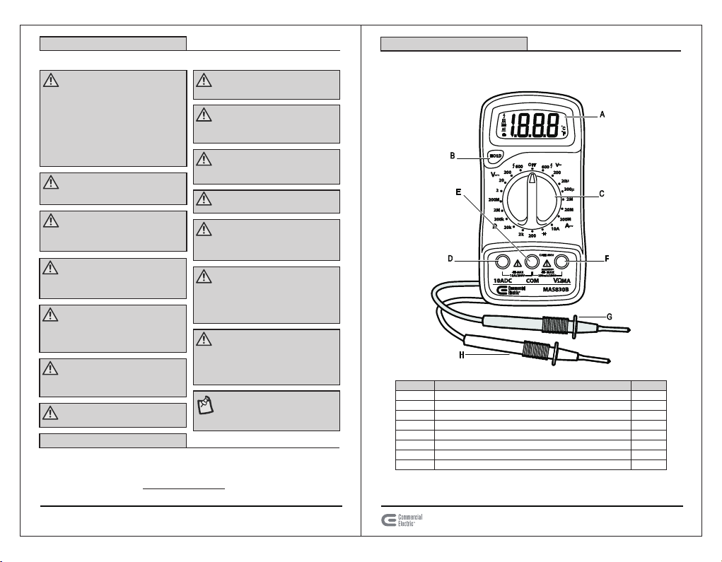
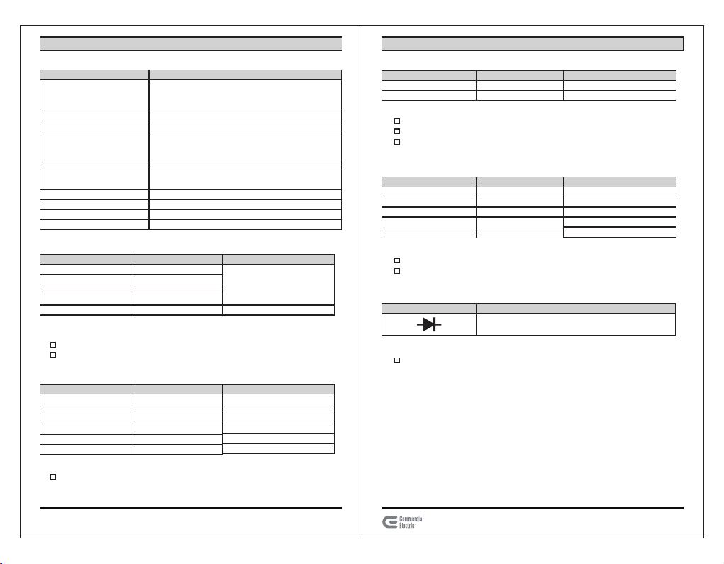
Parte Descripción Cantidad
1
1
1
1
F
G
H
Pantalla LCD
Botón para sostener
Interruptor giratorio
Conector de 10A, para las mediciones de 10A con la
punta de prueba roja
Conector COM, para la punta de prueba negra
Conector VΩmA, para todas las pruebas con punta de
prueba roja, excepto de 10A
Punta de prueba roja
Punta de prueba negra
Información de Seguridad (Continuación)
PRECAUCIONES
ADVERTENCIA: Cuando el medidor esté
conectado a un circuito de medición,
nunca toque los terminales no utilizados.
ADVERTENCIA: Nunca exceda los valores
de protección límite indicados en las
especificaciones para cada rango de
medición.
ADVERTENCIA: Antes de intentar insertar
transistores para probarlos, asegúrese
siempre de que se hayan desconectado
las puntas de prueba de los circuitos de
medición.
ADVERTENCIA: No conecte componentes
al tomacorriente hFE cuando este
realizando mediciones de voltaje con
puntas de prueba.
ADVERTENCIA: Nunca realice mediciones
de resistencia en circuitos energizados.
ADVERTENCIA: Nunca use el medidor
para medir voltajes que puedan
sobrepasar 600V sobre la tierra (pozo a
tierra) en instalaciones de Categoría II.
ADVERTENCIA: Siempre tenga cuidado
cuando trabaje con tensiones superiores
a 60V CD o 30V CA rms.
ADVERTENCIA: Mantenga sus dedos
detrás de las barreras de las puntas de
medición cuando este midiendo.
ADVERTENCIA: El tiempo de medición
para una alta corriente (10A) debería ser
menor a 10 segundos para cada
medición y el intervalo de tiempo entre
dos mediciones debe ser superior a
cinco minutos.
PRECAUCION: Antes de girar el selector
de rango para cambiar las funciones,
desconecte las puntas de prueba del
circuito bajo prueba.
NOTA: Cuando la escala de valor a ser
medida es desconocida antes de la
medición, coloque el selector de rango
en la posición más alta.
PRECAUCION: Al realizar mediciones en
un televisor o circuitos de entrada,
siempre recuerde que puede haber picos
de voltaje de gran amplitud en los
puntos de prueba, que los cuales pueden
dañar el medidor.
ADVERTENCIA: Este manual contiene
información y advertencias necesarias
para la operación segura y el
mantenimiento del medidor. Se
recomienda que lea y entienda este
manual de instrucciones antes de utilizar
el medidor. Si no entiende estas
instrucciones y si no puede cumplir con
las advertencias e instrucciones
contenidas en este documento puede
sufrir lesiones o daños graves.
ADVERTENCIA: El pleno cumplimiento de
las normas de seguridad solo se puede
garantizar mediante el uso de las puntas
de prueba suministradas.
ADVERTENCIA: La protección
proporcionada por el instrumento será
afectada si se utiliza de una manera no
especificada por el fabricante.
Garantía
GARANTÍA: 12 meses
Durante un año a partir de la fecha de compra, este producto está garantizado contra
cualquier defecto de materiales o mano de obra. Contacte al Equipo de Servicio al
Cliente al 1-877-527-0313 o visite www.HOMEDEPOT.com.
Pre-Funcionamiento
CONTENIDO DEL EMPAQUE
3 HOMEDEPOT.COM
Por favor, póngase en contacto con el 1-877-527-0313 para obtener más ayuda.
4

Componente
Voltaje máximo entre los
terminales y tierra (puesta
a tierra)
Fusible de protección
Batería
Precisión
Pantalla
Método de medición
Indicación de exceso
Indicación de polaridad
Ambiente de funcionamiento
Temperatura de almacenamiento
Especificación
CAT II 600V
F1 250mA/250V F2 10A/250V
Batería de 9V, NEDA 1604 o 6F22
La precisión se especifica para un período de un año
después de la calibración y al menos 18 a 28°C (64 a
82°F) con una humedad relativa de hasta 80 %.
LCD, cuenta hasta 1999, actualización de 2 a 3/seg.
Integración del concentrador de doble conexión y
convertidor Analógico / Digital
Solo figura "1" en la pantalla
se muestra "-" para la polaridad negativa
0°C - 40°C (32°F - 104°F), humedad relativa de 80 %
-10 °C - 50°C (14°F - 122°F)
Rango de Medición
20uA
200uA
2mA
20mA
200mA
Resolución
0.01uA
0.1uA
1uA
10uA
100uA
Precisión
±3% rdg ± 15dgt
10A 10mA
±1.5% rdg ± 10dgt
±1% rdg ± 8dgt
±1% rdg ± 8dgt
±1% rdg ± 5dgt
±1% rdg ± 5dgt
Rango de Medición
200V
600V
Resolución
100mV
1V
Precisión
±1.2% rdg ± 10dgt
±1.2% rdg ± 10dgt
Rango de Medición
200Ω
2kΩ
20kΩ
200kΩ
2MΩ
Resolución
0.1Ω
1Ω
10Ω
100Ω
1kΩ
Precisión
±1.0% rdg ± 5dgt
±0.8% rdg ± 2dgt
±0.8% rdg ± 2dgt
±0.8% rdg ± 2dgt
±0.8% rdg ± 5dgt
Pre-Funcionamiento (Continuación)
ESPECIFICACIONES DEL PRODUCTO
Rango de Medición
200mV
2V
20V
200V
600V
Resolución
100uV
1mV
10mV
100mV
1V
Precisión
±0. 5% rdg ± 3dgt
±0.8% rdg ± 5dgt
ESPECIFICACIONES DE VOLTAJE CC
Especificaciones Adicionales:
Protección de Sobrecarga: 250V rms
Para el rango de 200mV y 600V CD o rms. CA para otros rangos
ESPECIFICACIONES DE CC
Especificaciones Adicionales:
Protección de Sobrecarga: Fusible para el conector mA F 250mA/250V y
un fusible para el conector A F 10A/250V
ESPECIFICACIONES DE VOLTAJE CA
Especificaciones Adicionales:
Protección de Sobrecarga: 600V CD o rms. CA para todos los rangos
Rango de Frecuencia: 40 - 400 Hz
Respuesta: Respuesta promedio (calibrada en rms de la onda sinusoidal)
ESPECIFICACIONES DE RESISTENCIA
Especificaciones Adicionales:
ESPECIFICACIONES DE DIODO
Rango de Medición Función
Muestra la caída de tensión directa del diodo.
Especificaciones Adicionales:
Voltaje Máximo de Circuito Abierto: 3.2 V.
Protección de Sobrecarga: 250V CD o rms. CA para todos los rangos
Protección de Sobrecarga: 250V CD o 250V CA rms
5 HOMEDEPOT.COM
Por favor, póngase en contacto con el 1-877-527-0313 para obtener más ayuda.
6
Pre-Funcionamiento (Continuación)

CATII
A
C
F
E
HG
CATII
A
C
F
E
HG
REALIZANDO UNA MEDICION DE
VOLTAJE CC
2
REALIZANDO UNA MEDICION DE
VOLTAJE DE CC
1
Funcionamiento
Conecte la punta de prueba roja (G) al
conector VΩmA (F) y la punta de prueba
negra (H) al conector COM (E).
Ajuste el interruptor giratorio (C) a la
posición deseada de VCC.
NOTA: Cuando la escala de valor a
ser medida es desconocida antes
de la medición, coloque el selector
de rango en la posición más alta.
Conecte las puntas de prueba roja y
negra (G y H) a lo largo de la fuente o
la carga que se está midiendo.
Lea el valor del voltaje en la pantalla
del LCD (A) junto con la polaridad de
la conexión de la punta de prueba
roja (G).
Conecte la punta de prueba roja (G) al
conector VΩmA (F) y la punta de prueba
negra (H) al conector COM (E). Para las
mediciones entre 200mA y 10A, inserte
la punta de prueba roja (H) en el conector
de 10A (D).
Ajuste el interruptor giratorio (C) a la
posición deseada de VCA.
Abra el circuito en el que la corriente
va a ser medida y conecte las puntas
de prueba roja y negra (G y H) en serie
con el circuito.
Lea el valor de la corriente en la
pantalla LCD (A) junto con la
polaridad de la conexión de la punta
de prueba roja (G).
Funcionamiento (Continuación)
Conecte la punta de prueba roja (G)
al conector VΩmA (F) y la punta de
prueba negra (H) al conector COM (E).
Ajuste el interruptor giratorio (C) a
la posición deseada de VCA.
Conecte las puntas de prueba roja
y negra (G y H) a lo largo de la fuente
o la carga que se está midiendo.
Lea el valor del voltaje en la
pantalla LCD (A).
ADVERTENCIA: Si la resistencia a
medir está conectada a un
circuito, apague y descargue
todos los condensadores antes de
aplicar las puntas de prueba.
Conecte la punta de prueba roja (G)
al conector VΩmA (F) y la punta de
prueba negra (H) al conector COM (E).
Ajuste el interruptor giratorio (C) a la
posición de rango deseado Ω (omega).
Conecte las puntas de prueba roja y
negra (G y H) a lo largo del reostato
que se está midiendo.
Lea el valor de la resistencia en la
pantalla LCD (A).
REALIZANDO UNA MEDICION DE
VOLTAJE CA
3
REALIZANDO UNA MEDICION DE
RESISTENCIA
4
7 HOMEDEPOT.COM
Por favor, póngase en contacto con el 1-877-527-0313 para obtener más ayuda.
8
CATII
A
C
F
E
HG
D

CATII
A
C
F
E
HG
Compléter un teste de diode
5
Funcionamiento (Continuación)
Conecte la punta de prueba roja (G)
al conector VΩmA (F) y la punta de
prueba negra (H) al conector COM (E).
Ajuste el interruptor giratorio (C)
a la posición deseada de diodo
(indicada por un símbolo de flecha).
Conecte la punta de prueba roja
(G) al ánodo del diodo a probar y
la punta de prueba negra (H) al
cátodo del diodo.
La caída aproximada del voltaje
directo del diodo aparece en la
pantalla LCD (A).
Si la conexión es invertida, un
"1" aparece en la pantalla LCD (A).
Mantenimiento(Continuación)
REEMPLAZO DE LA BATERÍA Y FUSIBLE
ADVERTENCIA: Antes de abrir la
tapa de la batería, asegúrese de
que se hayan desconectado los
cables de prueba de los circuitos
de medición.
ADVERTENCIA: Cierre la tapa de la
batería y ajuste los tornillos antes
de usar el medidor con el fin de
evitar descargas eléctricas.
ADVERTENCIA: Si hay grietas o
roturas visibles en la carcasa o el
cable, deje de usar el medidor
inmediatamente.
PRECAUCION: Para una protección
continuada contra incendios,
reemplace el fusible de acuerdo
con el voltaje y rangos de
corriente especificados:
F1 250mA/250V a F2 10A/250V
(de acción rápida).
Si el icono de batería aparece en la pantalla LCD, esto indica que la batería necesita
ser reemplazada.
El fusible rara vez requiere ser reemplazado. Un fusible quemado suele ser el
resultado de un error del operador.
Para reemplazar la batería y el fusible
(250mA/250V) retire los dos tornillos
de la tapa de la batería que se encuentra
en la parte posterior del medidor. El
medidor se encuentra dentro de la funda.
Retire la funda para ver los tornillos.
Retire la batería o el fusible antiguo y
reemplácelos con una batería o
fusible de acuerdo con las
Especificaciones del Producto.
Cuidado y Limpieza
No use abrasivos o solventes en el
medidor.
Para limpiar use un paño húmedo y
un detergente suave solamente.
Mantenimiento
9 HOMEDEPOT.COM
Por favor, póngase en contacto con el 1-877-527-0313 para obtener más ayuda.
10

¿Preguntas, problemas, piezas faltantes? Antes de regresarlo
a la tienda, llame a Servicio al Cliente de Home Depot
1-877-527-0313
HOMEDEPOT. COM
Conserve este manual para referencia futura.
This manual suits for next models
1
Table of contents
Languages:
Other Commercial Electric Multimeter manuals