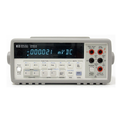
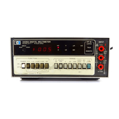
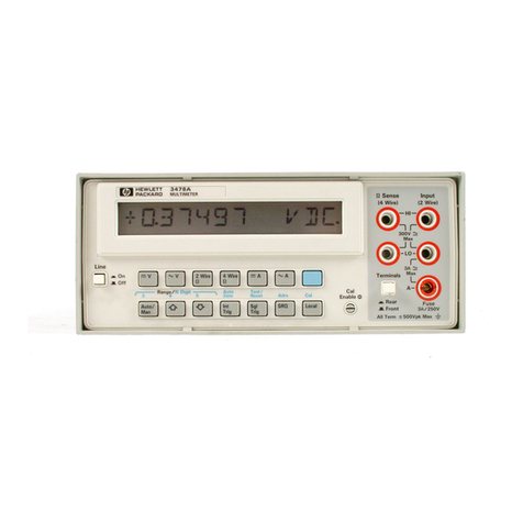
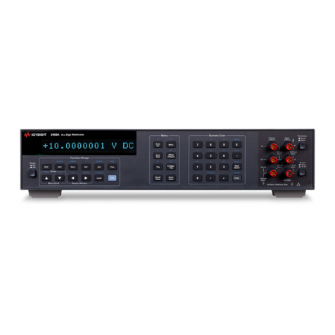
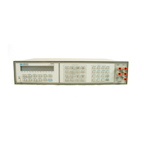
HP 3457A User manual

Errata
Title & Document Type:
Manual Part Number:
Revision Date:
HP References in this Manual
This manual may contain references to HP or Hewlett-Packard. Please note that Hewlett-
Packard's former test and measurement, semiconductor products and chemical analysis
businesses are now part of Agilent Technologies. We have made no changes to this
manual copy. The HP XXXX referred to in this document is now the Agilent XXXX.
For example, model number HP8648A is now model number Agilent 8648A.
About this Manual
We’ve added this manual to the Agilent website in an effort to help you support your
product. This manual provides the best information we could find. It may be incomplete
or contain dated information, and the scan quality may not be ideal. If we find a better
copy in the future, we will add it to the Agilent website.
Support for Your Product
Agilent no longer sells or supports this product. You will find any other available
product information on the Agilent Test & Measurement website:
www.tm.agilent.com
Search for the model number of this product, and the resulting product page will guide
you to any available information. Our service centers may be able to perform calibration
if no repair parts are needed, but no other support from Agilent is available.

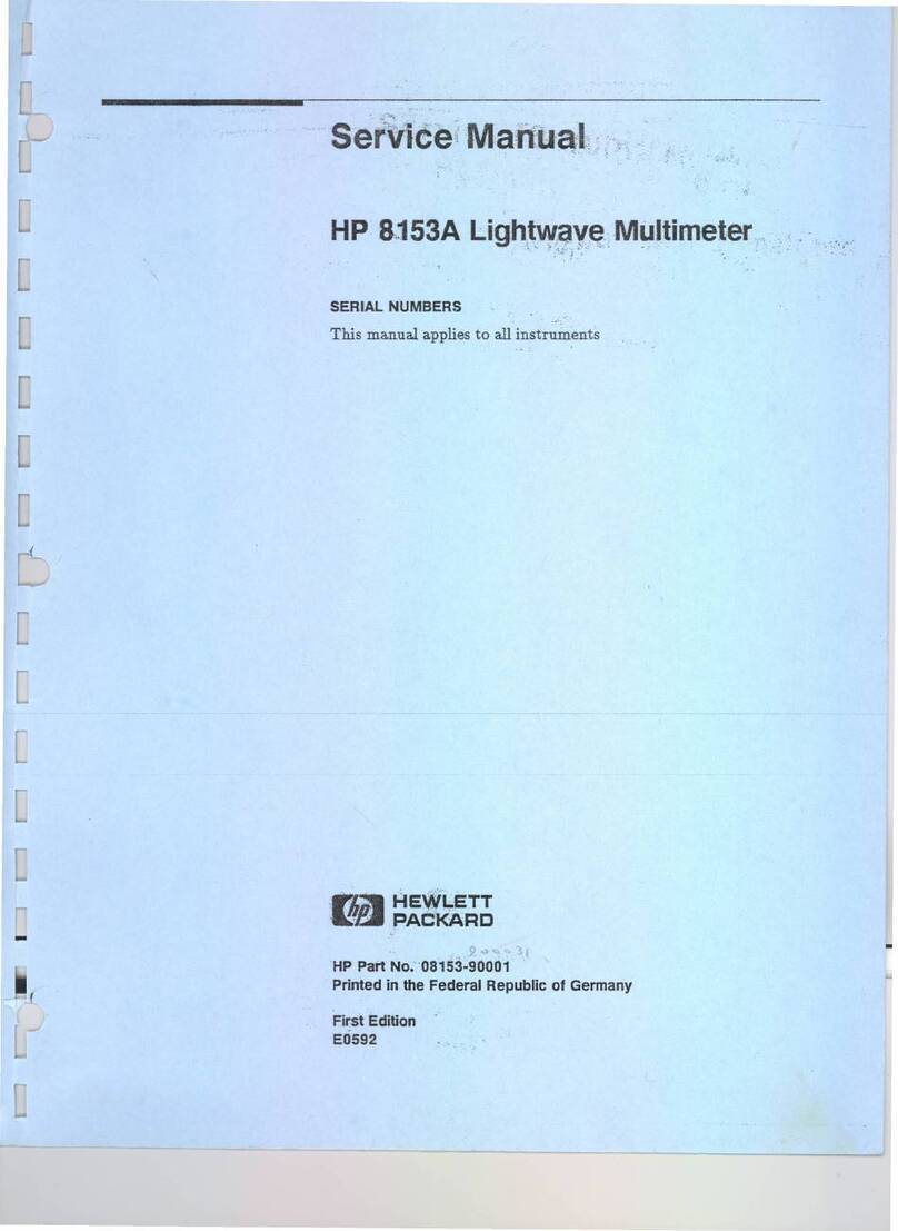
HP
3457A
Multimeter
Service
Manual
HEWLETT-PACKARD COMPANY
Loveland Instrument Division
P.O. Box 301
Loveland, Colorado 80537
MANUAL PART NO. 03457-90011
MICROFICHE PART NO. 03457-99011
Printed in U.S.A. May
1986

HEWLETT
PACKARD
SAFETY SUMMARY
The following general safety precautionsmust be observedduring all phases of operation,service, and repair of this instrument.
Failure to comply with these precautionsor with specific warnings elsewhere in this manual violates safety standardsof design,
manufacture, and intended use of the instrument. Hewlett-Packard Company assumes no liability for the customer's failure
to comply with these requirements.
GROUND THE INSTRUMENT
To
minimize
shock hazard, the instrument chassis and cabinet must be connected toan electr~calground
DO NOT OPERATE IN AN EXPLOSIVE ATMOSPHERE
Do not operate the Instrument In the presence of flammable gases or fumes
Operation
of any
electrical
Instrument In such an envlronment
constitutes
a deflnlte safety hazard.
KEEP AWAY FROM LIVE CIRCUITS
Operating
personnel must not remove Instrument covers. Component replacement and lnternal adjustments
must be made byquallfled maintenancepersonnel Under certaln condltlons, dangerous voltages may ex
1st even wlththe lnstrurnent swltched off. To avold
Injuries,
always
disconnect
Input voltages and
discharge
clrcults before touchlng them.
DO NOT SERVICE
OR
ADJUST ALONE
Do not attempt Internal service or adjustment unless another person, capable of
rendering
flrst a~dand
resuscltatlon,
IS
present.
DO NOT SUBSTITUTE PARTS
OR
MODIFY INSTRUMENT
Because of the danger of lntroduclng addltlonal hazards, do not Install substltute parts or perform any
unauthorized
modlflcatlon to the Instrument Return the lnstrurnent to a Hewlett-Packard Sales and Ser-
vice Offlce for servlce and repalr to ensure that safety features are malntalned
DO NOT OPERATE A DAMAGED INSTRUMENT
Whenever ~t1s posslble that the safety protection features bullt Into thls Instrument have been lmpalred,
elther through physlcal damage, excessive moisture, or any other reason, REMOVE POWER and do not
use the Instrument untll safe operation can be verlfled by servlce-tra~nedpersonnel If necessary, return
the Instrumentto a Hewlett-Packard Sales and Servlce Offlce for servlce and repalr toensure that safety
features are malntalned.

HEWLETT
PACKARD
Operating and Safety Symbols
Symbols Used On Products And In Manuals
-
LINE
4
AA
ATTENTION
Statlc
Sensltwe
AC line voltage input receptacle.
Instruction manual symbol affixed to product. Cautions the user to refer to
respective instruction manual procedures to avoid possible damage to the
product.
Indicates dangerous voltage
-
terminals connected to interior voltage
exceeding
1000
volts.
Protective conductor terminal. Indicates the field wiring terminal that must
be connected to earth ground before operating equipment
-
protects against
electrical shock in case of fault.
Clean ground (low-noise). Indicates terminal that must be connected to
earth ground before operating equipment
-
for single common connections
and protection against electrical shock in case of fault.
Frame or chassis ground. Indicates equipment chassis ground
terminal
-
normally connects to equipment frame and all metal parts
Affixed to product containing static sensitive devices
-
use anti-static
handling procedures to prevent electrostatic discharge damage to
components.
NOTE NOTE
Calls attention to a procedure, practice, or condition that requires special
attention by the reader.
CAUTION CAUTION
Calls attention to a procedure, practice, or condition that could possibly
cause damage to equipment or permanent loss of data.
WARNING WARNING
Calls attention to a procedure, practice, or condition that could possibly
cause bodily injury or death.

TABLE OF CONTENTS
Section
I
Page
........
GENERAL INFORMATION 1.1
1-1 Introduction ..............1.1
..........
1-3 Manual Description 1.1
.........
1-5 Instrument Description 1-2
.........
1-7 Safety Considerations 1.2
1-9 Instruments Covered by this Manual.
.
1.2
1-13 Specifications
.............
1-2
.......
1-15 Options and Accessories 1-24
1-17 Test Equipment
...........
1-25
Section
I1
Page
INSTALLATION
..............
2.1
2-1 Introduction
..............
2.1
2-3 Initial Inspection
............
2.1
..........
2-5 Preparation for Use 2.2
........
2-8 Line Voltage Selection 2.2
.............
2-10 Power Cords 2.2
.......
2-12 Grounding Requirements 2.3
2-14 Bench Use
..............
2.3
2-16 Rack Moiinting
............
2.3
.........
2-18 Interface Connections 2.4
2-19 Control Interface
...........
2.4
........
2-21 HP-1B Address Selection 2.4
2-23 Changing the Address from the
.............
Front Panel 2.5
2-24 Changing the Address from the
..............
Controller 2.5
2-25 InstaHation of Options
.........
2.6
2-28 Rear Terminal Assembly Removal
.
.
2.7
....
2-30 Plug-In Assenlbly Installation 2.8
...
2-32 Plug-In Assen~blyConfig~~ration 2.9
2-38 Wiring Block Preparation
.....
2-1
1
Section I11 Page
OPERATION
................
3.1
3-1 Introduction
..............
3.1
3-3 General Information
..........
3.1
3-4 AC Power
..............
3.1
3-6 Power On
...............
3.1
................
3-9 Operation 3.1
3-1
1
Voltage Measurements
........
3.
1
3-18 Resistance Measurements
.......
3.3
3-25 Current Measurements
........
3.4
3-32
Frequent
y
/Period Measurements .
.
3.6
3-39 HP 44491A General Purpose
Multiplexer
.............
3.6
3-45 HP44492A Reed Relay .......3.8
M~~ltiplexer
.............
3.8
Section 1V Page
..........
PERFORMANCE TESTS 4.1
4-
1
Introduction
..............
4.1
.........
4-3 Equipment Required 4.1
..............
4-5 Test Record 4.1
...........
4-7 Calibration Cycle 4.1
..........
4-9 Test Considerations 4.1
...............
4-10 General 4.1
4-12 Performance Tests
..........
4.2
DC Voltage Performance Tests
.......
4.2
...........
4-13 Preliminary Steps 4.2
4-14 DC Voltage Function
.
Offset Test
.
.4.2
.
...
4-16 DC voltage Function Gain Test 4.3
4-18 DC Voltage Function
.
Linearity
Test
.................
4.4
.......
AC Voltage Performance Tests 4.4
.
...
4-20 AC Voltage Function Gain Test 4.4
4-22 AC Voltage Function
.
Frequency
Response Test
............
4.5
DC Current Performance Tests
.......
4.7
4-24 DC Current Function
.
Offset Test
.
.4.8
4-26 DC Current Filnction
.
Gain Test
.
.4.8
AC Current Performance Tests
.......
4.9
.
...
4-28 AC Current Function Gain Test 4.9
2-Wire Ohms Performance Tests
.....
4-10
4-30 2-Wire Ohms Function
.
Offset
................
Test 4-10
4-32 2-Wire Ohms Function
.
Gain Test . 4-1
1
.....
4-Wire Ohms Performance Tests 4-11
4-34 4-Wire Ohms Function
.
Offset
................
Test 4-12
4-36 4-Wire Ohms Function
.
Gain Test . 4-13
Frequency Counter Performance Tests
.
.
4- 13
4-38 Frequency Counter
.
Acwracy
................Test 4-14
Rear lnput Performance Tests (Standard
............
Instrument) 4-14
4-40 Preliminary Steps ..........4-14
4-41 DC Voltage Function
.
Rear Terminal
Offset Test ............4-14
4-43 DC Ciu-rent Function
.
Rear Terminal
............
Offset Test
4-15
4-45 2-Wire Ohms F~tnction
.
Offset
................
Test 4-15
4-47 4-Wire Ohms F~unction
.
Offsct
Test
................
4-16
Rear Input Performance Tests (4449
l
A
General Purpose Relay Assy)
...
4-17
4-49 Preliminary Steps
..........
4-17

TABLE OF CONTENTS (Cont'd)
Section 1V Page
PERFORMANCE TESTS (Cont'd)
4-50 DC Voltage Function
.
4449
1
A
Offset Test
............
4-17
4-52 2-Wire Ohms Function
.
4449
1
A
Offset Test
............
4-18
4-54 4-Wire Ohms Function
.
44491A
Offset Test
............
4-18
4-56 DC Current Function
.
4449
1
A
Offset Test
............
4-19
Rear Input Performance Tests (44492A
10 Channel Multiplex Assy)
....
4-20
4-58 Preliminary Steps ..........4-20
4-59 DC Voltage Function
.
44492A
Offset Test
............
4-20
4-61 2-Wire Ohms Function
.
44492A
............
Offset Test 4-2
1
4-63 Operational Verification Tests
...
4-22
DC Voltage Operational Verification
Tests
................
4-22
4-65 Preliminary Steps
..........
4-22
4-66 DC Voltage Function
.
Offset Test . 4-22
4-68 DC Voltage Function
.
Gain Test
. .
4-23
AC Voltage Operational Verification
................
Tests 4-24
4-70 AC Voltage Function
.
Gain Test
.
. 4-24
4-72 AC Voltage Function
.
Frequency
...........
Response Test 4-24
DC Current Operational Verification
................
Tests 4-25
4-74 DC Current Function
.
Offset Test. 4-26
4-76 DC Current Function
.
Gain Test . 4-26
AC Current Operational Verification
................
Tests 4-27
4-78 AC Current Function
.
Gain Test.
.
4-27
2-Wire Ohms Operational Verification
................
Tests 4-27
4-80 2-Wire Ohms F~~nction
.
Offset
................
Test 4-27
4-82 2-Wire Ohms Function
.
Gain Test . 4-28
4-Wire Ohms Operational Verificat'
on
................
Tests 4-29
4-84 4-Wire Ohms F~inction
.
Offset
................
Test 4-29
4-86 4-Wire Ohms Function
.
Gain Test . 4-30
Frequency Counter Operational
.........
Verification Tests 4-3
1
4-88 Frequency Counter
.
Accuracy
................
Test 4-31
Rear Input Operational Verification
....
Test (Standard Instrument) 4-32
Section 1V
PERFORMANCE TESTS (Cont'd)
4-90 Preliminary Steps
.......
4-91 DC Voltage Function
.
Rear
Terminal OFfset Test
....
4-93 DC Current Function
.
Rear
Terminal Offset Test
....
4-95 2-Wire Ohms Function
.
Reas
Terminal Offset Test
....
4-97 4-Wire Ohms Function
.
Real-
Terminal Offset Test
....
Rear Input Operational Verification
Page
.
4-32
. 4-33
. 4-33
.
4-33
.
4-33
Tests (4449
1
A General Purpose
Relay Assy)
...........
4-34
4-99 Preliminary Steps
.........
4-34
4-100 DC Voltage F~unction
.
44491A
Offset Test
...........
4-35
4-102 2-Wire Ohms Function
.
44491A
Offset Test
...........
4-35
4-104 4-Wire Ohms Function
.
44491A
Offset Test ...........4-35
4-106 DC Current Function
.
4449
l
A
Offset Test
...........
4-36
Rear Input Operational Verificat'ton
Test (44492A 10 Channel Multiplex
Assy)
..............
4-36
4-108 Preliminary Steps
.........
4-37
4-109 DC Voltage Function
.
44492A
Offset Test
...........
4-37
4-1 11 2-Wise Ohms Function
.
44492A
........
Offset Test Limits 4-37
Section V Page
CALIBRATION
..............
5.1
5-1 Intsoduction
.............
5.1
5-4 Calibration Security
.........
5.1
5-6 Security Code
...........
5.
I
5-8 Changing the Security Code
....
5.1
5-10 Calibration Number
.........
5.2
5-13 Preliminary Calibration
Procedures
............
5.3
5-15 Input Amplifier Offset
............
Adjustments 5.4
5-17 AC Convertor Frequency
.......
Response Adjustment 5.4
5-19 Calibration Procedures
.
Front
Panel Inputs
............
5.5
5-21 DC Volts Offset Calibration
....
5.5
.....
5-23 DC Volts Gain Calibration 5.6
...
5-25 DC Volts Linearity Calibration 5.6

TABLE OF CONTENTS
(Cont'd)
Section V Page
CALIBRATION (Cont'd)
5-27 2-Wire Ohms Offset Calibration
...
5.8
....
5-29 2-Wire Ohms Gain Calibration 5.7
5-3
1
4-Wire Ohms Offset Calibration
...
5.8
....
5-33 4-Wire Ohms Gain Calibration 5.9
...
5-35 DC Current Offset Calibration 5-10
....
5-37 DC Current Gain Calibration 5-10
5-39 AC Volts Offset
&
Gain
............
Calibration 5-11
.......
5-41 AC Current Calibration 5-11
.......
5-43 Frequency Calibration 5-12
5-45 Calibration Procedures Rear Panel
Inputs
...............
5-12
....
5-47
DC
Volts Offset Calibration 5-12
5-49 2-Wire Ohms Offset Calibration
. .
5-13
5-51 4-Wire Ohms Offset Calibration
.
.
5-14
...
5-53 DC Current Offset Calibration 5-14
5-55 Calibration Procedures
.
4449
1
A
General Purpose Relay Assy
...
5-15
......
5-56 Wiring Block Preparation 5-15
....
5-58 DC Volts Offset Calibration 5-16
5-59 2-WireOhmsOffset Calibration
. .
5-17
5-60 4-Wire Ohms Offset Calibration
. .
5-17
...
5-61 DC Current Offset Calibration 5-17
5-62 Calibration Procedures
.
44492A
....
10 Channel Milltiplex Assy 5-18
......
5-63 Wiring Block Preparation 5-18
....
5-65 DC Volts Offset Calibration 5-19
5-66 2-Wire Olms Offset Calibration
. .
5-19
Section V1 Page
REPLACABLE PARTS
...........
6.1
6-1 lntrodi~ction
..............
6.1
.........
6-3 Ordering Infornlation 6.1
6-4 Listed Parts
.............
6.1
6-6 Non-Listed Parts
...........
6.
1
......
6-8 Direct Mail Order System 6.1
6-1
1
Part Changes
.............
6.2
Section VI Page
REPLACABLE PARTS (Cont'd)
...........
6-13 Proprietary Parts 6.2
6-15 Disassembly/Assembly Procedures
.
.
6.3
6-17 Rear Terminal Assembly Removal
.
6.3
6-19 Optional Plug-In Assembly
Removal
...............
6.3
.........
6-2
1
Top Cover Removal 6.4
6-25 Digital (A1) Assembly Renioval
...
6.4
6-27 Plug-In Support Assembly
Removal
...............
6.5
6-29 AC Convertor (A3) Assembly
Removal
...............
6.5
...
6-3
1
Analog (A2) Assembly Removal 6.5
........
6-33 Front Panel Removal 6.6
Section V11 Page
...........
MANUAL CHANGES 7.1
..............
7-1
Introduction 7.
1
Section VllI Page
8-1 Introduction
..............
8.1
.........
8-3 Safety Considerations 8.1
............
8-8 Static Handling 8.2
....
8-12 Recommended Test Equipment 8.2
.........
8-14 Theory of Operation 8.2
.............
8-15 Introduction 8.2
......
8-18 Chassis Common Section 8.2
.......
8-23 Floating Comon Section 8.3
.........
8-32 Self Test Description 8.4
8-33 Power On Seq~lence
.........
8.4
8-36 Self Test
...............
8.5
8-39 Troi~bleshooting
............
8.5
8-40 Introduction
.............
8.5
8-42 Al Assembly Failure Indications
.
.
8.5
8-46 A2/A3 Assembly Failure
indications
.............
8.6
8-50 Replacement Procedures
......
8.6

SECTION I
GENERAL INFORMATION
1-1.
INTRODUCTION
1-2.
This manual contains information relating to the installation, operation, performance testing, calibration, and
service of the
HP
3457A Multimeter. The information is designed for the use of service trained personnel. Other
users should refer tothe
HP
3457A Operating Manual.
1-3.
MANUAL DESCRIPTION
1-4.
The following paragraphs provide a general description of the manual layout and content:
Section I. General Information
Section
I
contains a brief description of the manual, and a general description of the instrument. This
section also contains the instrument specifications and information concerning options and accessories.
Section II. InstallationProcedures
Section
11
contains information to prepare the
HP
3457A for use. Included in this section is power
requirements, line voltage selection, and interfacing information.
Section Ill. Operating Instructions
Section
I11
contains operating instructions necessary to service the HP 3457A. These operating instruc-
tions are a condensed version of those contained in the Operating, Programming and Configuration
Manual.
Section IV. Performance Tests
Section
IV
contains information and procedures required to test the
HP
3457A to its rated specifica-
tions. Also included
in
this section is a condensed version of the performance test (operational verifica-
tion test) which will provide a more rapid test and give a
90%
confidence that the instrument will meet
its specifications.
Section V. Calibration
Section
V
contains procedures required to calibrate the
HP
3457A to its rated specifications.

General Tnformation
Section VI. Replaceable Parts
Section VI lists part numbers for cabinet parts and printed circuit assemblies.
Section VII. Manual Backdating
Section VII contains information required to adapt this manual to instruments whose serial numbers are
lower than those listed on the title page.
Section VIII. Service
Section VIIl contains a block diagram theory of operation, schematic diagrams, and procedures to aid in
troubleshooting the HP
3457A.
1-5.
INSTRUMENT DESCRIPTION
1-6. The
HP
3457A is a versatile high precision digital multimeter which measures ac or dc volts, ac or dc current,
ac+dc volts or current, resistance, freq~~encyand period. It measures voltages up to 300 Vac or 300 Vdc with high
dc resolution and accuracy. The instrument is designed for both bench and system use. Program and reading
storage are included to allow high speed measuren~entapplications with reading rates of greater-than 1000 read-
ings per second. Provision has been made for optional assemblies such as
a
general purpose scanner or m~rltiplexer
assembly.
1-7.
SAFETY CONSIDERATIONS
1-8.
The
HP
3457A
is
a safety class
1
instrument (provided with
a
protective earth terminal). The instrument and
manual should be reviewed for safety markings and instructions before operation. Refer to the Safety S~rmmary
preceding this section for appropriate safety instructions and markings covering this instrument.
1-9.
INSTRUMENTS COVERED BY THIS MANUAL
1-10. Instruments covered by this manual are identified by a serial number prefix listed on the title page.
Hewlett-Packard uses a two part serial number in the form
XXXXAYYYYY,
where
xxxx
is the serial prefix,
A
is the
country of origin (A=USA) and
YYYYY
is the serial suffix. The serial number prefix identifies a series of identical
instruments. The serial number suffix is assigned sequentially and is unique to each instrument.
1-1
1.
If
the serial number prefix of your instrument
is
greater than the one listed on the title page, a yellow
Manual Changes supplement will explain how to adapt this manual to your instrument.
1-12.
If
the serial number prefix of
YOLII.
instrument is lower than the one listed on the title page, information
contained in Section
VII
(Manual Backdating) will explain how to adapt this manual to your instrument.
1-1
3.
SPECIFICATIONS
1-14.
Specifications for the
HP
3457A Multimeter are listed in Table
1-1.
These specifications are the perfor-
mance standards which the instrument is guaranteed to meet.

3457A
General
Information
Table
1-1.
Specifications
DC
VOLTS
INPUT CHARACTERISTICS:
MAX
I
MUM
READ
1
NG
3.030000
V
RESOLUTION
6
1/2
digits
5
1/2
digits
4
1/2
digits
3
1/2
digits
INPUT RESISTANCE (OHMS):
30
millivolt through
3
volt range
-
10
gigaohms
30
volt and
300
volt range
-
10
megohms
(+/-
1%)
MAXIMUM INPUT VOLTAGE: (non-destructive)
HI
or
LO
to Earth Ground:
*
450V
peak
MEASUREMENT ACCURACY:
f(%
of reading
+
Number of Counts)
Auto-Zero ON
24
HOUR: Tcal
*
1
OC
2
hour warm-up Accuracy relative to calibration standard
24
hour specifications apply if the instrument is calibrated between
90
and
100%
of
full-scale. For calibration between
33
and
90%
of full-scale, add
.00015%
to
%
Reading.
RANGE
30
mV
300
mV
3
v
30
V
300
V
t
READING
0.0012
0.0005
0.00035
O.OOO65
O.OO25
100
PLC*
6 1/2
digits
NUMBER OF COUNTS
10
PLC*
6 1/2
digits
1
PLC*
6 1/2
digits
.005
PLC*
4 1/2
digits
.I
PLC*
5 1/2
digits
.0005
PLC*
3 1/2
digits
90
DAY: Tcal
5
5'~After
1
hour warm-up
RANGE
I
%
READING
I
NUMBER OF COUNTS
100
PLC*
6 1/2
digits
.005
PLC*
1/2
digits
10
PLC*
6
1/2
digits
.0005
PLC*
3 1/2
digits
1
PLC*
6 1/2
digits
.I
PLC*
5
1/2
digits

General Information
Table
1-1.
Specifications
DC
VOLTS
(Contyd)
1
YEAR: Tcal
*
5'~After
1
hour warm-up
RANGE
30
mV
300
mV
3
v
30
V
300
V
10
PLC*
6
1/2
digits
%
READING
0.0045
0.0035
0.0025
0.0040
0.0055
100
PLC*
6 1/2
digits
365
3
9
6
19
6
NUMBER
OF
COUNTS
*
PLC
=
Integration Time in Power Line Cycles. When using integration times of
100
PLC,
10
PLC,
or IPLC; multiply Number of Counts in the Measurement Accuracy Tables by
0.1
for
5 1/2
digit
readings,
0.01
for
4 1/2
digit readings and
0.001
for
3 1/2
digit readings.
Tcal
=
the temperature of the environment where the
3457A
was calibrated. Calibration should
be
performed with the environment temperature between
18
and
28
degrees centigrade.
1
PLC*
6 1/2
digits
500
50
7
30
7
-005
PLC*
4 1/2
digits
19
4
4
4
4
TEMPERATURE COEFFICIENT:
'(%
of Reading
+
Number of ~ounts)/'~
6
1/2
Digits Displayed
.I
PLC*
5 1/2
digits
70
9
4
7
4
.0005
PLC*
3 1/2
digits
6
4
4
4
4
Auto-Zero OFF*
-0005
+
40
.0005
+
13
.0005
+
10.3
.0005
+
11.0
.0005
+
10.3
*
Specifications given are for a stable environment
(k
I'c) and over a ten minute period.
Multiply Number of Counts by
0.1
for
5 1/2
digit readings,
0.01
for
4 1/2
digit
readings and
0.001
for
3
1/2
digit readings.
NOISE REJECTION:
With
1
Kohm imbalance in the LO lead and line frequency
(50
or
60
Hz)
*
0.08%.
INTEGRATION TIME
100
PLC
AC NMR
DC CMR
140
db
10
PLC
/
1
PLC
I
.I
PLC
1
-005
PLC
1
.0005
PLC

3457A
General Information
Table
1-1.
Specifications
DC VOLTS (Contyd)
MAXIMUM READING RATES: (Readings/Second)
INTEGRATION
I
DIGITS
I
READING RATE
DISPLAYED
0.005 PLC
0.1 PLC
1 PLC 6 1/2
10 PLC 6 1/2
100 PLC
Reading Rates apply with the keyboard Lock ON, Auto-Ze
8
OFF, Display OFF, Math Func-
tion OFF, Delay Time set to 0.0, Manual ranging, readings stored in internal memory
using Timer Trigger and single precision integer format.
DC CURRENT
INPUT CHARACTERISTICS:
MAX
I
MUM
READ
I
NG
6 1/2 digits
RESOLUTION SHUNT
RESISTANCE
1000 Ohm
100 Ohm
10 Ohm
1 Ohm
.I
ohm
4
1/2 digits 3 1/2 digits
I
6 1/2 digits 15 1/2 digitsRANGE
300 uA
3 mA
30 mA
300 mA
1 A
MAXIMUM BURDEN VOLTAGE: 0.35V
-
300uA, 3mA and 30mA ranges. 0.6V
-
300mA range. 1 V
-
1A range.
MEASUREMENT ACCURACY:
*(%
of reading
+
Number of Counts)
After 1 hour warmup, with Auto-zero ON.
24
HOUR: Tcal
5
1
OC
After two hour warm-up. Accuracy relative to calibration standard.
RANGE
300 uA
3 mA
30 mA
300 mA
1
A
%
READING
0.0020
0.002
0.0020
NUMBER
1 PLC*
6 1/2 digits
F COUNTS
.I
PLC*
5 1/2 digits .005 PLC*
4
1/2 digits
100 PLC*
6 1/2 digits .0005 PLC*
3
1/2 digits
10 PLC*
6 1/2 digits

Table
1-1.
Specifications
DC CURRENT (Cont9d)
90
DAY: Tcal
+
5'~
After one hour warm-up.
RANGE
1
YEAR: Tcal
f
5'~
After one hour warm-up.
%
READING
100
PLC*
6 1/2
digits
104
104
104
204
604
10
PLC*
6 1/2
digits
104
104
104
204
604
NUMBER
OF
COUNTS
1
PLC*
6 1/2
digits
115
115
115
215
615
RANGE
.0005
PLC*
3
1/2
digits
%
READING NUMBER OF COUNTS
.I
PLC*
5 1/2
digits
14
14
14
24
64
100
PLC*
6 1/2
digits
104
104
104
204
604
*
PLC
=
Integration Time in Power Line Cycles. When using integration times of
100
PLC,
10
PLC,
or IPLC; multiply Number of Counts in the Measurement Accuracy Tables by
0.1
for
5
1/2
digit
readings,
0.01
for
4 1/2
digit readings and
0.001
for
3
1/2
digit readings.
Tcal
=
the temperature of the environment where the
3457A
was calibrated. Calibration should
be performed with the environment temperature between
18
and
28
degrees centigrade.
.005
PLC*
4 1/2
digits
5
5
5
6
10
.005
PLC*
4 1/2
digits
TEMPERATURE COEFFICIENT:
*(%
of Reading
+
Number of ~ounts)/'~
6 1/2
Digits Displayed
10
PLC*
6 1/2
digits
104
104
104
204
604
.0005
PLC*
3
1/2
digits
Auto-Zero OFF*
*
Specifications given are for a stable environment
(*
I'c)
and over a ten minute period.
Multiply Number of Counts by
0.1
for
5 1/2
digit readings,
0.01
for
4 1/2
digit
readings and
0.001
for
3
1/2
digit readings.
1
PLC*
6 1/2
digits
115
115
115
215
615
.I
PLC*
5 1/2
digits
14
14
14
24
64

General Informatiol~
Table
1.1.
Specifications
DC CURRENT (Cont
'd)
MAXIMUM READING RATES: (Readings/Second)
INTEGRATION
TIME
0.0005 PLC
0.005 PLC
0.1 PLC
1 PLC
10 PLC
100 PLC
DIGITS
DlSPLAYED
I
READING RATE
Reading Rates apply with the keyboard lock ON, Auto-Zero OFF, Display OFF, Math Func-
tion OFF, Delay Time set to 0.0, Manual ranging, readings stored in internal memory
using Timer Trigger and single precision integer format.
RESISTANCE
(2-Wire Ohms, 4-Wire Ohms, Offset Compensated Ohms)
6
1/2 digits
INPUT CHARACTERISTICS:
10 uOhm
100 uOhm
1 mOhm
10 mOhm
100 mOhm
1
Ohm
10 Ohm
100 Ohm
1 KOhm
RANGE
(OHMS)
30
300
3
k
30 k
300
k
3 M
30 M
300 M*
3
G*
5
1/2 digits
100 uOhm
1 mOhm
10 mOhm
100 mOhm
1 Ohm
10 Ohm
100 Ohm
1
KOhm
10 KOhm
MAX
I
MUM
READING
6
1/2 digits
30.30000 Ohm
303.0000 Ohm
3.030000KOhm
30.30000KOhm
303.0000KOhm
3.030000MOhm
30.30000MOhm
303.0000MOhm
3.030000GOhm
RESOLUTION
4 1/2 digits
1 mOhm
10 mOhm
100 mOhm
1 Ohm
10 Ohm
100 Ohm
1
KOhm
10 KOhm
100 KOhm
3 1/2 digits
10 mOhm
100 mOhm
1 Ohm
10 Ohm
100 Ohm
1 KOhm
10 KOhm
100 KOhm
1
MOhm
CURRENT
THROUGH
UNKNOWN
*
On the Extended Ohms ranges (300 MOhm
&
3 GOhm), the current source is 100 nA in
parallel with 10 MOhms.
INPUT PROTECTION: (non-destructive)
HI sense to LO sense:
f
350~peak.
HI or LO to Earth ground: f450~peak.
MAXIMUM OPEN CIRCUIT VOLTAGE:
30 Ohm to 3 Megohm ranges: 12 volts
30 Megohm to 3 Gigaohm ranges: 8.5 volts

General Inform
B
t'
]on
3457A
Table
1-1.
Specifications
RESISTANCE (Cont
'd)
MEASUREMENT ACCURACY
-
FOUR-WIRE OHMS:
f
(%
of reading
+
Number of Counts)
Auto-zero
ON.
24
HOUR: Tcat
f
1°c
After two hour warm-up. Accuracy relative to calibration standard.
100
PLC*
6 1/2
digits
215
24
5
5
6
12
80
RANGE
(OHMS)
90
DAY: Tcal
f
5'~
After one hour warm-up.
%
READINC
10
PLC*
6 1/2
digits
235
25
6
6
7
14
83
1
YEAR: Tcal
f
5'~
After one hour warm-up.
1
PLC*
6 1/2
digits
350
35
6
6
8
16
93
RANGE
(OHMS)
30
300
3K
30 K
300 K
3M
30
M
RANGE
I
%
READING
1
(OHMS)
30
300
3 K
30 K
300 K
3
M
30
M
%
READING
0.0065
0.0045
0.0035
0.0035
0.004
0.0055
0.025
NUMBER
OF
COUNTS
100
PLC*
6
1/2
digits
315
34
6
6
7
12
8
0
I
0.0075
0.0055
0.005
0.005
0.005
0.0065
0.04
10
PLC*
6 1/2
digits
335
3
5
7
7
8
14
83
100
PLC*
6 1/2
digits
315
34
6
6
7
12
80
.I
PLC*
5 1/2
digits
55
6
4
4
4
7
14
.005
PCC*
4 1/2
digits
17
4
4
4
4
5
6
NUMBER
OF
COUNTS
.0005
PLC*
3 1/2
digits
1
PLC*
6 1/2
digits
450
45
7
7
9
16
93
NUMBER
.I
PLC*
5 1/2
digits
65
8
4
4
4
7
14
10
PLC*
6 1/2
digits
.005
PLC*
4 1/2
digits
18
4
4
4
4
5
6
1
PLC*
6
1/2
digits
.0005
PLC*
3 1/2
digits
.0005
PLC*
3
1/2
digits
6
4
4
4
4
5
5
F
COUNTS
.I
PLC*
5 1/2
digits
6
5
8
4
4
4
7
14
.005
PLC*
4 1/2
digits
18
4
4
4
4
5
6

General
Lnformation
Table
1-1.
Specifications
RESISTANCE (Cont
'd)
MEASUREMENT ACCURACY
-
TWO-WIRE OHMS:
*(%
of reading
+
number of counts)
Auto-zero
ON.
24
HOUR: Tcal
f
I0c
After two hour warm-up.
RANGE
(OHMS)
30
300
3
K
30
K
300
K
3
M
30
M
300
M*
3
G*
*
%
READING
0.003
0.0015
0.001
0.001
0.001
0.003
0.02
0.6
6.0
NUMBER
1
PLC*
6 1/2
digits
F
COUNTS
.I
PLC*
5 1/2
digits
20055
2006
204
24
6
7
14
100
100
100
PLC*
6 1/2
digits
10
PLC*
6
1/2
digits
.005
PLC*
4 1/2
digits
.0005
PLC*
3
1/2
digits
,pecifications apply for a stable environment (*lOc) and after Ohms Auto-Cal (Auto-Cal
3).
90
DAY: Tcal
+
~OC
After one hour warm-up.
RANGE
(OHMS)
X
READING NUMBER OF COUNTS
.0005
PLC*
3
1/2
digits
100
PLC*
b
1/2
digits
10
PLC*
5
1/2
digits
1
PLC*
6
1/2
digits
.I
PLC*
5
1/2
digits
-005
PLC*
4
1/2
digits

General Tnf ormation
Table
1-1.
Specifications
RESISTANCE (Contyd)
1
YEAR: Tcal
f
5'~
After one hour warm-up.
100 PLC*
5
1/2 digits
6
RANGE
(OHMS) 10 PLC*
1/2 digits
%
READING NUMBER OF COUNTS
1
PLC*
5
1/2 digits
.I
PLC*
5
1/2 digits .005 PLC* .0005 PLC*
3
1/2 digits
*
PLC
=
Integration Time in Power Line Cycles. When using integration times of 100 PLC, 10 PLC,
or IPLC; multiply Number of Counts in the Measurement Accuracy Tables by 0.1 for 5 1/2 digit
readings, 0.01 for 4 1/2 digit readings and 0.001 for
3
1/2 digit readings.
Tcal
=
the temperature of the environment where the 3457A was calibrated. Calibration should
be performed with the environment temperature between 18 and 28 degrees centigrade.
TEMPERATURE COEFFICIENT:
*(%
of Reading
+
Number of counts)/
'C
6
1/2 Digits Displayed
RANGE Auto-Zero ON Auto-Zero OFF*
*
Specifications given are for a stable environment
(*
I'c)
and over a ten minute period.
For integration times of
>=
1 PLC, multiply Number of Counts by 0.1 for 5 1/2 digit
readings, 0.01 for 4 1/2 digit readings and 0.001 for
3
1/2 digit readings.

General Information
Table
1-1.
Specifications
RESISTANCE (Cont'd)
MAXIMUM LEAD
RESISTANCE
FOUR-WIRE OHMS
1
Ohm
10
Ohm
100
Ohm
1
KOhm
10 KOhm
100
KOhm
1 MOhm
not applicable
not applicable
MAXIMUM OFFSET
lOLTAGE FOR OFFSET
COMPENSATED OHMS
(FULL SCALE)
1
mV
10
mV
100
mV
not applicable
not applicable
not applicable
not applicable
not applicable
not applicable
'RE
-
PROGRAMMED
SETTLING TIME
560
usec
350
usec
350
usec
350
usec
2.4
msec
24
msec
240
msec
2.4
sec
2.5
sec
curacy specification with pre-programmed settling times and
<200
pF
DIGITS
DlSPLAYED
3
1/2
4 1/2
5 1/2
6 1/2
6 1/2
6
1/2
READING RATE

General
Information
Table
1-1.
Specifications
TRUE RMS AC VOLTAGE
(AC
and
DC
Coupled)
INPUT CHARACTERISTICS:
MAX
I
MUM
READ1NG
3.250000 V
RESOLUTION
INPUT IMPEDANCE:
1
megohm *I% shunted
by
c
90 pF
(
<
115 pF rear input).
MAXIMUM INPUT VOLTAGE: (non-dest~uctive)
Input Terminals:
I'
450V peak.
HI or
LO
to Earth Ground:
k
450V
pcak.
CREST FACTOR: 3.5 to 1 at full-scale.
MEASUREMENT ACCURACY
-
AC COUPLED:
f
(%
of reading
+
number of counts)
Specifications apply for sine-wave inputs
>
10% of range with DC component
<
10% of the AC
component, with Auto-zero ON, AC slow filter ON (ACBAND 201, and after 2 hour warm-up.
For AC inputs between 3% and 10% of full-scale and
<
20KHz, add 0.7% to the percent of read
ing figures.
For pre-programmed settllng times, add
.I%
of input voltage step to accuracy specifications
for the first reading.
24 HOUR: Tcal
I0c
(ACV Function) After 2 hour warm-up Accuracy relative to calibration standard
30 mV to 30 V ranges.
FREQUENCY PERCENT
0
F
READING
>=
I
PLC
6
1/2 digits
NUMBER
(
0.1 PLC
5 1/2 digits
COUNTS
.005 PLC
4 1/2 digits -0005 PLC
3 l/2 digits

Table
1-1.
Specifications
General
Information
-
-
--
-
-
-
.
-
-
TRUE
RMS
AC
VOLTAGE (Cont'd)
24 HOUR: Tcal
k
I'C
(ACV Function) After 2 hour warm-up Accuracy relative to calibration standard
300 V range.
FREQUENCY PERCENT
0
F
READ
I
NG
90 DAY: Tcal
rf:
S'C
(ACV Function) After 1 hour warm-up
NUMBER OF COUNTS
30 mV to 30 V ranges
FREQUENCY
.0005 PLC
3 1/2 digits
*
PERCENT
0
F
READING
.005 PLC
4
1/2 digits
>=
1 PLC
6 1/2 digits
NUMBER
OF
COUNTS
0.1 PLC
5 1/2 digits
90 DAY: Tcal
It
5'~(ACV Function) After
1
hour warm-up
>=
1 PLC
6 1/2 digits
1120
1120
1120
1120
2100
9700
66400
300
V
range.
0.1 PLC
5 11'2 digits
116
116
1
16
550
224
974
6640
FREQUENCY
*
PERCENT
0
F
READING
0.62
0.27
0.19
0.2
1.O6
-005 PLC
4
1/2 digits
6
6
6
10
8
.0005 PLC
3
1/2 digits
*
Specifications apply within one week of
AC
auto-cal
(ACAL
2) for stable temperature conditions.
(Tcal k5'~).
If
AC auto-cal is not used, add 0.6 to the percent of reading figures.
**
Using AC fast f~lter(ACBAND 400) for
frequencies
above 400Hz.
NUMBER
OF
COUNTS
For 1 year specifications, add .I% to 24 hour percent of reading figures, add 600 to 6 1/2 digit
counts, add 60 to 5 1/2 digit counts, add 6 to 4 1/2 digit counts, add .6 to 3 1/2 digit counts
(Tcal k5'~).
.0005 PLC
3
1/2 digits
>=
1 PLC
6 1/2 digits 0.1 PLC
5 1/2 digits .005 PLC
4 1/2 digits
Other manuals for 3457A
3
Table of contents
Other HP Multimeter manuals