manuals.online logo
Brands
  1. Home
  2. •
  3. Brands
  4. •
  5. CommScope
  6. •
  7. Cables And Connectors
  8. •
  9. CommScope AMP NETCONNECT 553454-1 User manual

CommScope AMP NETCONNECT 553454-1 User manual

Instruction Sheet
1of 3
AMP NETCONNECT®Undercarpet Power
Cabling System Splice Connector 553454-1
and Tap Connector 553455-2 408-3128
Dec. 2016, Rev D
Figure 1
1. INTRODUCTION
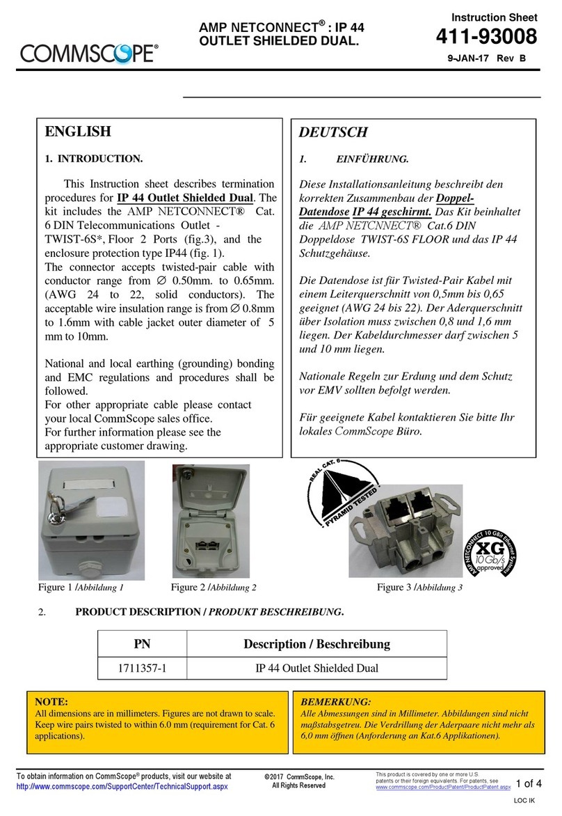
Undercarpet Power Splice Connector 553454-1 and
Power Tap Connector 553455-2 are designed to
electrically and mechanically connect two pieces of
undercarpet power cable. These connectors can be
used with cable sizes 12 AWG having 3 or 5
conductors.
Dimensions in this instruction sheet are in metric
units [with U.S. customary units in brackets].
Figures are not drawn to scale.
Reasons for reissue of this instruction sheet are
provided in Section 5, REVISION SUMMARY.
To obtain information on AMP NETCONNECT®
products, contact your local CommScope® account
representative, PartnerPRO™ Network Partner or
visit our website at www.commscope.com.
2. DESCRIPTION
The splice connector connects one conductor atthe
end of a cable to one conductor at the beginning of
another cable.
The tap connector connects one conductor of a tap
cable to one conductor of amain run cable.
3. INSTALLATION PROCEDURE
IMPORTANT:It is recommended that a qualified
electrician install undercarpet power splice and
power tap connectors.
To avoid personal injury, ALWAYS DISCONNECT
the electrical power before beginning work on any
circuit.
At each splice and tap connector location, use 3
power connectors for 3-conductor power cable and
5 power connectors for 5-conductor power cable.
3.1. Splice Connector
1. Align one cable end with the other cable end.
Trim both cables evenly across the ends allowing
a 3.18-mm [.125-in.] gap between them. Fold
back the top blue vinyl shield. See Figure 2.
2. Carefully separate the cable conductors along
the perforations for a length of 50.8 mm [2.0 in.].
3. Maintaining the gap between the two cables
(specified in Step 1), tape the cable ends with
standard electrical tape.
The electrical tape is used to keep the cable ends
from shifting during installation.
.
Figure 2
4. Ensure that the cable is clean by wiping it with
a dry, clean, soft cloth. DO NOT remove the
electrical tape.
5. Position a splice connector around the
appropriate conductor on each cable starting with
position 1 of the crimping order shown in
Figure 3. Then using Hand Tool 91392-1, crimp
each connector as follows.
NOTE
i
AMP NETCONNECT logo is a trademark of CommScope.
DANGER
STOP
NOTE
i
NOTE
i
3.18-mm
[.125-in.] Gap
Fold Back
Top Blue Vinyl Shield
Electrical
Tape
50.8 mm
[2.0 in.]
Installing Splice Connector to Undercarpet Power Cable
Splice Connector
553454-1
Tap Connector
553455-2
©2016 CommScope, Inc.
All Rights Reserved
This product is covered by one or more U.S.
patents or their foreign equivalents. For patents, see
www.commscope.com/ProductPatent/ProductPatent.aspx
408-3128
2of 3
Rev D
Refer to 408-10267, included with the tool, for
instructions on how to use the tool. It is
recommended not to use any other crimping
method.
a. Crimp one end of the splice connector onto
one end of the cable.
b. Crimp the other end of the splice connector
onto the other end of the cable.
c. Position and crimp the remaining splice
connectors following the crimping order shown
in Figure 3.
6. After crimping all of the splice connectors,
install Cable Insulator 556411-1 over all of the
splice connectors. Refer to 408-3218.
Cable Insulator 556411-1 (available separately) is
required for all splice connectors.
Figure 3
3.2. Tap Connector
1. Align the tap cable perpendicular to the main
run cable with a 3.18-mm [.125-in.] gap between
the cables. Fold back the top blue vinyl shield of
the tap cable. Cut and separate the top blue vinyl
only (approximately 457.2 mm [18 in.]). See
Figure 4. DO NOT cut the bottom blue vinyl
shield.
2. Carefully separate the main conductors and
tap conductors along the perforations for a length
of 152.4 mm [6.0 in.].
3. Ensure that the cable is clean by wiping it with
a dry, clean, soft cloth.
Figure 4
4. Position a tap connector around the
appropriate conductor on each cable starting with
position 1 of the crimping order shown in
Figure 5. Then, using Hand Tool 91392-1, crimp
the connectors as follows.
Refer to 408-10267, included with the tool, for
instructions on how to use the tool. It is
recommended not to use any other crimping
method.
a. Remove the cover paper from the tap
connector to expose the adhesive film.
b. Slide the tap connector around the
appropriate conductors.
c. With both cables lying flat on the floor, press
the tap connector firmly against the cable to
affix the adhesive.
d. Crimp one end of the tap connector onto one
end of the cable.
e. Crimp the other end of the tap connector
onto the other end of the cable.
f. Position and crimp the remaining tap
connectors following the crimping order shown
in Figure 5.
5. After crimping all of the tap connectors, install
Cable Insulator 556411-1 over all of the tap
connectors. Refer to 408-3218.
Cable Insulator 556411-1 (available separately) is
required for all tap connectors.
!
CAUTION
NOTE
i
1
2
3
4
5
Crimping Order for Splice Connectors
3
12
5-Conductor Cable
3-Conductor Cable
3.18-mm
[.125-in.]
Gap
Main Run Cable
Cut and Separate Top Blue Vinyl Shield
457.2 mm [18 in.]
(DO NOT Remove)
Tap
Cable
Fold Back
152.4 mm
[6.0 in.]
Top Blue
Vinyl
Shield
!
CAUTION
NOTE
i
Installing Tap Connector to Undercarpet Power Cable
408-3128
3of 3
Rev D
Figure 5
4. REPLACEMENT AND REPAIR
The splice connector and tap connector are not
repairable. DO NOT use any defective or damaged
connectors.
5. REVISION SUMMARY
Revisions to this instruction sheet include:
•Rebranded to CommScope.
Crimping Order for Tap Connectors
3
2
1
Cover Paper
Adhesive
Film
5-Conductor Cable
3-Conductor Cable
1
2
3
45
Tap
Connector
VERSA-TRAK is a trademark.

This manual suits for next models

1

Other CommScope Cables And Connectors manuals

CommScope FIST-RSKG-16 User manual

CommScope

CommScope FIST-RSKG-16 User manual

CommScope FOSC-450D User manual

CommScope

CommScope FOSC-450D User manual

CommScope FIST-RSKG-1 User manual

CommScope

CommScope FIST-RSKG-1 User manual

CommScope 760230938 User manual

CommScope

CommScope 760230938 User manual

CommScope HELIAX MFJS6UDHNA00 User manual

CommScope

CommScope HELIAX MFJS6UDHNA00 User manual

CommScope OSP-CLPFEC-LG User manual

CommScope

CommScope OSP-CLPFEC-LG User manual

CommScope SYSTIMAX 360 iPatch 360-iP-G2-1U-LC-FX User manual

CommScope

CommScope SYSTIMAX 360 iPatch 360-iP-G2-1U-LC-FX User manual

CommScope SCIL-B User manual

CommScope

CommScope SCIL-B User manual

CommScope HELIAX FiberFeed HTC1006 Series Instruction sheet

CommScope

CommScope HELIAX FiberFeed HTC1006 Series Instruction sheet

CommScope FOSC 450 A User manual

CommScope

CommScope FOSC 450 A User manual

CommScope FOSC-400BG User manual

CommScope

CommScope FOSC-400BG User manual

CommScope PICABOND 60944-6 User manual

CommScope

CommScope PICABOND 60944-6 User manual

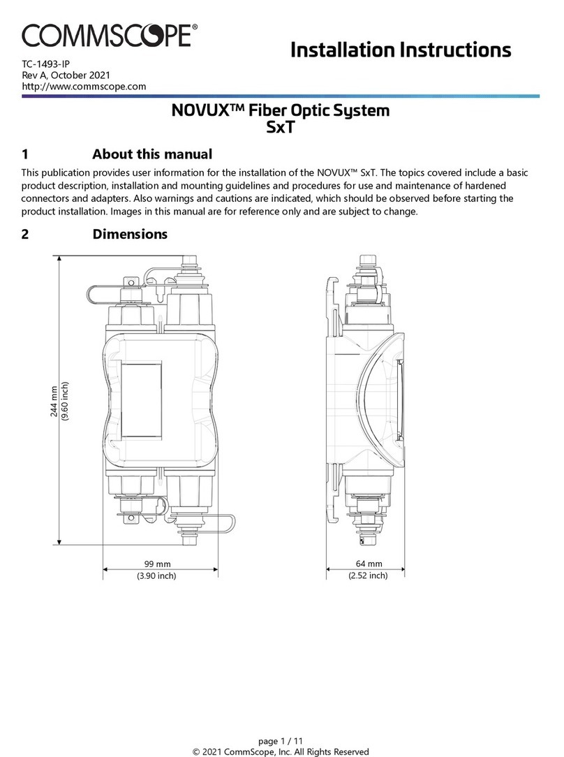
CommScope NOVUX SXT User manual

CommScope

CommScope NOVUX SXT User manual

CommScope BUDI-S User manual

CommScope

CommScope BUDI-S User manual

CommScope TDUX-35 User manual

CommScope

CommScope TDUX-35 User manual

CommScope LC User manual

CommScope

CommScope LC User manual

CommScope AMP NETCONNECT SL Series User manual

CommScope

CommScope AMP NETCONNECT SL Series User manual

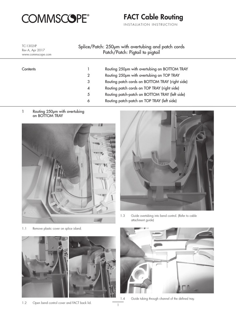
CommScope FACT User manual

CommScope

CommScope FACT User manual

CommScope HELIAX FiberFeed FDH1206-12M50 Series Instruction sheet

CommScope

CommScope HELIAX FiberFeed FDH1206-12M50 Series Instruction sheet

CommScope FOSC450 C User manual

CommScope

CommScope FOSC450 C User manual

CommScope SYSTIMAX 360 iPatch... User manual

CommScope

CommScope SYSTIMAX 360 iPatch... User manual

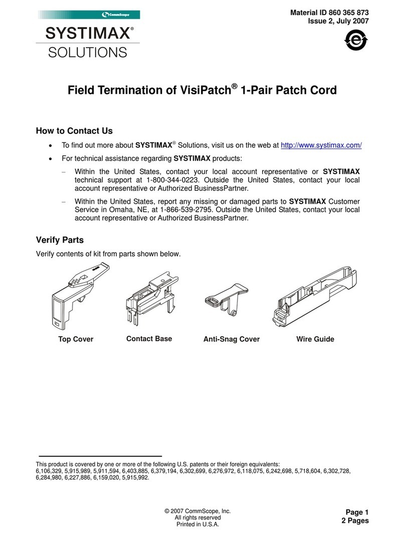
CommScope SYSTIMAX VisiPatch CPC5562 User manual

CommScope

CommScope SYSTIMAX VisiPatch CPC5562 User manual

CommScope HELIAX FiberFeed HFE810 Series Instruction sheet

CommScope

CommScope HELIAX FiberFeed HFE810 Series Instruction sheet

CommScope HELIAX FiberFeed HFA208 Series Instruction sheet

CommScope

CommScope HELIAX FiberFeed HFA208 Series Instruction sheet

Popular Cables And Connectors manuals by other brands

DAZE MODE 3 User and installation manual

DAZE

DAZE MODE 3 User and installation manual

Hirose EnerBee DF60 Series manual

Hirose

Hirose EnerBee DF60 Series manual

opticis M1-1000 user manual

opticis

opticis M1-1000 user manual

NTI VOPEX-C5VA/C5V-x(C) Installation and operation manual

NTI

NTI VOPEX-C5VA/C5V-x(C) Installation and operation manual

Renesas Extension Cable for FLX160 M3T-F160-EXTC user manual

Renesas

Renesas Extension Cable for FLX160 M3T-F160-EXTC user manual

Street Guardian SGDCHW user manual

Street Guardian

Street Guardian SGDCHW user manual

Linetek 2.0 HDMI Splitter 1x2 user manual

Linetek

Linetek 2.0 HDMI Splitter 1x2 user manual

nvent Raychem CCON20-100-PI Series Installation and operating instructions

nvent

nvent Raychem CCON20-100-PI Series Installation and operating instructions

Unicol PSK manual

Unicol

Unicol PSK manual

Philips SWV2120NB Specifications

Philips

Philips SWV2120NB Specifications

Staubli MC4-Evo 2 PV-K/SPL-Y Installation and operation manual

Staubli

Staubli MC4-Evo 2 PV-K/SPL-Y Installation and operation manual

ITRON iSPE12-50 operating instructions

ITRON

ITRON iSPE12-50 operating instructions

Exsys EX-1311-2F manual

Exsys

Exsys EX-1311-2F manual

TRENDnet TK-C15 - DATA SHEETS Other

TRENDnet

TRENDnet TK-C15 - DATA SHEETS Other

Philips SWV2209 Specifications

Philips

Philips SWV2209 Specifications

Danfoss 130B9975 installation instructions

Danfoss

Danfoss 130B9975 installation instructions

gofanco DPMSTHub user manual

gofanco

gofanco DPMSTHub user manual

STODIA 9926 operating manual

STODIA

STODIA 9926 operating manual

manuals.online logo
manuals.online logoBrands
  • About & Mission
  • Contact us
  • Privacy Policy
  • Terms and Conditions

Copyright 2025 Manuals.Online. All Rights Reserved.