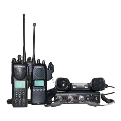
COMMUNICATIONS-APPLIED TECHNOLOGY ICRI-E Manual

COMMUNICATIONS-APPLIED TECHNOLOGY
11250-14 Roger Bacon Drive Reston, VA 20190
Voice: 800-229-3925 Support: Techsupport@c-at.com
Revision I
10/2010
Setup and Operating Procedures
ICRI-E
Incident Commanders’ Radio Interface™
A Rapidly Deployable, Radio Interoperability Solution
Waterproof, Gross Decon-able
MANUFACTURED BY
COMMUNICATIONS-APPLIED TECHNOLOGY CO., INC.
RESTON, VA.
CAGE CODE: 0EEY2
http:// www.c-at.com
If you have any questions, please contact:
C-AT TECHNICAL SUPPORT at 800-229-3925 (voice) , 703-471-4428 (fax), or

- 2 -
TABLE OF CONTENTS:
THEORY OF OPERATION ....................................................................................................... 3
PRE-OPERATIONAL ACTIVITIES......................................................................................... 4
SET-UP AND USE INSTRUCTIONS ........................................................................................ 5
FIGURE 2: ICRI WITH RADIOS.............................................................................................. 5
OPERATION OF THE ICRI............................................................................................................... 6
SETTING UP THE ICRI FOR USE...................................................................................................... 6
INTERNALPANEL:................................................................................................................... 7
EXTERNALPELICAN CASE:................................................................................................... 8
ICRI POWER.............................................................................................................................. 11
TO POWER THE ICRI8―AA‖ BATTERIES: ................................................................................... 11
USE AN ALTERNATE DC SOURCE TO POWER THE ICRI................................................................ 12
USE AN AC SOURCE TO POWER THE ICRI. .................................................................................. 13
LAND MOBILE INTERFACE................................................................................................. 14
CONNECT INTERFACE CABLES..................................................................................................... 14
SET THE RADIO TO TRANSMIT THROUGH THE ICRI...................................................................... 15
5.0 OPTIONAL SATPHONE, LAND-LINE TELEPHONE, CELLULAR PHONE
INTERFACE............................................................................................................................... 16
ICRI PHONE LINK IN RJ-22 CONNECTION .................................................................................... 16
CELLULAR TELEPHONE LINK ....................................................................................................... 16
NEXTELTM PHONE IN DIRECTCONNECTTM MODE......................................................................... 17
THE LOCAL HANDSET.................................................................................................................. 17
APPENDIX A: 250’ RADIO EXTENSION CABLE REEL................................................... 18
Set-up of the Cable-Reel......................................................................................................... 19
APPENDIX B: CONNECTOR PIN-OUT DATA.................................................................... 23
APPENDIX C: ICRI APPLICATIONS.................................................................................... 24
APPENDIX D: ICRI CHASSIS................................................................................................. 26
APPENDIX E: PART NUMBERS FOR ICRI-E ACCESSORIES AND CABLES............. 27
APPENDIX F: ICRI BOARD ADJUSTMENTS..................................................................... 28
APPENDIX G: FCC 15.21 INFORMATION TO USER:....................................................... 30

- 3 -
Theory of Operation
In simplest terms, the ICRI performs two primary functions:
Distributes audio received from one two-wayradioto otherradios, telephoneorrecordingdevice
connected to the ICRI.
Utilizes this same incoming audio to ―key‖ the other radios connected to the ICRI.
This configuration of the ICRI is designed to be quicklyset-up, and to operate for extended periods
without additional power sources or specialized support equipment.
This ICRI interfaces through the interconnect cables to link radios and telephones. Commercial
radios---both portable and mobile radios--- can be rapidly linked together to form radio
communications ―nets‖ of radios that could not otherwise communicate with one another. Military
radios, and satellite ―phone‖ and voice-over-IP devices can be linked to the 2-wayradios to extend
the command and control capabilities of the personnel on-scene and at remote locations.
The ICRI will operate for at least 24 hours, with 8 ―AA alkaline batteries (somewhat less in cold
weather). The ICRI can also be powered byan external batterypack, a vehicle-supplied or otherDC
source, or AC.
Two, three, four, five radios can be linked together through the ICRI. Unencrypted radios can be
linked in one talk group while encrypted can be linked in thesecondtalkgroup. Talk groupselection
is controlled by the switches about each radio ―port‖.
Two ICRIs can be rapidly linked together without hand tool and/or adjustments. An interconnect
cable may be part of this kit or is readily available.
A 250’ extension cable for radio interface may be supplied with this kit. The extension cable
permits a radio to be placed at this distance from the ICRI. This may useful when connecting to a
satellite antenna/radio or when a team enters a structure/tunnel. Multiple extension cables can be
connected for even greater distances (tested up to 5000’).
The ICRI does not discriminate or evaluate the incomingaudio so that delaysarenot insertedinto the
audio transfer or ―keying‖ processes. Radios, telephones and/or recording devices connected to the
ICRI are provided with the incoming audio essentially in real-time (an initial delay at keying to
preserve the first syllables of incoming audio as the transmitters[including widearea, repeater-based
―trunked‖ radio systems] are keyed up).
An ICRI contains up to six circuits that key the radios connected to the ICRI; these circuits are
commonly referred to as ―VOX‖ or ―voice-activated switches.‖ The ICRI uses these circuits to
perform other controlling functions as well. Only the VOX directlyconnectedto theincomingaudio
is used to keyeach of the other radios simultaneously(all other are temporarilydisabled, preventing
a second ―voice‖ from causing a disruption in initial voice being distributed).
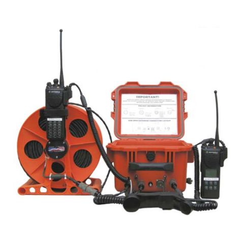
- 4 -
Pre-Operational Activities
Some pre-planning is necessary to ready the ICRI for use. The following should be accounted for
before placing the ICRI on-line:
1.0 Predetermine what the power source will be for the ICRIand verifythat the cable or battery
pack is available.
2.0 Predetermine what brand and model of radios will be connected to the ICRI and that an
―interconnect‖ cable for each radio is available.
3.0 Advise agencies that they will need to supply a ―spare‖ radio, for the radio interoperability,
that the radio supplied must be known to operate properlyand have at least onefullycharged
battery.
The ICRI can be powered by the internal batteries or another DC source up to 31 VDC. The LEDs
on the ICRI provide information battery status, in particular, a reliable indication of a low voltage
condition. Note that if eight “AA batteries are used, the ICRI will continue operate to nominally for
at least 2 hours after the “OK” LED is extinguished and the “LOW” LED has lit and then
extinguished (batteries will provide a reduced duty cycledueto low quality, poor storageconditions
before use, and/or low temperature during use).
Among the possible power sources that can be used to power the ICRI are:
NATO Slang vehicle power
115VAC (with an external adapter)
BA590 ―military‖
Commercial dry-cell battery (12V or greater)
C-AT internal 12 volt battery insert (uses 8 ―AA‖ batteries)
The ICRI’s internal regulated power supplyis reverse polarityprotected, but it is important to check
polarity of DC supplies before connecting them to the ICRI. Note that the ICRI power input
connector information appears on the inside cover of the ICRI.

- 5 -
Set-up and Use Instructions
The ICRI-E is internallyhoused in the Pelican case;thereforethis version does not providea location
for storing cables and radios inside the unit. However, the ―AA‖ batteries are stored and operational
from within the unit and accessible from the front panel.
Abbreviated set-up instructions are printed onto the top cover of the ICRI assembly. Connector
information for radio, telephone, and power interconnect cables is printed on the insidecoverofthe
case. Refer to Appendices B and C.
FIGURE 1: ICRI CASE (INSIDE)
FIGURE 2: ICRI WITH RADIOS

- 6 -
Operation of the ICRI
Setting up the ICRI for use.
Verify ―fresh‖ AA batteries are installed or connect a power source to the ICRI.
Turn on the ICRI so that power up and input voltage can be verified. If you need to useaDCsource
voltage between 6.5 and 7.4 volts, then neither the OK nor the LOW voltage LEDs will belit,but the
ICRI will be working.
Set the radios to the assigned interoperability channels, verify the radios transmit and receive
function with another radio. Then connect the radio interface cables to the radios and the ICRI. All
five ICRIradio interface connections are electricallyidentical, so it is not important which jacks are
used during ICRI operation.
Select the talk-group the radio will be assigned to and place the switch above the associated port in
the desired position.
NOTE: The centerposition of the switch placesany item connected with theassociated port into a
“NO CONNECTION” condition without physically disconnecting the device from the ICRI.
Turn the radios on; initiallyplace the radio volumecontrols at a mid-position between fullycounter-
clockwise and fully clockwise. As a radio connected to the ICRI receives voice for a remote radio
user for the first time, adjust the radio’s volume control so that the associated LED flickers as words
are spoken. The LED should not remain on continuously as the voice is received.
Connect the telephone and handset, if they will be used. Select the talk-group the telephone and/or
handset will be associated with. Turn on the telephone.
NOTE: For initial setup and troubleshooting purposes, C-AT recommends the use of the local
handset or headset.

- 7 -
INTERNAL PANEL:
FIGURE 3: INTERNAL PANEL
ACTIVE VOX (VOICE ACTIVATED CIRCUIT) LED INDICATOR: A
Each LED is associated with a voice communications port (radio, telephone). When the port
receives audio from the radio or otherconnected device, theLED will lightasthe audiois received at
the ICRIcircuitry. The LED should light as each word is spoken. To adjust the level of theincoming
audio, adjust the volume control of the device connected to the ICRI.
TALK GROUP SWITCH: B
The talk group switches determine which communications devices will be connected/interoperate
each other. Only the radios, telephone, or handset connected to a specific talk group will hear or be
able to transmit audio to the other individuals connected to that talk group. The switch corresponds
to the interface jacks below it. Radios/interfaces DO NOT need to be turned off or disconnected to
switch talk groups.
UP: Talk Group 1
CENTER: Not connected to either talk group
DOWN: Talk Group 2
ON-OFF SWITCH: C
This switch is used to turn the ICRI ON and OFF; there is no delay between ―POWER ON‖ and
radio link.

- 8 -
OK/ LOW IMPUT VOLTAGE LEDs: D
These two LEDs indicate the following:
The Green LED indicates the input voltage 8.6 or greater. If batterypower option is used,the
ICRI will have approximately 24 hours of run time at full duty cycle.
The red LED indicates the input voltage is 7.5 to 8.5 volts. Once this light is illuminated the
ICRI will have approximately 2 hours of run time.
Note: If neither LED is lit, the ICRI will operate on voltage as low as 6.5V. Maximum input
voltage is 31VDC
BATTERY COMPARTMENT (See Section 3.0): E
EXTERNAL PELICAN CASE:
FIGURE 4: EXTERNAL ICRI
TALK GROUP SWITCH (HANDSET/HEADSET): F
The talk group switches determine which communications devices will be connected/interoperate
each other. Only the radios, telephone, or handset connected to a specific talk group will hear or be
able to transmit audio to the other individuals connected to that talk group. The switch corresponds
to the interface jacks below it. Radios/interfaces DO NOT need to be turned off or disconnected to
switch talk groups.
LEFT: Talk Group 1
CENTER: Not connected to either talk group
RIGHT: Talk Group 2
VOLUME ADJUSTMENT (HANDSET/HEADSET) G
Volume knob only adjusts the volume output level at a handset or headset connected to the ICRIat
―Handset Interface‖ jack. To adjust the volume of the radios, use the volume adjustment on the
individual radios.

- 9 -
HANDSET/HEADSET JACK H
This 5 pin U183 connector supports the H250/H350 handset
Pinout:
1- Ground
2- Mic
3- PTT
4- Audio Hi+
5- Audio Hi-

- 10 -
RADIO JACK (1 thru 5) J
The five radio interface jacks on this unit are a 5-pin, U183 locking jacks. All radio jacks are
compatible with a military and commercial radios and Nextel™Direct Connect™phones (except
Blackberry and i60/i90 models)
Pinout:
1- Ground
2- Audio from radio
3- Audio to radio
4- Motorola® Saber/AstroSaber P-T-T enable
5- P-T-T Enable (except Motorola Saber and Motorola P Series Radios)
TELEPHONE /ACOUSTIC COUPLER JACK: K
This interface jack can be used to connect the ICRI to a satellite telephone, land-line or cellular
phone. The 8-pin locking-type jack supports the connection of the ICRI to a telephone through the
acoustic coupler (PN 1790.650) or the 2.5mm jack on a cell phone (PN 179.0672)
Pinout:
A- Audio TO telephone (acoustic coupler)
B- Audio FROM telephone (acoustic coupler)
C- Audio TO telephone (acoustic coupler)
D- Audio FROM telephone (acoustic coupler)
E- Ground
F- Required jumper
G- Audio TO telephone (2.5mm plug)
H- Audio FROM telephone (2.5mm plug)
POWER (DC INPUT) JACK: L
Power jack is used to connect ICRI battery pack, alternative DC power source (vehicle) or AC
power. The Power jack is an 2-pin locking jack. Align arrow at top of ICRI to properly insert the
power jack. To remove, unscrew the connector and then gently pull on the connector at the base.
Pinout:
1 –+7 to +20 VDC
2 –Ground

- 11 -
ICRI Power
The ICRI-E can be powered by 8 ―AA‖ batteries housed on the inside cover of the unit, external DC
or AC power.
To power the ICRI 8 “AA” batteries:
FIGURE 5: INTERNAL BATTERY HOUSING
Open the Pelican case.
Loosen the two thumbscrews (E) holding the batterycover plate on theupperright hand corner ofthe
ICRI and remove the plate.
Remove the old batteries and discard properly.
Replace the 8 "AA‖ alkaline batteries, observing the polarity markings within the tray.
Replace the battery cover and tighten down the thumbscrews.
Note: No tools are required to loosen or tighten these thumbscrews. Finger pressure is enough to
tighten or release the plate.
The battery housing is comprised of two parts; the cover and an internal tray.
NO TOOLS ARE NEEDED TO REMOVE THE cover AND REPLACE THE BATTERIES.

- 12 -
Use an alternate DC source to power the ICRI.
When powering the ICRI with an alternate DC source or through vehicle power source, connect the
in-line jack to the in-line plug. Note that the pins are polarized and the connection is made so that
the jack’s locking ―blades‖ slide between the ―blades‖ on the plug and the body of the plug.
Connect the other end to the vehicle cigarette lighter. If using the NATO slang connector into the
vehicle power source.
Connect the adapter’s plug to the jack labeled DC INPUT. Tighten locking screw, it is important
that the connector be firmly seated against the radio so that good electrical contact is made.
Note: Align the plug’s “key” with the jack’s “keyway” before attempting to insert the plug.
To release, loosen the locking screw and gently remove the connector.
Note: DO NOT remove the power cable by pulling from the cable.
FIGURE 6: NATO SLANG POWER ADAPTOR

- 13 -
Use an AC source to power the ICRI.
This power supply consists of two parts: the three-prong AC power cable and an AC to DC
converter with an interconnect cable.
Note: The AC supply must not be used where the cables or converter can become wet.
Connect the power cord to the converter and to the DC source (110-120V, 60Hz).
Connect the adapter’s plug to the jack labeled DC INPUT. Tighten locking screw, it is important
that the connector be firmly seated against the radio so that good electrical contact is made.
Note: Align the plug’s “key” with the jack’s “keyway” before attempting to insert the plug.
To release, loosen the locking screw and gently remove the connector.
Note: DO NOT remove the power cable by pulling from the cable.
FIGURE 7: AC POWER ADAPTOR, CHECK +/-
FIGURE 8: AC POWER SUPPLY, VIEW 2

- 14 -
Land Mobile Interface
NOTE: Radio interconnect cables are generally specific to a radio brandandmodel, although some
manufacturers use the sameconnector for several radiomodels. InterconnectcablesprovidedbyC-
AT have a seven digit part number label on the cable.
Connect Interface cables
Install the radio-end of the ICRI interconnect cable onto the radio, as you would install any radio
accessory (i.e.: a shoulder speaker / microphone).
Tightening any locking screws is optional; but it is important that the connector be firmly seated
against the radio so that good electrical contact is made.
Attach the other end of the cable to any of the LAND MOBILE RADIO INTERFACE jacks,
labeled 1, 2, 3, 4 and 5.
NOTE: The plug on the cable and the jack are “keyed”. Be sure to align the key before inserting
the plug on to the connector or the connection may be damaged
FIGURE 9: ICRI RADIO TALK GROUP
SELECTOR
FIGURE 10: ICRI CONNECTORS AND HANDSET
TALK GROUP SELECTOR
FIGURE 11: RADIO WITH ICRI CABLE
ATTACHED
To connect interface cable to ICRI, align flat surface of connector to red dot on the selected ICRI
port. Push the cable onto the jack and turn clockwise until cable locks in place.
To remove the connector, push the interface cable side in towards the ICRI, and turn
counterclockwise until the cable releases. Then pull the connector straight out of the jack. Hold the
barrel of the connector rather than the cable.

- 15 -
Set the radio to transmit through the ICRI
Set the audio level on each connected radios to mid position.
NOTE: Radio interconnect cables are generally specific to a radio brand and model, although
Set the radio to the desired channel.
Set the talk group switch
Up: Talk Group One
Down: Talk Group Two
Center: no Talk Group connection (mute)
Because the ICRI is connected to the radio via the speaker jack, the audio path on the attached radio
is disrupted. You will be unable to hear or speak through that radio. If you can hear or talk through
the radio, the cable may not be properly attached to your radio.
The LED directlyabove the radio will light as audio is transmitted from the radio through the ICRI.
If the users are having difficultytransmittingbetweendisparate radios/channels,usethelocal handset
to test the audio.
Connect the local handset to the jack on the front of the ICRI labeled, HANDSET. The jack on the
handset is similar to those provided for the radio cables. The handset connector contains more pins
and is designed to be the only cable used in the HANDSET jack.
After connecting the handset, set the volume knob to mid position, set the talk group switches
(located directlyabove the corresponding radio connection) to the same position as the other radios
being used.
Depress the P-T-T bar on the inside of the handset to speak. The LEDs directlyabovetheradio ports
in use should light. If they remain solidly lit, turn down the
volume. If the LEDs do not light:
Slowly increase the volume settings.
Check to make sure the cable is solidly connected to the
radio and the ICRI.
Make certain the radio has a charged battery.
Check if the radio can function normallywith a speakermic
attached.
FIGURE 12: HANDSET INTERFACE JACK

- 16 -
5.0 Optional SATPHONE, Land-line Telephone, Cellular Phone Interface
NOTE: If a land-line, cellular telephone or satellite telephone will be linked through the ICRIto
the2-way radios, the “acoustic coupler” (part number 179.0617) interconnect cable can beused.
If a cellular telephone with a 2.5mm “headset” jack will be linked through the ICRI to the 2-way
radios, an interconnect cable with a 2.5mm plug (part number 179.0618) can be used.
ICRI phone link in RJ-22 connection
The ICRIcan be configured with an optional RJ-10 jack adapter that attaches to the 8-pin jack on the
outside of the ICRI-E. This jack will provide the user the ability connect a standard telephone
handset without using the standard telephone port on the front of the ICRI.
To use the RJ-22 jack adapter with a land-line, on your standard phone, disconnect the cable from
the handset of the phone while leaving it connected to the base. Plug the cabledirectlyintothe RJ-22
jack on the side of the ICRI.
NOTE: The ICRI must be open to use the RJ-22 jack
FIGURE 13: TELEPHONE INTERFACE ADAPTER JACK
Cellular telephone link
When connectingto a cellular telephone connect the small, single shaft connector totheheadsetjack
on the cellular telephone. Be sure it is firmly seated in the telephone.
Plug into ICRI at jack labeled ―Telephone Interface.
NOTE: The plug on the cable and the jack are “keyed”. Be sure to align the key before inserting
the plug on to the connector or the connection may be damaged.
Set telephone’s earphone audio to a mid-level setting following the telephone’s instructions.
After the interconnect cable from the repeater is connected to the telephone handset, a dial tone
should be heard in the earphones of the portable radio and in the earpiece of the "local" handset.
Dial the telephone number of another telephone.
Dial the desired telephone number.
When the called partyanswers, use the portable radio's throat mic or a headset andbegin toconverse
with called party.

- 17 -
NOTE: Third party needs to be aware of basic radio etiquette and delays for radio keying
Otherwise, they will monopolize the radio channel or will not be properly understoodbythe radio
users.
To remove the connector forcable storage, push inward on the lockingring and turnthe ringcounter
clockwise to release the locking mechanism. Then pull the connector straight out of the jack. Hold
the chrome barrel of the connector rather than the cable.
NextelTM phone in DirectConnectTM mode
When connecting a NextelTM connect the phone as you would an L-M-R.
Install the radio-end of the ICRI interconnect cable onto the accessory jack at the bottom of the
phone, as you would install any accessory (i.e.: a shoulder speaker / microphone)
Attach the other end of the cable to any of the LAND MOBILE RADIO INTERFACE jacks.
NOTE: The Nextel speaker and mic will be disabled while the phone is connected to the ICRI.
The local handset
This handset can be used as a local incident command radio or a troubleshooting device. Up to 250’
of cable maybe added to the cable length. Then handset maybe replace with a C-AT provided
headset.
The handset microphone is enabled when the push-to-talk bar in the center of the handset is
depressed and held down.
The audio level to the handset speaker can be adjusted by the rotating the volume knob above the
jack. Counterclockwise decreases the audio level, and clockwise increases the listening level.

- 18 -
APPENDIX A: 250’ Radio Extension Cable Reel
Positioning one or more of the radios, to be connected to the ICRI at a distance greater than
the length of the interface cable may be desirable for one of several operational reasons:
1. The personnel associated with a radio will be located inside a building for which there is
poor RF coverage from the ICRI’s location.
2. The personnel associated with a radio will be located inside a tunnel or other below grade
area for which there is poor RF coverage from the ICRI’s location.
3. Radios operatingin veryclose proximityto one another, negativelyaffect the performanceof
other another, such as receiver desensing.
The personnel—equipped with compatible radios—in the same generallocationof the reel-mounted
radio, will be able to communicate with those operating radios or the handset also connected to the
ICRI.
The extension cable is inserted between the ICRI and the radio interconnects cable that is usually
connected directly to one of the radio ports on the ICRI front panel.
NOTE: Multiple reels of cable can be linked togetherforrequirementof greaterdistancethan250
feet. There will be no degradation of the communications link for up to 5000 feet ofcable, BUT it
is important to note that if the cable is run near a source of high electrical energy, “noise” from
such a device can be expectedtobe induced into thecable and reduce---possiblysignificantly---the
quality of the communications.
It is strongly recommended that the radio link be tested before the personnel enter the area of poor
RF propagation, so that any defects with the cable or the connections will be noted before a safety
issue arises--due to a lack of radio communications.
Figure 14: EXTENSION CABLE
Figure 15: CABLE REEL CONNECTOR

- 19 -
Set-up of the cable-reel
Equipment required: ICRI, cable-reel, radio interface cablefor radio to be placed intheareaofpoor
RF coverage.
1. Connect the cableend thatexits from the sideof thereel to the radio interface cable. Be sure
to align the key-way and secure the connectors together.
2. Connect the unspooled cable to a radio port on the ICRI. Be sure to align the key-way and
secure the connectors together.
3. Place the radio on the right angle support and secure it in-place with the Velcro™strap.
NOTE: If the cable will be used to place a radio in a stairwell, or on a building roof, hill or tree
top to enhance the operating range of the radio, then it may be preferable to have the cable reel
located beside the ICRI and the radio connected to the unspooled end of the cable. In this case
reversal cables are needed.
Set-up of the Cable-Reel
Equipment required: ICRI, cable-reel, radio interface cablefor radio to beplaced inthearea ofpoor
RF coverage.
1. Place the radio on the right angle support and secure it in-place with the Velcro™strap.
2. Connect the cable end that exits from the side of the reel to the radio interface cable. Besure
to align the flat surface ofconnector to red dot on the selected ICRI port. Push the cableonto
the jack and turn clockwise until cable locks in place.
3. Connect the unspooled cable to a radio port on the ICRI. Be sure to align the keyway and
secure the connectors together with the locking ring on the male connector.
4. Unreel the desired length of cable—this may be all the cable if the distance is unknown.
5. If needed, connect additional cable reels between the ICRIand the first reel (up to eight fora
total distance of 5000’ feet).
NOTE: If the cable will be used to place a radio in a stairwell, or on a building roof, hill or tree
top to enhance the operating range of the radio, then it may be preferable to have the cable reel
located beside the ICRI and the radio connected to the unspooled end of the cable. In this case,
reversal cables are needed.

- 20 -
Set-up of the cable-reel with reversal cables:
Attach one end of cable ―A‖ to the male connector located near the center hub on the reel. Attach the
other end of cable ―A‖ to an ICRI radio port.
A
Attach one end of adapter ―B‖ to the female connector at the ―free‖ end of the cable. Attach the
other end of adapter ―B‖ to a radio interface cable.
B
With this configuration, the cable reel will remain with the ICRI unit and the radio would travel to
the incident site or remote location for better operating range of the radio.
FIGURE 16: REVERSAL CABLES
Table of contents
Other COMMUNICATIONS-APPLIED TECHNOLOGY Conference System manuals

COMMUNICATIONS-APPLIED TECHNOLOGY
COMMUNICATIONS-APPLIED TECHNOLOGY ICRI/2PE Manual

COMMUNICATIONS-APPLIED TECHNOLOGY
COMMUNICATIONS-APPLIED TECHNOLOGY ICRI/2P Manual

COMMUNICATIONS-APPLIED TECHNOLOGY
COMMUNICATIONS-APPLIED TECHNOLOGY ICRI/2PE Manual

COMMUNICATIONS-APPLIED TECHNOLOGY
COMMUNICATIONS-APPLIED TECHNOLOGY ICRI-WFM Manual