COMMUNICATIONS-APPLIED TECHNOLOGY ICRI/2P Manual

Revision AM.2
2/2011
Setup and Operating Procedures
ICRI/2P™
As configured for the Federal Air Marshals
Under Order # HSTS07-08-F-00273,
dated 9/15/2008
Incident Commanders’ Radio Interface™
A Rapidly Deployable, Radio Interoperability Solution for Public Safety Personnel
MANUFACTURED BY
COMMUNICATIONS-APPLIED TECHNOLOGY CO., INC.
RESTON, VA., USA
CAGE CODE: 0EEY2
http://www.c-at.com
If you have any questions, please contact:
C-AT TECHNICAL SUPPORT at 800-229-3925 x23 (voice) 703-471-4428 (fax), or

TABLE OF CONTENTS:
THEORY OF OPERATION ....................................................................................................... 3
PRE-OPERATIONAL ACTIVITIES......................................................................................... 4
INITIAL SETUP........................................................................................................................... 6
PELICAN CASE ICRI STORAGE ............................................................................................ 7
CONTROLS AND INDICATORS.............................................................................................. 9
FRONT PANEL............................................................................................................................... 9
REAR PANEL............................................................................................................................... 11
ICRI POWER.............................................................................................................................. 12
POWERING THE ICRIWITH INTERNAL LITHIUM ION BATTERY:.................................................... 12
POWER THE ICRIWITH THE OPTIONAL C-AT BATTERY PACK (8 “AA” CELLS) ........................... 13
POWER THE ICRI-2P WITH CIGARETTE LIGHTER OR ALLIGATOR CLIPS CABLE (P/N 179.0730).... 14
PORTABLE RADIO INTERFACE.......................................................................................... 15
CONNECTING THE PORTABLE RADIO............................................................................................ 15
OPERATING THE PORTABLE RADIO AFTER CABLE CONNECTION................................................... 17
USING A NEXTEL™PHONE IN DIRECT CONNECT™MODE........................................................... 17
SETTING RADIOS TO “BRIDGE”THROUGH THE ICRI-2P............................................................... 18
TROUBLESHOOTING RADIO SETUP............................................................................................... 18
LAND-LINE TELEPHONE, CELLULAR PHONE INTERFACE...................................... 19
CONNECTING A LAND LINE TELEPHONE TO THE ICRI-2P....................................................... 19
CONNECTING A CELLULAR TELEPHONE TO THE ICRI-2P....................................................... 20
THE LOCAL HANDSET .......................................................................................................... 21
USING THE HANDSET................................................................................................................. 21
ADJUSTING THE VOLUME.......................................................................................................... 21
ICRI TO ICRI LINK.................................................................................................................. 22
ICRI UNIT IDENTIFIER.......................................................................................................... 23
APPENDIX A: INTERFACE CAPABILITIES DIAGRAM FOR FAM ICRI-2P............... 24
APPENDIX B: CONNECTOR PIN-OUT DATA.................................................................... 25
APPENDIX C: ICRI-2P COVER INSTRUCTIONS (FAM CONFIGURATION).............. 26
APPENDIX D: ICRI BOARD ADJUSTMENTS..................................................................... 27
APPENDIX E: SOME INTEROPERABILITY DOS AND DON’TS ................................... 29
APPENDIX F: FCC PART 15.21 INFORMATION TO USER:............................................ 30
- 3 -
Theory of Operation
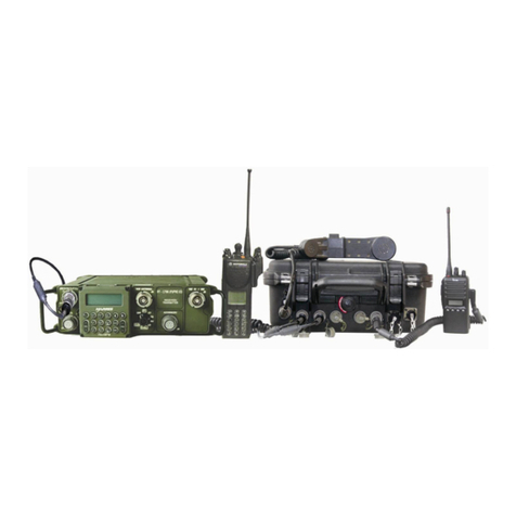
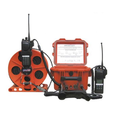
The “2P” can provide a communications bridge, or link, between two public safety agencies with
otherwise incompatible radios; can quickly establish the link as a tactical situation rapidly unfolds;
and requires minimal resources to enable it initially, or to maintain its operation over many hours.
The 2P will remain fully operational for 30+ hours powered byan external “AA” battery pack (8 “AA
alkaline batteries), 10+ hours powered by the internal, rechargeable battery, and indefinitely when
powered by an AC source.
The 2P performs two primary functions:
Distributes the audio received from a two-way radio, or telephone, to a second radio also
connected to the 2P.
Utilizes this same incoming audio to “key” the other communicationsdevicesconnectedtothe
ICRI. The “radios”can be hand-held portables, vehicleor consoleradios, SPRINT/NEXTEL
“Direct Connect” phones or a combination. Land-line telephones, cell phones, STU, STE or
satellite phones can also be connected to the ICRI.
The ICRI-2P circuitry does not attempt to modify or digitally process the incoming audio, so that
unnecessarydelays are not inserted into the audio transfer or “keying” processes. Radios, telephones
and/or recording devices connected to the ICRI are provided with the incoming audio, essentially in
real-time. An audio “buffer” preserves the first syllables of incoming audio processed through
“trunking” radio systems.
This version of the ICRI contains 2 circuits that key the radios connected to the ICRI; these circuits
are commonly referred to as “VOX” or “voice-activated switches.” Only the VOX directlyconnected
to the incoming audio is usedto keyeach of the other radios simultaneously(all othersaretemporarily
disabled, to prevent a second “voice” from causing a disruption of communication).The ICRI uses
these circuits to perform other controlling functions as well.

- 4 -
Pre-Operational Activities
Some pre-planning is necessary to ready the ICRI for rapid deployment. The following should be
accounted for before placing the ICRI on-line:
1. Determine what the power source will be for the ICRI. Verify that the internal battery is
charged or that one of the external power source option are available*.
2. Determine what brand and model of radios will be connected to the ICRI and that an
“interface” cable for each radio is available.
3. If radios are not maintained with the ICRI, advise participating agencies that theywill need to
supply a “spare” radio, for the radio interoperability.
4. Verifythat the radios are known to operate properlyand have at least one fullycharged battery
or other reliable power source.
*Among the power sources that can be used to power the ICRI are:
12 volt vehicle battery
Vehicle cigarette lighter
115v AC (with an external adapter)
BA590 “military”
Commercial dry-cell or other battery(7.2V up to20V DC, minimum 10.5V to charge
internal battery pack)
C-AT 12 volt battery pack (uses 8 “AA” batteries)
The ICRI’s internal regulated power supply is reverse polarity protected, but it is important to check
polarity of DC supplies before connecting them to the ICRI.

- 5 -
Interoperability DOs and DON’Ts
These simple “universal” rules will help to ensure that the part of communications interoperability
will work properly.
1. Verifythat only one interoperability bridge in the area is using the radio frequencies that you
will be using.
2. Audio and RF cables should be separated from AC power cables by 12” (use an external DC
source or batteries when you can’t maintain the separation).
3. When plugging in two or more radios within the same radio band (i.e. VHF) into a radio
bridge, like the ICRI, provide as much vertical separation as possible to reduce the chance for
interference due to the transmitted signal from oneradio reducingthereceivesensitivityofthe
other “in band” radios. Consider using external mobile antennas connected to the radios if
necessary. Use only bridge interconnect cables that are well shielded.
4. Some bridge cables contain in-line, audioamplifiers for radios designedwithlowaudio levels.
It is best to rout those cables awayfrom radio antennasandconnectors---lotsof RFanddistort
the audio amplifier’s output to the bridge.
5. Don’t use “SCAN” mode for any radios connected to a radio bridge. This is particularly
important when you are using the bridge as a tactical repeater, where two or more radios have
similar channel programming. If both radios are capable of hearing the same signal, theywill
key each other up "ping-pong", interfering with the function of the bridge.

- 6 -
INITIAL SETUP
As a minimum, the following will be required for ICRI operation:
ICRI assembly
Charged internal Li Ion battery or power supply with interconnect cable to ICRI
Two radio interface cables or a radio interface cable and a cell phone cable (no external
cable needed for land-line phone connection)
Two radios and/or a phone
Determine power method and connect to ICRI, place the POWER switch in the “ON” position; the
“OK”LED should be lit. If the Li Ion battery has been fullycharged, it will provide at least 10 hours
of continuous use.
Check the radios’transmit and receive functions, battery and channel selection.
Connect one interface cable to the ICRI and one radio
Connect the handset.
Set the volume controls for theradios and handset to a positionmid-waybetweenfullyCLOCKWISE
and fully COUNTER-CLOCKWISE
NOTE: A radio’s internal speaker will be disabled when the interconnect cable has been attached,
so you must use the handset, or a second radio on the same channel toverify the communications
link.
Active VOX will light when the radio is transmitting.
Repeat with the other radio/phone to be used.
FIGURE 1: ICRI-2P FRONT AND REAR PANEL

- 7 -
Pelican Case ICRI Storage
This ICRI is provided with a Pelican™ transit case with custom foam cutouts for storage of the ICRI
and cables. A status board for quick identification of connectedradios/agencies ismountedwithin the
case, behind the cover foam.
Opening the Pelican case may require relievingthe partial vacuum that forms when the case has been
relocated from one altitude to another (more than 1000’). Turn the knob, show in FIGURE 2,
counter-clockwise; be sure to close the purge valve after the pressure is released (turn clockwise) or
the case will not be waterproof even with the lid latched.
FIGURE 2: ICRI CASE (OUTSIDE)
The Pelican case will appear as in FIGURE 2 with radio interface cables located in the front recess.
Additional cutouts are provided for the (a) storage of an extra battery pack, and (b) for the positioning
of radios during ICRI operations.
Abbreviated set-up instructions are printed onto the top cover of the ICRI assembly. Connector
information for radio, telephone, and power interconnect cables is printed on the bottom of the ICRI
assembly.
FIGURE 3: ICRI CASE (INSIDE) DRY ERASE COMMAND BOARD LOCATED BEHIND FOAM

- 8 -
FIGURE 4: INTER-AGENCY COMMUNICATIONS STATUS BOARD "WHITE BOARD"
The Inter-Agency Communications Status board is located behind the foam on the top of the
Pelican™ case.
This board is to be used only with dry erase markers to indicate which agencies are connected to
the ICRI and each other during an incident. A dry erase marker and eraser are included in the
ICRI kit.

- 9 -
Controls and Indicators
Front Panel
FIGURE 5: FRONT PANEL
RADIO INTERFACE JACKS (1 and 2) A
The 2 radio interface jacks on this unit are a 5-pin 180°locking-DIN type jack. Make sure the interface
cable is fullyseated before use. The radio’s internal speaker and hand mic functions are disabled. Use the
ICRI handset to talk/listen if using the ICRI as a base station (a remote speaker jack is an ICRI option).
Pinout:
1- Ground
2- Audio from radio
3- Audio to radio
4- No connection
5- P-T-T Enable
VOICE ACTIVATED CIRCUIT (VOX) LED INDICATOR: B
When lit (only one at a time) indicates the VOX, of the “inputting” radio, is active. If the VOX stays
permanentlylit, you may need to turn down the volume of the radios until the light is lit onlyduring input.
HANDSET INTERFACE JACK C
This 5 pin, 240°connector supports the handset (p/n 280.0125 only; other ICRI handset models are not
compatible).
Pinout:
1- Ground
2- Audio from handset’s microphone to the ICRI/radios
3- PTT
4- Audio to the handset’s speaker from the ICRI/radios (+)
5- Audio to the handset’s speaker from the ICRI/radios (-)
HANDSET VOLUME CONTROL D
This knob controls the volume to the handset only. Turn clockwise for more volume and counterclockwise
for less volume.
To adjust the volume of the radios, use the corresponding radio’s volume knob.
POWER STATUS INDICATOR LIGHT: E
When lit the ICRI-2P is powered up. The low voltage light will light when the voltage is below 7.5V. If
using internal batterypower, there will be approximately 6 hours ofoperationbeforethebatterywill need to
be replaced.
POWER SWITCH: F
This three position switch is used to turn the ICRI “ON” and “OFF.”when the ICRI is to be powered by the
internal, rechargeable battery, or an external power supply.

- 10 -
To use the internal power source, place the handle of the switch in the UP position (labeled
“internal battery”).
To use an external power source place the handle of the switch in the DOWN position (labeled
“EXTERNAL BAT/CHG”).
If the external power source is at least 10.5V, the internal battery will charge while the ICRI is
operating AND the power switch is in the EXTERNAL BAT/CHG position
The ICRI is not operatingwhen the switch is in the middle/centerr position is OFF.Iftheexternal
power source is at least 10.5V, the internal battery will charge
There is no microprocessor “boot” time. If the unit is turned off, it will immediately resume the
bridge link when turned back on.

- 11 -
Rear Panel
FIGURE 6: REAR PANEL
DC INPUT JACK: A
This is a 2-pin locking-type jack is the input. Reverse polarity protected.
Pinout:
1 - +10.5 to +20 VDC
2 - Ground
ICRI Link (RJ45) Jacks: B
This “RJ45” jack allows the ICRI to be linked to another ICRI using C-AT cable #179.0692.
When linked all connected devices are able to “talk” to one another.
RJ22 TELEPHONE JACK: C
This RJ22 (4 wire) jack supports the connection of the ICRI to a land-line telephone through the
telephone’s handset wiring (using the coiled cord between the telephone’s base with touchpad and
the handset) or the 2.5mm jack on a cell phone (using C-AT interconnect cable P/N 179.0693).
A phone connected to the ICRI will be used for dialing and other keypad functions since the
speaker and mic functions are disabled. Use the optional ICRI’s handset to talk/listen to the
remote individual, if using the ICRI as a base station.
BRIDGE ID ON/OFF: D
This ICRI is configured with a bridge/gateway identifier that repeats an audio identification
message at a designated interval (10 minutes, as delivered). This switch enables/disables the
broadcast of this message over the connected radio systems.
The message will be broadcast each time theICRI is enabled. The broadcast will begin within 30
seconds of power “on”.
Note: See appendix B for pinout.

- 12 -
ICRI Power
Select the power source to be used
Internal Li Ion battery
C-AT 12 volt battery pack (uses batteries)
12 volt vehicle battery
Vehicle cigarette lighter
115V AC (with an external adapter)
BA590 “military” battery
Commercial dry-cell or other battery (10.5V to 20V DC)
Powering the ICRI with internal Lithium Ion battery:
This ICRI is configured with an internal Li Ion battery and will operate on its internal power source
for a minimum of 10 hours before a recharge is necessary. This unit can still be powered byanyofthe
external ICRI power options and will run for at least 24 hours, with 8 “AA alkaline batteries
(somewhat less in cold weather) or an external batterypack, a vehicle-suppliedorother DCsource,or
AC.
To charge the internal batteries, connect the ICRIto a power supply(10.5Vto 20V DC ).Onceconnected
the internal batterywill begin to recharge ifthe ICRI’s POWER switch is in the OFF or EXTERNAL
BAT/CHGR position. A complete recharge, from fully depleted to fully charged will take
approximately 7 hours. The ICRI will still be operational while the battery is being recharged.
FIGURE 7: INTERNAL BATTERY SWITCH
To use the internal power source, select the INTERNAL BATTERY position on the three position
power switch.

- 13 -
Power the ICRI with the optional C-AT battery pack (8 “AA” cells)
FIGURE 8: BATTERY INSTALLATION (DRAWING)
Hold the batteryhousing securelyin the palm of the hand with metal batteryterminal plate facingup.
Push firmly on the center of the battery terminal plate, until the battery tray is released.
Remove old batteries and discard properly.
Replace the 8 "AA” alkaline batteries, observing polarity markings within the tray.
Note: There is a “key” tab on the side of the tray and a “keyway” inside of case.
To reinsert the tray, make sure the tray’s key goes in the matching slot side of the case. Insert the tray
into the housing from the bottom end of the case, pushing the tray until it “locks” into place
To reinstall the assembled batterypack onto the adapter, align the slots on the top of the batterypack
with the slide rails on the adapter. Slide the batterypack onto the adaptor until it “locks” in place and
the edges of the battery pack are aligned with the edges of the adaptor. (Figure 9)
FIGURE 9: BATTERY CASE
FIGURE 10: BATTERY CASE (INTERIOR)
The battery housing is comprised of two parts; the exterior case and an internal tray.
NO TOOLS ARE NEEDED TO REMOVE THE TRAY AND REPLACE THE BATTERIES.

- 14 -
Power the ICRI-2P with cigarette lighter or alligator clips cable (P/N 179.0730)
NOTE: The cableassembly consists of three subassemblies: (a) the universalinterconnectcable,
(b) the cigarette lighter plug with locking in-line jack and (c) the alligator clips with locking in-
line jack.
After selecting the DC source connect the in-line jack to the in-line plug. Note that the pins are
polarized and the connection is made so that the jack’s locking “blades” slide between the “blades”
on the plug and the body of the plug.
Connect the assembled cable to the DC source.
Connect the other end of the assembled cable to the ICRI’s rear panel jack labeled DC INPUT.
Note: Care should be taken to align the arrow on the plug with the arrow on the jack before
attempting to insert the plug.
To remove the plug, hold the fluted part of the plug’s barrel and pull straight out.
To separate the in-line socket, gently lift one of the blades from the plug so that the locking
mechanism is released. Then pull the plug and socket apart.
FIGURE 11: DC POWER SUPPLY SUB-ASSEMBLIES
FIGURE 12: IN-LINE PLUG ASSEMBLY

- 15 -
Portable Radio Interface
NOTE: Radio interconnect cables are generally specific to a radio brand and model, although
some manufacturer’s use the same connector for several radio models. Interconnect cables
provided by C-AT have a seven digit part number label on the cable. A chart, crossing these
numbers with the radio brands/models appear in Appendix A of this manual. Contact C-AT for
set-up instructions for your specific mobile radios.
Connecting the portable radio
Connect the radio specific end of the ICRI interconnect cable onto the radio, as you would install a
speaker/microphone.
If present, tighten connector locking screws (optional); it is important that the connector be firmly
seated against the electrical terminals on the body of the radio, so that good electrical contact is
made.
Connect the other end of the interconnect cable to RADIO INTERFACE jacks labeled “1”or “2”.
NOTE: The plug on the interconnect cable and the jack on the ICRI are “keyed”. Be sure to
align the key before inserting the plug on to the connector or the connection may be damaged.
After the plug is fully seated on the jack, the locking ring on the plug should be turned clockwise
until the ring cannot be turned further---about one-eighth (45o) of a turn.
FIGURE 13: ICRI-2P INTERFACE JACKS
FIGURE 14: TWO RADIOS CONNECTED TO ICRI-2P

- 16 -
FIGURE 15: RADIO WITH ICRI CABLE ATTATCHED
FIGURE 16: JACK ASSEMBLY (DRAWING)
To disconnect the connector for cable storage, push inward on the locking ring with minimal force,
and at the same time turn the ring counter-clockwise 1/8 (45o)turnto release thelockingmechanism.
Then, holding the metal barrel of the connector, pull the connector straight out of the jack.

- 17 -
Operating the portable radio after cable connection
After a radio is connected to the ICRI, the radio’s internal speaker and microphone is disabled. The
user will be unable to hear any audio or speak from the connected radio.
To verifythe radio is transmitting and receiving properly, use the localhandset(SeeSection 6.Using
the Local Handset)
Using a Nextel™phone in Direct Connect™mode
When connecting a Nextel handset, the connection ismade through the handset's "headset"jack. This
connection is the 2.5mm jack on the Nextel Falcon (i530) series phones/handsets.
NOTE: At this point, the speaker and mic of the Nextel have been disabled; you will be able to
communicate through the ICRI handset.
Connect the other end of the interconnect cable to either LAND MOBILE RADIO INTERFACE
jack on the ICRI.
Set the Nextel into Direct Connect mode and program the desired Nextel “talk group” or Direct
Connect number.
Program the phone to stay in Direct Connect mode (See Nextel manual for directions).
NOTE: A Nextel i90 series phone should not be connected to an ICRI for Direct Connect
operation. Software in the i90 is not compatible with radio interoperability.
Audio received from the other connected radios or the ICRI handset will be heard by Nextel phone
users via the Nextel network.
FIGURE 17: CONNECT TO NEXTEL™ DIRECT CONNECT™

- 18 -
Setting radios to “bridge”through the ICRI-2P
Set the volume control on each connected radios to mid position between fully CLOCKWISE and
fully COUNTER-CLOCKWISE.
Set each radio to the desired channel.
NOTE: The radios must not be on the same channel/frequency.
NOTE: If the radios are in the same band (eg: VHF or UHF or 800MHz) considerable separation of
the radios will be necessary to minimize “desensing” the radio receive functions. Desensing will
cause radios to have their “range” severely limited.
NOTE: Because the ICRI is connected to the radio via the speaker jack, the audio path on the
attached radio is disrupted. You will be unable to hear or speak through that radio. If you can hear
or talk through the radio, the cable may not be properly attached to your radio.
The LED directly beside the radio interface jack will light as audio is transmitted from the radio
through the ICRI.
Troubleshooting radio setup
NOTE: See Interoperability DO’s and DONT’S in Appendix E.
1. Verify the radio can function normally with a speaker-mic attached.
2. Verify the radio has a charged battery.
3. Verify to the interconnect cable is firmly connected to the radio and the ICRI.
The ICRI use locking ring to secure the connector, use the radio connector locking mechanism if
provided

- 19 -
Land-line Telephone, Cellular Phone Interface
The ICRI-2P is equipped with an RJ-22 modular jack; the jack is located on the rear of the ICRI.
Though this jack a standard telephone handset station/keyset, a cellular telephone, or military
STU/STE telephone can beconnect to ICRIto quickly establish a “patch” with radios also connect to
the ICRI.
NOTE: Contact C-AT if you need a connection for a Nokia TM or other cell phone without a
Tip/Ring, 2.5mm handset jack.
Connecting a land line telephone to the ICRI-2P
NOTE: Do not remove the telephone’s handset from its cradle
Disconnect the coiled cable from the telephone’s handset; do not disconnect the cable from the base
of the telephone.
Plug the cable directly into the jack on the rear of the ICRI-2P; the jack is labeled “TELEPHONE”
NOTE: The plug and jack are “keyed” and must be aligned.
FIGURE 18: ICRI-2P CONNECTED TO PHONE CORD
FIGURE 19: TELEPHONE INTERFACE JACK
Remove the telephone handset from the telephone base, a dial tone should be heard in the earphones
of the portable radio and in the earpiece of the "local" handset.
Dial the telephone number of another telephone.
To receive an incoming call, the handset must be on the telephone base and an individual must be
available to take the phone “off hook.”

- 20 -
Connecting a cellular telephone to the ICRI-2P
When connecting to a cellular telephone using the interface cable, P/N 179.0693, insert the 2.5mm
(1/16”) plug into the headset jack on the cellular telephone. Be sure it is fully pushed into the
telephone’s jack; See FIGURE 20.
Set cell phone’s speaker/earphone audio to a mid-level setting following the cell phone
manufacturer's instructions.
The cell phone should be in the "auto answer" mode. See phone's instruction manual for the
procedure.
Dial a remote telephone or wait for an incoming call from another telephone.
To receiveanincomingcall, the phone must be set to auto answer, oranindividual must be available
to answer the phone by pressing SEND or equivalent.
FIGURE 20: ICRI-2P CONNECTED TO CELL PHONE
FIGURE 21: RJ-10 CABLE FOR NOKIA™
Table of contents
Other COMMUNICATIONS-APPLIED TECHNOLOGY Conference System manuals

COMMUNICATIONS-APPLIED TECHNOLOGY
COMMUNICATIONS-APPLIED TECHNOLOGY ICRI-WFM Manual

COMMUNICATIONS-APPLIED TECHNOLOGY
COMMUNICATIONS-APPLIED TECHNOLOGY ICRI-E Manual

COMMUNICATIONS-APPLIED TECHNOLOGY
COMMUNICATIONS-APPLIED TECHNOLOGY ICRI/2PE Manual

COMMUNICATIONS-APPLIED TECHNOLOGY
COMMUNICATIONS-APPLIED TECHNOLOGY ICRI/2PE Manual