manuals.online logo
Brands
  1. Home
  2. •
  3. Brands
  4. •
  5. Compass
  6. •
  7. Toy
  8. •
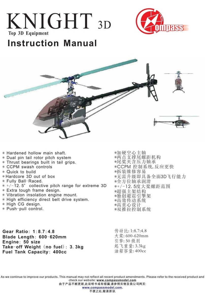
  9. Compass Knight 3D User manual

Compass Knight 3D User manual

2
M3 Nylon Nut
x 4
Skid Foot
Skid Tube
Front Plate
M3x8 Socket Head Bolt
M3 Nylon Nut
M3 Washer
Head Bolt
M3x5 Set Scre
Step 1 Landing Gear & Front Plate
x4
Locktitle is needed
Locktitle is needed Locktitle is needed
Locktitle is needed
here.
here. here.
here.
a) Use M3x20 Socket Head Bolts, Washers and Nylon Nuts to fix the Skid Foot on the
frame body.
b) Insert the 2 alumine Skid Tube into the Skid Foot, and use the M3 set Scre tight
them.
c) Use M3x8 Socket Head Bolts to fix the front plate on the body.
M3x20 Socket
M3x5 Set Scre
x 4
M3 Washer
Head Bolt x4
M3x20 Socket M3x8 Socket
Head Bolt x2
3
M3x25 Socket
Head Bolt x1
M3 Nylon
Nut x1
Main Shaft
Master Block
Belt
Gear Set
Top Bearing Holder
To sho this step clearly, some irrelvant parts have been removed in the dra ing
above.
a) Pull up the belt, circle it around the Pulley Wheel under the main Gear.
b) As sho ed above, insert the main shaft, use M3x25 bolt and Nylon Nut to fix the
Gear Set on the right position. Note: the M3 set scre is used to help inserting the
Socket Head Bolt into right directoin. It is not needed to tight it up after installing
the Gear Set.
c) Tight up the Master Block underneath the Top Bearing Holder so that the main shaft
can not move vertically. Locktitle is needed on the M3x10 Socket Head Bolt.
M3x25 Socket
Head Bolt
M3 Nylon Nut
M3x5 Set Scre
only to help hen tighting
the Socket Head Bolt.
M3x10 Sockey Head Bolt
Step 4. Main Shaft, Gear Set and Belt
M3x5 Set
Scre x1
M3x10 Socket
Head Bolt x1
4
M3x10 Socket
Head Bolts
M3 Nylon Nuts
Plate
Bolts
Bottom
M3 Washer
M3x16 Socket
Head Bolts
M3x10 Socket Head
M3x8
Hub on the En ine.
05-9001 En ine Tool
An En ine Tool is needed to ti ht the Fan
Hex Wrench
En ine
En ine Mount
Cushion
Head Bolt
Clutch
Washer
M3x12 Socket
En ine Nut
Fan & Fan
Holder
Hub
Crankcase
En ine
M3x16 Socket Head Bolts
Head Bolts x8
M3x16 Socket
x4
M3 Washer
Step 2. Install the Engine
Note: Locktitle is need on all Bolts
Head Bolts x2
in this step.
M3x8 Socket
a) Assemble the Clutch, Fan Hub,
Fan, En ine, Crankcase Holder,
E ine Mount to ather.
b) Insert the whole En ine Set from
the bottome up, Fix the En ine
Mount on the body. Then install
the Bottom Plate on the body.
M3x10 Socket
Head Bolts x4
M3 Nylon Nut
x 4
M3x12 Socket
Head Bolts x2
5
M3 Nuts
x4
Step 3 Tail, Boom, Belt and Fins
M3x15 Socket
Head x2
M3x15 Socket
Head Bolt
M3 Nylon Nut
M3x30 Socket
Head Bolt
Fin Collar
M3x40 Socket
Head Bolt
M3 Nylon
Nut
M3 Nut
a) Install t e Boom, Tail Gear Box wit Belt on t e Body.
b) t en install t e Fins, Boom Supporters on t e boom. T en fix t e tail boom
supporters on t e body, locketitle is need for t e bolts ere.
Watc out t e belt direction, make sure w en t e belt turns at t e direction as
s owed, t e tail blades turn back wards.
M3 Nylon Nut
x 8
C
M3 Was er
x4
M3x30 Socket
Head Bolts x2
M3x12 Socket
Head Bolts x2
M3x40 Socket
Head Bolts x6
M3x12 Socket
Head Bolt
M3x40 Socket
Head Bolt
M3 Nut
M3 Nylon
Nut
M3x20 Socket
Head Bolt
M3 Was er
6
M3 Nylon
Nut x1
Wash Out
Swash Plate M3x10 Set
Screw
M3x22 Socket
Head Bolt
Fly Bar
Connect
here
Connect
Here
Screw irection
Screw irection
Seasaw
A Arm
M3x10 Set
Screw x2
M3x22 Socket
Head Bolt x1
Step 5. Rotor Head, Swash Plate, Washout & Paddle
a) install the Swash Plate, Wash Out, Rotor head on the main shaft. Tight
the M3x22 Socket Head Bolt to fix the rotor head position.
b) Install the Fly Bar into the Seasaw. Use the Flybar to push the stocked
short shaft in the Seasaw out.
c) Screw the paddle on the Flybar in the showed direction. Tight the M3
Set screw to fix the Paddle position.
d) Connect the ball link on the wash out with the Swash Plate inner ring.
Connect the ball link on the A Arm with the Swash Plate outer ring.
7
Flybar Appares Here
Flybar Appares Here
Same Distance
Pallele
A few notes on Paddle and Fly Bar installation
a) make sure Flybar has been installed deep enought into the Paddle. Flybar show
appares from the hole on the paddle.
b) the centre line of Paddle and Flybar Control Arm should be pallele.
c) the Paddles should be balanced to the center of the Seasaw.
d) Locktitle is need for all set screws on Seasaw and Arms here.
M x6 Socket
Head Bolt x8
Step 6. Servos
M .5 Washer
x 0
M .5x16 Self
Tapping Bolt x 0
8
11mm
Servo Nut
M2.5x16
Head Bolt
M2.5 Washer
Bolt comes with Servo
M2x6 Socket
Self Ta ing
Bolt
Servo Horn
a) all Servo Horn should be set to 11mm from the Center.
b) use M2.5 Self Ta ing Bolt install Servos on frame.
C) use M2x6 Socket Head Bolts fix the balls on the Servo
Horn. Note the balls on Elevator Servo is in Servo Horn's
different side.
9
Boom
Main Grip
Wash Out Arms are paralledl to the Boom.
Wash Out Arm
Paralle
to the Boom
The Wash Out should be set at an angle so that the Main Grip and
Phasing Block
b) Refer to the Radio manual connect all the eletronic devices.
Step 7. Wire Up
Elevator
Pitch
Gyro
With Sponge
Receiver
Battery With
Rudder
Sponge
Throttle
Aileron
a) Install Reciver Battery Gyro and other eletronic device.
Step 8. Phasing Block
10
h
Step 9. Radio Setting Data
Pitch Curve
Throttle Curve
Pitch Setting Swash Type Setting
Hovering ID1 ID2 ID3 Autorotation JR Futaba
Loop Roll 3D Swash Type SWH
High Pitc 9~10 9~10 78.5~9 12 S3 120º SR3
Hovering 5~5.5 300N/A Aile Elev Pitch
Low Pitch -4 -6 -7 -8.5~9 -7 65% 65% 65%
Above data just give some general idea of setting. It varies by engine,blades,muffler and pilot's style.
Adjust by actual flight.
Hovering
0%
25%
50%
75%
100%
12345
Roll
0%
25%
50%
75%
100%
12345
3D
0%
25%
50%
75%
100%
12345
Autorotation
0%
25%
50%
75%
100%
12345
Loop
0%
25%
50%
75%
100%
12345
Hovering
0%
25%
50%
75%
100%
12345
Loop
0%
25%
50%
75%
100%
12345
Roll
0%
25%
50%
75%
100%
12345
3D
0%
25%
50%
75%
100%
12345
Autorotation
0%
25%
50%
75%
100%
12345
11
11mm
180& vertical
180
Guide Holes
Step10. Set Up
a) Turn on the radio and set throttle position to middle position for 0 deg.
All horn distance should be set to 11mm from centre. Use the sub trim in radio
programe to ad ust each servo to get control horn to the right angle.
b) Next is to ad ust links from servo to 2 T arms and I arm so that the T arm is horizontal
and the inner arm is horizontal. Use the Guide Holes on frame to aim the two arms
being Horizontal.
Horizontal
Inner Arm T Arm
Note: The 2 push pull link rod are not
necessarily parallel.
12
90
90
2°
can be used here as a guide.
c) Next adjust the links from T arms to Swash late
to level Swash late. A compass swash plate tool
d) Set the Wash Out Arm horinzontal.
e) Set the mixing arm 2 deg downwards
might need to be cut shorter to get
Mixing Arm
to the Flybar.
the right pitch.
Flybar
Center Line
of Mixing Arm
of Fly Bar
Center Line
f) Install main blades and set the main
blades to 0 deg pitch. One ball link
g) Install and adjust the engine link so that link is 90 deg to the servo horn and the
engine horn.
Swash late
Swash
Tool
Arm
late
06-0501
Compass
Wash Out
Horizontal
13
2 deg to Flybar.
d) Level the
Link to cut in 0 deg pitch.
f).
Linkage Length
180 deg
a)Servo Horn
and Crank rm
b)Level the T rm
Swash Plate
c) Level the
Wash Out rm
e) Set Mixing rm
f) Set main blade to
ll Linkage Length are measured in this way. In case you change ball links, you can
set the same measurement.
Linkage Length
Summary
14
168mm(6.63inch)
81.5mm(3.2inch)
41mm(1.61inch)
25mm(0.984inch)
59mm(2.31inch)
85.5mm(3.37inch)
85mm(3.35inch)
41mm(1.61inch)
Linkage Length:
Main Blade Holder to Mixing Arm: 25mm(0.984inch)x2
Fly Bar Control Arm to Wash Out Arm: 41mm 1.61 inch) x2
Mixing Arm to Swash Plate Inner Ring: 59mm 2.31inch)x2
Swash Plate Outer Ring to T Arm: 41mm 1.61inch)x2
T Arm Left to Servo Horn: 168.5mm 6.63 inch) x2
T Arm Right to Servo Horn: 81.5mm 3.2inch) x2
I Arm to Servo Horn: 85.5mm 3.37inch)x2
Engine Link: 85mm 3.35inch)x1
15
When Main Blades turn clockwisely, the Tail Blades should turn Clockwisely too.
If not, the Belt might be installed in wrong direction.
Step Canopy & Final Check
Canopy
Damper
Canopy Body
Canopy
Window
M2.5 x6 Self
Tapping Bolt
Note: Clean the Canopy with detergent or oap water before attaching the
Decal on the canopy.
16

Other manuals for Knight 3D

1

Other Compass Toy manuals

Compass 7hv User manual

Compass

Compass 7hv User manual
Compass Exo 500 User manual

Compass

Compass Exo 500 User manual

Compass Knight 600E User manual

Compass

Compass Knight 600E User manual

Compass Knight 50 User manual

Compass

Compass Knight 50 User manual

Compass Atom 6HV User manual

Compass

Compass Atom 6HV User manual

Compass 6HV Ultimate User manual

Compass

Compass 6HV Ultimate User manual

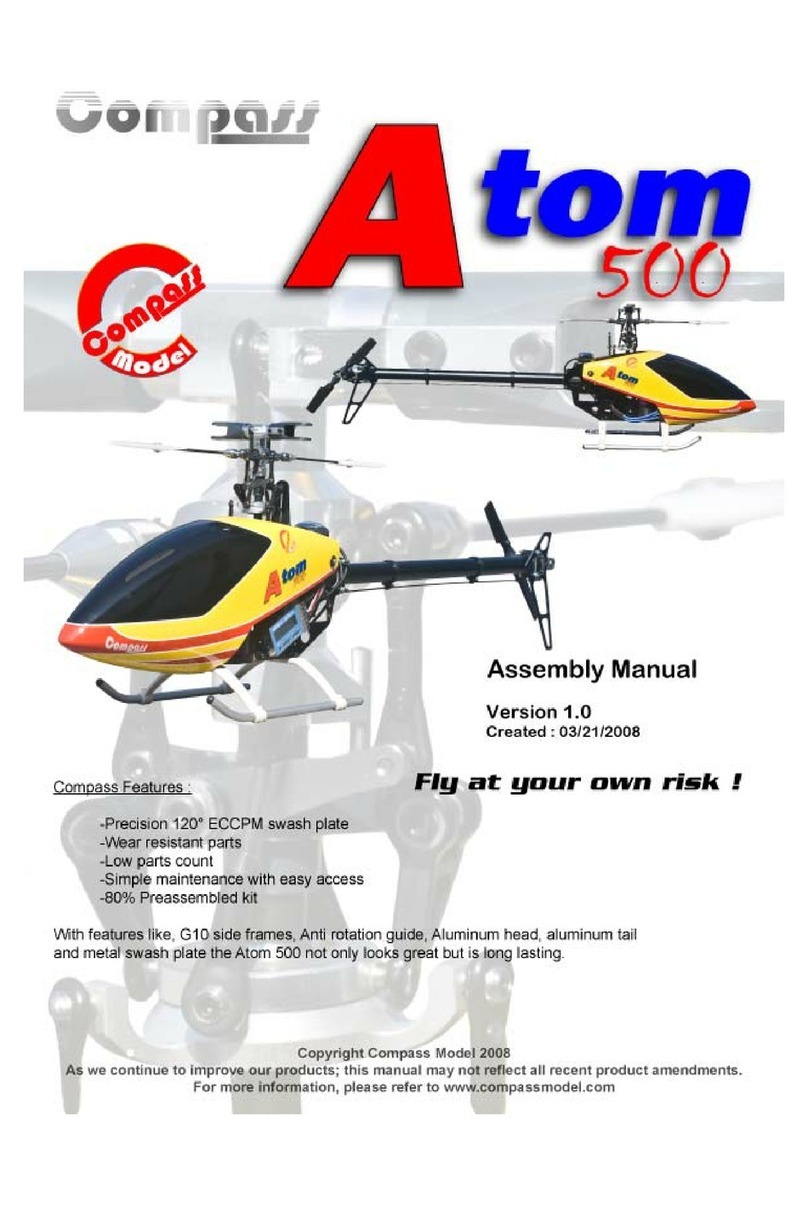
Compass Atom 500 User manual

Compass

Compass Atom 500 User manual

Compass Knight 3D User manual

Compass

Compass Knight 3D User manual

Compass Atom 6HV User manual

Compass

Compass Atom 6HV User manual

Compass 7hv Assembly instructions

Compass

Compass 7hv Assembly instructions

Compass Atom 6HV User manual

Compass

Compass Atom 6HV User manual

Compass Knight 50 User manual

Compass

Compass Knight 50 User manual

Compass WARP 360 User manual

Compass

Compass WARP 360 User manual

Compass Atom 500 User manual

Compass

Compass Atom 500 User manual

Compass 3D Plus Nitro Powered Helicopter User manual
Compass

Compass 3D Plus Nitro Powered Helicopter User manual

Popular Toy manuals by other brands

Thomas & Friends TRACKMASTER MOTORIZED RAILWAY MOTORISED... instructions

Thomas & Friends

Thomas & Friends TRACKMASTER MOTORIZED RAILWAY MOTORISED... instructions

Faller 282934 manual

Faller

Faller 282934 manual

marklin 55563 user guide

marklin

marklin 55563 user guide

Lionel Greendale owner's manual

Lionel

Lionel Greendale owner's manual

Eduard B-17G exterior manual

Eduard

Eduard B-17G exterior manual

Radica Games PINBALL 73021 instruction manual

Radica Games

Radica Games PINBALL 73021 instruction manual

Trigano J-JOU058 manual

Trigano

Trigano J-JOU058 manual

Hornby RAILROAD CLASS 43 HST Operating and maintenance instructions

Hornby

Hornby RAILROAD CLASS 43 HST Operating and maintenance instructions

AirWing 4498155 Assembly and operation guide

AirWing

AirWing 4498155 Assembly and operation guide

LEGO HOBBIT 79003 Building instructions

LEGO

LEGO HOBBIT 79003 Building instructions

LEGO Creator 31017 Assembly information

LEGO

LEGO Creator 31017 Assembly information

KDS Models Chase 360 manual

KDS Models

KDS Models Chase 360 manual

Hudora Joey Pot stilts INSTRUCTIONS ON USE

Hudora

Hudora Joey Pot stilts INSTRUCTIONS ON USE

LEGO DUPLO DISNEY JUNIOR MILES FROM TOMORROWLAND manual

LEGO

LEGO DUPLO DISNEY JUNIOR MILES FROM TOMORROWLAND manual

GREAT PLANES XPD-8 instruction manual

GREAT PLANES

GREAT PLANES XPD-8 instruction manual

FMS SBACH 342 operating manual

FMS

FMS SBACH 342 operating manual

Eduard British 155mm AS-90 SPH manual

Eduard

Eduard British 155mm AS-90 SPH manual

Faller 190066-2 manual

Faller

Faller 190066-2 manual

manuals.online logo
manuals.online logoBrands
  • About & Mission
  • Contact us
  • Privacy Policy
  • Terms and Conditions

Copyright 2025 Manuals.Online. All Rights Reserved.