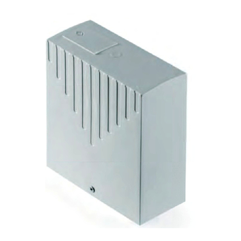
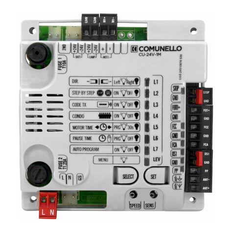
Comunello Automation QUAD-24V-HP User manual

Cod.91300171 - Rev. 07 - 23.03.21
ISTRUZIONI D’USO E DI INSTALLAZIONE
INSTALLATION AND USER’S MANUAL
INSTALLATIONS-UND GEBRAUCHSANLEITUNG
INSTRUCIONS D’UTILISATION ET D’INSTALLATION
INSTRUCCIONES DE USO Y DE INSTALACION
MANUAL DE INSTRUÇÕES DE UTILIZAÇÃO
ÛΈΌÝͿßÛèΊΉ·ΉΈÙÝ
comunello.com
AUTOMATION
QUAD - 24V - HP
Quadro elettronico di comando
Electronic control unit
Elektronische Steuerung
Panneau de commande électronique
Panel de control electrónico
Central de comando para portões automáticos
æñΐðõΓΒóóΏĀôΏóΐñýΕôΓΏêñΐóïĀ

30 COMUNELLO ®Copyright 2021 - All rights reserved
QUAD - 24V - HP
INSTALLATION AND USER’S MANUAL
Fratelli Comunello S.p.A.
Company with certied Quality Management System
UNI EN ISO 9001:2015.
EC DECLARATION OF CONFORMITY:
The undersigned Mr. Luca Comunello, representing the following manufacturer,
Fratelli COMUNELLO Spa
Via Cassola 64, 36027 Rosà (VI) – Italy
DECLARES that the equipment described below:
Description: Electronic control unit
Model: QUAD 24V HP
Is in compliance with the provisions set down in the following directives:
• 2014/30/EU (EMCD Directive) • 2011/65/EU (RoHS Directive)
• 2014/35/EU (LVD Directive)
• 1999/5/CE (R& TTE Directive)
and that all the rules and/or technical specications shown below have been applied:
EN61000-6-2:2005 + EN61000-6-3:2007
EN62233 :2008
EN301489-3
EN60335-2-103 :2003 + EN60335-1 :2012
and the following amendments.
Rosà (VI) – Italia
21-04-2019
and he also declares that it is not allowed to commission the device until the machinery where it will be incorporated or whose it will become a
component will have been identied and will have been declared in compliance with the conditions of the 2006/42 EC Directive and with the
national legislation that transpose it.
Mr. Luca Comunello
Fratelli Comunello Legal Representative
a
tiv
e

ENGLISH
31
COMUNELLO ®Copyright 2021 - All rights reserved
PRESCRIPTIONS
• The control unit does not have any type of 230 Vac power line sectioning device; it will therefore be the installer’s responsibility to install a
sectioning device in the system. An omnipolar switch with overvoltage category III must be installed. It must be positioned so as to be protected
against accidental reclosing in accordance with the provisions of point 5.2.9 of EN 12453. The wiring of the various electrical components
external to the control unit must be carried out in accordance with the prescriptions of the EN 60204-1 standard and the modications to this is
made from point 5.2.7 of EN 12453. The power supply cables can have a maximum diameter of 14 mm; the xing of the power and connection
cables must be guaranteed through the assembly of cable glands, available as optional.
• 5.2.7 of EN 12453. Power cables can have a maximum diameter of 14 mm and the Ø of power supply and connection cables must be
guaranteed by assembling the “optional” cable glands.
• For power cables it is recommended to use exible cables in insulating sheath in harmonized polychloroprene (H05RN-F) with a minimum
conductor cross-section of 1 mm2.
• When installing, use only double-insulated cables (sheathed cables) both for mains voltage connections (230V) and for SELV safety extra-low
voltage connections. Use only plastic channels, separate for low voltage wiring (230V) and for extra low voltage wiring (SELV).
• The conductors with very low safety voltage must be separated (at least 4 mm in air) from the mains voltage conductors, or they must be
adequately insulated with additional insulation having a thickness of at least 1 mm.
• Provide a device that ensures complete omnipolar disconnection of the network upstream of the automation power supply network, with
a contact opening distance at each pole of at least 3mm. These disconnection devices must be provided in the power supply network in
accordance with the installation rules and must be directly connected to the power supply terminals.
• In the case of installation inside a QUAD control panel, be careful when drilling the external casing to pass the power supply and connection
cables, and the assembly of the cable glands, to install everything so as to keep the IP rating of the box as unaltered as possible. Also pay
attention to the cables so that they are anchored in a stable manner, and not to damage the board with the puncture (g. 3B).
• The casing in the back is provided with suitable predispositions for xing to the wall (predisposition for holes by means of plugs or holes for xing
by screws). Predict and implement all the precautions for an installation that does not alter the IP rating.
• The possible assembly of a push-button panel for manual control must be done by positioning the push-button panel so that the user is not in
a dangerous position.
• The gearmotor used to move the gate must comply with the requirements of point 5.2.7 of EN 12453.
• The FOTO + output (CN2) is necessarily dedicated to powering the photocells, they cannot be used for other applications.
• The control unit can perform the photocell operation test at each cycle of operation, guaranteeing protection against the failure of Category 2
anti-crushing devices according to the provisions of point 5.1.1.6. of EN 12453. Therefore if the safety devices are not connected and / or are
not working the control unit is not enabled for operation.
The device cannot be used by children under the age of 8 or by persons with reduced physical, sensory or mental abilities, or lacking in
experience or the necessary knowledge, if not under supervision or after they have received instructions relating to safe use of the appliance
and understanding of the dangers inherent in it.
USER CAUTION
Do not allow children to play with the device and keep remote controls away from them. Cleaning and maintenance intended to be carried out
by the user must not be carried out by children without supervision.
Do not allow children to use the device as a toy and keep remote controls out of reach.
NOTE: keep this instruction manual and respect the important safety instructions contained in it. Failure to comply with the regulations could
cause damage and serious accidents.
Examine the system frequently to detect any signs of damage.
32 COMUNELLO ®Copyright 2021 - All rights reserved
1 DESCRIPTION OF CONNECTIONS
CN2
2nCH
2nCH
FOT+
FOT-
DS2
GND
DS1
S8K2
GND
PPED
PP
ELS+
ELS-
24V
GND
+LED
ANT-
ANT+
CN4
CN8 CN5
CN1 CN3
L24
L24
M1+
M1
M2+
M2
FC2
FA2
GND
E2
E2+
GND
E1
E1+
FC1
FA1
Motors outputs
2x 75W
BROWN
GREEN
BLUE
WHITE
BLUE
Schielding
Pole
Antenna Cable
230Vca
Aliment.
Primary
Transf.
FUSE 2:
T1,6A 250V
24Vcc Electric lock output
+ 24Vcc (max 5W)
GND
+ 24Vcc (max 4W) Indicator light
N.C. Photocells
DS2 input
N.C. Photocells
DS1 input
STOP input/8K2
input for resistive
hedges
N.O. Pedestrian input
N.O. Step-by-step input
N.A. output aux radio channel. (30V 1A)
24Vcc Power supply (5W)
Limit Switch M2
FCA-Open
FCC- Closed
Limit Switch M1
FCA-Open
FCC- Closed
Encoder
Motor 2
Encoder
Motor 1
Flashing light output
24VDC (max 25W)
Second.
Transf.
Back-up
battery
FUSE 1:
T15A 250V
ddEd/KE ^ϭ^ϮŝŶƉƵƚĂŶĚ^dKWϴŬϮŝŶƉƵƚďŽƚŚEĂƌĞĐůŽƐĞĚďLJĨĂĐƚŽƌLJƚŚƌŽƵŐŚũƵŵƉĞƌ
dŽǁŝƌĞƚŚĞƉŚŽƚŽĐĞůůƐŽƌƚŚĞƐƚŽƉƉƵƐŚďƵƩŽŶƌĞŵŽǀĞƚŚĞũƵŵƉĞƌƐĨƌŽŵƚŚĞƌĞůĞǀĂŶƚŝŶƉƵƚƐ
BROWN
GREEN
WHITE

ENGLISH
33
COMUNELLO ®Copyright 2021 - All rights reserved
DIP SWITCH SW1
The SW1 Dip-Switches allow you to select the 1 or 2 motor function
and dene which of the two motors starts rst and which second. TRIMMER SENS: It regulates the SENSITIVTY of motors
1
1
ON
2
MOTEUR
NON PRIS
EN COMPTE
2
MOTEURS
RETARD
MOT. 2 2
MOTEURS
RETARD
MOT. 1
1
ON
2 1
ON
2
SW1 SW1 SW1
Turning with a screwdriver towards the + increases the speed of the
motor stroke during the slowing down phase
DIP SWITCH SW2
The SW2 Dip-Switches allow to change the direction of stroke
of each motor without physically intervening on the electrical
connections in the terminal block. TRIMMER SPEED: It regulates the SPEED of motors
INV
1
ON
2
OFF INV
OFF INV
MOT 1 INV
OFF INV
OFF INV
MOT 2 INV
MOT 1 INV
MOT 2
1
ON
2 1
ON
2 1
ON
2
SW2 SW2 SW2 SW2
Turning with a screwdriver towards the + increases the motor speed
during the stroke.
TRIMMER SLOWING: It regulates the slowdown speed of motors
Turning with a screwdriver towards the + increases the sensitivity and
therefore the motor will block its stroke more quickly if an obstacle is
detected.
2 WIRES CONNECTION TABLE:
TAB.01
n° DESCRIPTION CABLE LENGTH from 1m to 20m LENGHT from 20m to 50m
1 Power supply
EN standard 50575, in
the list of harmonized
rules for the Regulation
CPR 305/2011, Com.
2016/C 209/03
2 x 1.5 mm
2
2 x 2.5 mm
2
6A Motor power supply 2 x 2.5 mm
2
2 x 4.0 mm
2
2 Flashing light 2 x 0.5 mm
2
2 x 1.0 mm
2
4A, 5A TX photocell 2 x 0.5 mm
2
2 x 1.0 mm
2
4B, 5B RX photocell 4 x 0.5 mm
2
4 x 1.0 mm
2
6 Key selector 3 x 0.5 mm
2
3 x 1.0 mm
2
6B Limit switches 3 x 0.5 mm
2
3 x 1.0 mm
2
6C Encoder 3 x 0.5 mm
2
3 x 1.0 mm
2
3 Antenna RG58 Max. 20m
The table refers to the example of wiring shown in the ABACUS model manual for swing motors.
If the cables are of a different length than those shown in the table, the section of the cables must be determined based on the actual absorption of the connected
devices.

34 COMUNELLO ®Copyright 2021 - All rights reserved
The requirements are reported in the EN 50575: 2014 standard:
With the publication of the standard EN 50575, in the list of harmonized standards for Regulation CPR 305/2011, Com. 2016 / C 209/03,
also electric cables, already subject to CE marking for the Low Voltage Directive 2014/35 / EU, must be CE marked also under the CPR
Regulation.
In the eventualities of connections with devices connected in parallel on the same power supply line, the sizing of the cables shown in Table
1must be re-evaluated on the basis of the absorptions and the actual distances.
3 TECHNICAL SPECIFICATIONS
Back-up Battery input: 24 V 7A/h max.
Flashing light output: 24 V 25 W max.
Motors outputs: 24 V 2 x 75 W max.
Electric lock output: 24 V 12W max.
Photocells power supply: 24 V 5 W max.
Indicator light output: 24 V 4 W max.
Working temperature: - 20 ÷ 55 °C
Radio receiver: 433 Mhz
Transmitters: 18 Bit o Rolling Code
Max TX codes stored in memory: 120(CODE o CODE PED/2°CH)
Board dimensions: 160 x 107 mm.
Fuse 1 : T 15 A 250V (Delayed fuse)
Fuse 2: T 1.6 A 250V (Delayed fuse)
4 CONNECTION WITH ONE MOTOR
4.1 FORT
MOTOR 1 OUTPUT
RED
+24V
BLACK
GND
MOTOR 2 OUTPUT
NOT USED
CN4
L24
L24
M1+
M1
M2+
M2
1
MOTOR
1
ON
2
SW1
M2 NOT
CONSID.
In this mode SW1 has been adjusted with:
DIP1 OFF : only MOTOR 1 is considered
DIP2 ON: not used
SW2 setting to have an opening to the LEFT (inner side view) SW2 setting to have an opening to the Rights (inner side view)
INV
MOT1
1
ON
2
SW2
INV
MOT1
1
ON
2
SW2

ENGLISH
35
COMUNELLO ®Copyright 2021 - All rights reserved
4.2 SALIENT
Single motor installation (up to 9 m
2
)
MOTOR 1 OUTPUT
RED
+24V
BLACK
GND
MOTOR 2 OUTPUT
NOT USED
CN4
L24
L24
M1+
M1
M2+
M2
IMPORTANT NOTE: DO NOT CHANGE THE CONFIGURATION.
Opens to LEFT, closes to Rights (left prole view, as in the image).
Double motor installation (up to 16 m2)
F1
FC FAFC FA GND E1 +GND E1 +
BATT +
BATT -
LAMP +
LAMP -
MOT1 +
MOT1 -
MOT2 +
MOT2 -
)V42TNEILAS()DRAOBNIAMHTIW-V42TNEILAS(
MINTERNAL MOTOR 24V (N.C.) END STOP OPEN MOTOR
(N.C.) END STOP CLOSE MOTOR
LAMP
LAMP+
COMMON
END STOP CLOSED
END STOP OPEN
0 V
+ 24 V
CN1
CN3
12345678
10 9 8 7654321
MOT2 MOT1ENC2 ENC1
BLACK
BLACK
BLUE

36 COMUNELLO ®Copyright 2021 - All rights reserved
5 CONNECTION WITH TWO MOTORS
5.1 ABACUS - connection diagram of the motors
DELAY OF THE MOTOR no.2
1 2
2
MOTORS
DELAY
MOT.2
1
ON
2
SW1
DIP1 ON = 2 motors conguration
DIP2 OFF = Delay of motor no. 2
INV
OFF
INV
OFF
1
ON
2
SW1
DIP1 OFF = inversion MOTOR no.
1 disabled
DIP2 OFF = inversion MOTOR no.
2 disabled
DELAY OF THE MOTOR no.1
1 2
2
MOTORS
DELAY
MOT.1
1
ON
2
SW1
DIP1 ON = 2 motors conguration
DIP2 ON = Delay of motor no. 1
INV
OFF
INV
OFF
1
ON
2
SW2
DIP1 OFF = inversion MOTOR no.
1 disabled
DIP2 OFF = inversion MOTOR no.
2 disabled
Wire connection of the motors (version without encoder) to the control unit:
+24V con M1 +
0V con M1 -
+24V con M2 +
0V con M2 -
CN4
L24
L24
M1+
M1
M2+
M2

ENGLISH
37
COMUNELLO ®Copyright 2021 - All rights reserved
5.2 RAM - connection diagram of the motors
DELAY OF THE MOTOR no.2
1 2
2
MOTORS
DELAY
MOT 2
1
ON
2
SW1
DIP1 ON = 2 motors conguration
DIP2 OFF = Delay of motor no. 2
INV
OFF
INV
OFF
1
ON
2
SW2
DIP1 OFF = inversion MOTOR no.
1 disabled
DIP2 OFF = inversion MOTOR no.
2 disabled
DELAY OF THE MOTOR no.1
1 2
2
MOTORS
DELAY
MOT.1
1
ON
2
SW1
DIP1 ON = 2 motors conguration
DIP2 ON = Delay of motor no. 1
INV
OFF
INV
OFF
1
ON
2
SW2
DIP1 OFF = inversion MOTOR no.
1 disabled
DIP2 OFF = inversion MOTOR no.
2 disabled
Wire connection of the motors to the control unit:
+24V con M1 +
0V con M1 - +24V con M2 +
0V con M2 -
M
+24V
0V
M
+24V
0V
CN4
L24
L24
M1+
M1
M2+
M2

38 COMUNELLO ®Copyright 2021 - All rights reserved
5.3 CONDOR - connection diagram of the motors
DELAY OF THE MOTOR no.2
1 2
2
MOTORS
DELAY
MOT 2
1
ON
2
SW1
DIP1 ON = 2 motors conguration
DIP2 OFF = Delay of motor no. 2
INV
OFF
INV
MOT 2
1
ON
2
SW2
DIP1 OFF = inversion MOTOR no.
1 disabled
DIP2 ON = inversion MOTOR no. 2
enabled
DELAY OF THE MOTOR no.1
1 2
2
MOTORS
DELAY
MOT 1
1
ON
2
SW1
DIP1 ON = 2 motors conguration
DIP2 ON = Delay of motor no. 1
INV
OFF
INV
MOT 2
1
ON
2
SW2
DIP1 OFF = inversion MOTOR no.
1 disabled
DIP2 OFF = inversion MOTOR no.
2 disabled
Wire connection of the motors (version without encoder) to the control unit:
Conguration - MASTER ON THE LEFT, SLAVE ON THE Rights
MOTOR 1 with control unit
+24V/Red M1+
0 V/Black M1 -
MOTOR 2 without control unit
+24 V M1+
0 V M1 -
2nCH
2nCH
FOT+
FOT-
DS2
GND
DS1
S8K2
GND
PPED
PP
ELS+
ELS-
24V
GND
+LED
ANT-
ANT+
L24
L24
M1+
M1
M2+
M2
FC2
FA2
GND
E2
E2+
GND
E1
E1+
FC1
FA1
M
+24V
0V
Red Black

ENGLISH
39
COMUNELLO ®Copyright 2021 - All rights reserved
5.4 EAGLE- connection diagram of the motors
DELAY OF THE MOTOR no.2
1 2
2
MOTORS
DELAY
MOT 2
1
ON
2
SW1
DIP1 ON =
2 motors conguration
DIP2 ON = Delay motor 1
INV
OFF
INV
MOT 2
1
ON
2
SW2
DIP 1 ON =
MOTOR 1 inversion
activated
DIP2 OFF =
MOTOR 2 inversion
deactivated
DELAY OF THE MOTOR no.1
1 2
2
MOTOR
DELAY
MOT. 1
1
ON
2
SW1
DIP1 ON = 2 motors
conguration
DIP2 OFF = Delay motor 2
INV
OFF
INV
MOT. 2
1
ON
2
SW2
DIP 1 ON = MOTOR 1 inversion
activated
DIP2 OFF = MOTOR 2 inversion
deactivated
Wire connection of the motors (version without encoder) to the control unit:
Conguration - MOTOR NO.1ON THE LEFT, MOTOR NO.2 ON THE Rights
MOTOR 1
+24V/Red M1+
0V/Blue M1 -
MOTOR 2
+24V/Red M2+
0V/Blue M2 -
CN4
L24
L24
M1+
M1
M2+
M2
Red
Red
Black
Black

40 COMUNELLO ®Copyright 2021 - All rights reserved
5.5 CONDOR 500 / CONDOR 500 S - connection diagram of the motors
DELAY OF THE MOTOR no.2
1 2 1 2
CONDOR 500 CONDOR 500 S
2
MOTORS
DELAY
MOT. 2
1
ON
2
SW1
DIP1 ON = 2 motors conguration
DIP2 OFF = Delay of motor no. 2
INV
OFF
INV
MOT. 2
1
ON
2
SW2
DIP1 OFF = inversion MOTOR no.
1 disabled
DIP2 ON = inversion MOTOR no. 2
enabled
DELAY OF THE MOTOR no.1
1 2 1 2
CONDOR 500 CONDOR 500 S
2
MOTORS
DELAY
MOT. 1
1
ON
2
SW1
DIP1 ON = 2 motors conguration
DIP2 ON = Delay of motor no. 1
INV
OFF
INV
MOT. 2
1
ON
2
SW2
DIP1 OFF = inversion MOTOR no.
1 disabled
DIP2 ON = inversion MOTOR no. 2
enabled
Wire connection of the motors (version without encoder) to the control unit:
Conguration - MOTOR NO.1 ON THE LEFT, MOTOR NO.2 ON THE RIGHT
CN4
L24
L24
M1+
M1
M2+
M2

ENGLISH
41
COMUNELLO ®Copyright 2021 - All rights reserved
6 MENU DESCRIPTION AND PROGRAMMABLE FUNCTIONS
The control panel has a MAIN MENU and three sub-menus called EXTENDED MENUS to customize the programming and the various system
functions.
Pressing the SELECT button several times in succession you can scroll through the menu displayed by the 7 LEDs to choose the desired
function (ashing LED correspondingly ashing) and change its functionality with the SET button (the LED becomes xed with function enabled
or, conversely, off with function disabled).
THE “LEV” LED STATUS INDICATES WHICH MENU IS ACTIVE”
Use the SELECT key by pressing it several times to select the desired function (the corresponding LED ashes) in the displayed menu and
conrm with the SET key:
The rst available menu is the MAIN menu summarized in Tab no. 2:
MAIN MENU • Press the SELECT button and select the desired function from the
main menu The LEV function LED stays on FIXED:
LIVEL 0 - MAIN MENU
LED FUNCTION DESCRIPTION LED ON LED OFF DEFAULT
L1 STEP BY STEP Selection of the opening logic Open-Stop-Close-Stop (it closes after the pause time in a partial opening
phase)
Automatic (Open-Close)
L2 CODE TX Storage of remote controls Memorised controls Empty storage
L3 CONDO Activate the "Condominium"
function
After the rst one, the other inputs are ignored during the opening and the
pause time
Disabled function
L4 MOTOR TIME Storage of the motor stroke with
slowdowns
Stored stroke 30 seconds, without slowdown
(default)
L5 PAUSE TIME Automatic closing setting Automatic closing period stored Not active
L6 DELAY Adjustment of the delay between
the 2 leaves
4 sec. in OPEN, adjustable from 4 to max. 15 sec. in CLOSE Leaf delay disabled
L7 AUTO PROGRAM Self-learning of the stroke with
slowdowns
Memorized self-learning of the stroke Disabled function
Table 2
The second menu is the one dened as EXTENDED 1 and to access the programmable functions follow the instructions given in Tab. 3:
EXTENDED
MENU 1
• Press the SELECT button and scroll the LED menu until you reach
the LEV LED;
• Press SET once to access the EXTENDED menu 1.
The LED of the LEV function FLASHES with this frequency
LIVEL 1 - EXTENDED MENU 1
LED FUNCTION DESCRIPTION LED ON LED OFF DEFAULT
L1 HOLD-TO-RUN Hold-to-run input Enabled function Disabled function
L2 PEDESTRIAN /
SINGLE LEAF
PUSHBUTTON
Conguration of pushbuttons inputs
PP and PPED
N.O. PPED button acts like single leaf (performing the stored stroke of
MOT1)
OPEN and CLOSE by 2 different buttons:
PP: Open
PPED: Close
Partial opening/pedestrain leaf
PP: Open / Close button
PPED: partial open of MOT1
L3 PEDESTRAIN
BUTTON / DS3
Conguration of the PPED input
as partial opening or as additional
photocell input
Conguration of N.O. PPED input as DS3
Conguration of the PPED input as
N.O. Pedestrian input
L4 PHOTOTEST Perform the photocell test before
each movement
Enabled function Disabled function
L5 DS2 STOP IN
CLOSE
Conguration of DS2 photocells
input
STOP in CLOSE once the contact is open, then reversal Reversal in CLOSE
L6 DS1 PARTIAL
INVERTION
Conguration of DS1 photocells
input
Partial reversal in CLOSE Complete reversal in CLOSE
L7 BLOCK / 8K2
Conguration of N.C. STOP or 8.2
K Ohm resistive input.
8.2 K Ohm resistive input conguration N.C. STOP pushbutton
Table 3

42 COMUNELLO ®Copyright 2021 - All rights reserved
The third menu is the one dened as EXTENDED 2 and to access the programmable functions follow the instructions given in Tab. 4:
EXTENDED
MENU 2
• Press the SELECT button and scroll the LED menu until you reach
the LEV LED;
• Press SET twice to access the EXTENDED menu 2.
The LED of the LEV function FLASHES with this frequency
LIVEL 2 - EXTENDED MENU 2
LED FUNCTION DESCRIPTION LED ON LED OFF DEFAULT
L1 BRAKE Enabling of the electronic brake Enabled function Disabled function
L2 STEP BY STEP 1 Step-By-Step logic Open-Stop-Close-Stop (It DOESN'T close after the pause time in a partial
opening phase)
Disabled function
L3 ALWAYS CLOSE Enables the sending of a CLOSE
command when the power is turned
on again
Enabled function Disabled function
L4 FOLLOW ME The motor automatically closes in
5 sec after passing through DS1
photocell
Enabled function Disabled function
L5 PEDESTRIAN TIME Storage of motor no.1 partial stroke
with slowdowns
Partial stroke of motor no.1 stored 10 sec., without slowdowns
L6 2°CH MONOSTABLE
/ BISTABLE/TIMED
MONO.
Setting the aux. relay of the 2°CH
as Bistable / Monostable /
Temporised monostable
Bistable command Monostable command (impulsive)
L7 REMOTELY
PROGRAMMING
Enable the remote control memory
function without acting on the
control unit
Enabled function Disabled function
Table 4
The fourth and last menu is dened as EXTENDED 3 and to access the programmable functions follow the instructions given in Table 5:
EXTENDED
MENU 3
• Press the SELECT button and scroll the LED menu until you reach
the LEV LED;
• Press SET 3 times to access the EXTENDED menu 3.
The LED of the LEV function FLASHES with this frequency:
LIVEL 3 - EXTENDED MENU 3
LED FUNCTION DESCRIPTION LED ON LED OFF DEFAULT
L1 SOFT STOP Setting of gradual slowdown at the
end of the movement
Enabled function Disabled function
L2 SOFT START Setting of gradual slowdown at the
beginning of the movement
Enabled function Disabled function
L3 RELEASE STROKE
MAX FORCE/
RELEASE STROKE
Before opening, the closing thrust is
activated for the electric lock release
Active function Disabled function
L4 SLAM LOCK MAX
FORCE / SLAM
LOCK
Activation of the push in closing for
electric lock release
Active function Disabled function
L5 ELS / CMD PED Activation of the electric lock as
PPED input
Enabled function Disabled function
L6 LAMP/INDICATOR
LIGHT/COURTESY
LIGHT/
Flashing light set as pilot light or
courtesy light
The courtesy light / warning light becomes an intermittent output, while the
lamp output becomes a courtesy light”
Flashing light
L7 PRELAMP / LAMP IN
PAUSE
Activation of the pre-ashing of 3
sec. before closing / Flashing during
the pause time
Active function: preash in closing / Flash during pause time Disabled function
Table 5
Note: The control unit allows to be programmed if all the safety devices (N.C. inputs on terminals) grant a contact closed.

ENGLISH
43
COMUNELLO ®Copyright 2021 - All rights reserved
7 DETAILED DESCRIPTION OF ALL FUNCTIONS
7.1 ELECTRICAL CONNECTIONS
CN1:
BATT+24V: Back-up Battery + input
BATT-24V: Back-up Battery – input
LAMP+24V: 25W Flashing Light + output
LAMP-24V: 25W Flashing Light – output
MOT1+: Motor 1 + Output.
MOT1-: Motor 1 – Output
MOT2+: Motor 2 + Output
MOT2-: Motor 2 – Output
ELS+: Electric lock +24Vdc
ELS-: Electric lock -
CN2:
2nd CH: Aux Radio CH Output (Free Contact max load 30V 1A)
FOTO +: Photocell control and power supply
FOTO -: Common GND input
DS2: Safety device 2 input (N.C.)
GND: Common GND input
DS1: Safety device 1 input (N.C.)
STOP 8K2: STOP Input / 8K2
GND: Common GND input
P PED: Pedestrian Pushbutton/Single Leaf/open input (N.O.)
PP: Open-close/close command Pushbutton input (N.O.).
ELS+: Electric lock +24Vdc
ELS-: Electric lock -
24V 5W: Services output (+ 24Vdc)
GND: Common GND input
+24V LED: Indicator light output (+24 V 4 W)
ANT-: Antenna Ground Input.
ANT+: Antenna Hot pole Input.
CN3:
ENC1 +: Motor 1 Encoder Power Input
ENC1 E: Motor 1 Encoder Signal Input
GND: Common GND input
MOT1 FCA: Motor 1 Opening Limit Switch Input (N.C.)
MOT1 FCC: Motor 1 Closing Limit Switch Input (N.C.)
ENC2 +: Motor 2 Encoder Power Input”
ENC2 E: Motor 2 Encoder Signal Input
ENC2 GND: Motor GND input
MOT2 FCA: Motor 2 Opening Limit Switch Input (N.C.)
MOT2 FCC: Motor 2 Closing Limit Switch Input (N.C.)
CN4: Secondary transformer
CN5: Primary transformer
CN8:
L: 230 V line input (phase)
N: 230 V line input (neutral)
7.2 FUNCTIONAL CHARACTERISTICS
7.2.1 AUTOMATIC OPERATION (OPEN/CLOSE):
When either a stored remote or the connected low voltage pushbutton panel is used to control the gate, operation is as follows: the rst
command opens the gate until motor time elapses or until the gate reaches its opening limit position; the second command closes the
gate; if another command is transmitted before motor time has elapsed or before one of the two limiters has been reached, the control unit
reverses the movement direction during both opening and closing.
7.2.2 STEP-BY-STEP OPERATION:
When the LED L1 of the main menu is turned on, when either the remote or the low voltage control pushbuttons are used to control the
gate, operation is as follows: the rst command opens the gate until motor time or until the gate reaches its opening limit position; the
second command closes the gate; if another command is transmitted before motor time has elapsed or before one of the limit stops has
been reached, the control unit stops the movement. Another command causes the gate to start moving again in the opposite direction.
7.2.3 STEP-BY-STEP 1 OPERATION:
Using either the remote control ( LED No. 1 on ) or the low voltage buttons to operate the gate, the following operation will be effected: the
rst command opens the gate until the motor limit time expires or until the gate reaches its opening limit. The second command closes the
gate; if a command is sent before the end of the motor limit time or when one of the two limit switches is reached, the control unit always

44 COMUNELLO ®Copyright 2021 - All rights reserved
stops motion. When opening after the pause time, it does not automatically close the door (even if the pause time has previously been
programmed). A further command determines the resumption of motion in the opposite direction.
7.2.4 AUTOMATIC CLOSING:
The control unit can be set up to close the gate automatically without sending any additional commands.
The selection of this type of operation is described in Pause time programming mode PAUSE TIME.
7.2.5 PEDESTRIAN OPENING:
The control unit allows, using both the remote control and the Ped input button, the operation of the Motor no. 1 only, for a programmable time.
7.2.6 SINGLE LEAF:
Despite being utilized in the conguration for a 2-operator gate opener, the control unit allows the Pedestrian/Single Leaf pushbutton to start
exclusively Operator no.1, in accordance with the programmed stroke.
7.2.7 EMERGENCY STOP INPUT:
The control unit allows the connection of an emergency stop pushbutton (NC). Pressing this pushbutton
irrespective of the current operating mode of the control unit will cause immediate stopping of the gate movement.
An additional gate movement command will be valid provided the emergency stop input is deactivated and, in any case the control unit will
reverse the motion of the automatism with 5 seconds pre-ashing.
Important Note: Jumper this input if it is not to be used.
7.2.8 PHOTOCELLS:
Photocells can be powered by and connected to the control unit in accordance with directive EN 12453.
DS1 Input (NC): Tripping of the photocells during opening is disregarded, while during closing it causes reversal of the direction of
movement.
DS2 Input (NC): Tripping during opening causes momentary stopping of the gate; once the safety is freed the control unit resumes the
opening movement. Tripping during closing causes reversal of the direction of movement.
Programmable input DS3 (NC): Tripping during opening causes reversal of the direction of movement. Tripping during closing is
disregarded.
To allow operation in compliance with EN 13849-1 Category 2 a photocell test is performed before each movement. In order to perform this
test it is essential to power the transmitter of each pair of photocells on the specic “Photocells Power and Control” output (outputs 3 and
5 of terminal strip CN2), while the receiver of each pair must be powered via the “Users Output” (outputs 14 and 15 of terminal strip CN2).
The control unit enables the movement only if the test is passed; if it is not, the control unit inhibits all movements and an alarm condition
is signalled by blinking of all the programming LEDs on transmission of each command.
7.2.9 OPENING AND CLOSING LIMIT SWITCHES:
The control unit allows for the connection of N.C. Opening and Closing limit switches. Tripping in the associated operating stages causes
immediate stopping of movement with correspondence between limit switches and motor 1 or 2.
Important note: Do not jumper these inputs if they are not used.
7.2.10 ENCODER MOTOR 1 AND MOTOR 2:
The control unit allows the connection of an Encoder for each motor. The use of Encoders improves Obstacle Detection and ensures
greater precision during the execution of manoeuvres.
7.2.11 INDICATOR LIGHT:
The control unit allows a 24V DC indicator light to be connected to display the status of the gate opener.
- Light off: gate closed
- Light on: gate open
- Slow blinking: opening movement;
- Rapid blinking: closing movement.
7.2.12 OPERATION WITH TIMER:
The control unit allows a timer to be connected in place of the open – close push-button.
E.g.: at 08.00 am the timer closes the contact and the control unit commands an opening movement; at 06.00 pm the timer opens the
contact and the control unit commands a closing movement.
From 08.00 am – 06.00 pm at the end of the opening cycle, the control unit disables the ashing light, automatic closing and the remotes.
7.2.13 ELECTRIC LOCK CONTROL OUTPUT:
The control unit features an output to control a 24V DC 15W max. electric lock. The command is switched on at each initial opening
movement for a period of 2 seconds.
7.2.14 BUFFER BATTERY:
The control unit is equipped with a built-in 24 V maintenance battery charger.
The control unit allows the connection of a buffer battery of 7Ah recommended capacity, which will allow a number of emergency manoeuvres
at reduced speed. The ashing light, if present, in the absence of mains voltage, will work only for the rst 4 seconds of the manoeuvre.

ENGLISH
45
COMUNELLO ®Copyright 2021 - All rights reserved
7.3 DIP-SWITCHES AND TRIMMERS ADJUSMENTS
Important Note: change the settings of dip-switches SW1 and SW2 with the control unit off and only subsequently repeat the control unit
programming procedure.
7.3.1 MOTOR 1 OR MOTOR 2 DELAY CONTROL AND ENABLING OF 1 OR 2 MOTORS
1
1
ON
2
MOTOR
NOT
CONSID.
2
MOTORS
MOTOR
2 DELAY
2
MOTORS
MOTOR
1 DELAY
1
ON
2 1
ON
2
SW1 SW1 SW1
Important note: in the case of 1 motor operation (Dip Switch 1 of SW1 set in OFF position), Dip Switch 2 of SW1 must be set in OFF
position, otherwise SW2 is disabled.
The electronic control unit is equipped with a dip-switch SW1 that is used to select operation with 1 or 2 motors and to dene which of the
two starts rst and which starts second.
7.3.2 MOTOR 1 AND MOTOR 2 STROKE DIRECTION
INV
OFF INV
OFF INV
MOT 1 INV
OFF INV
OFF INV
MOT 2 INV
MOT 1 INV
MOT 2
1
ON
21
ON
2 1
ON
2 1
ON
2
SW2 SW2 SW2 SW2
The electronic control unit is equipped with dip-switches that can be used to change the stroke direction of each connected motor without rewiring
the electrical connections: dip-switch 1 controls Motor 1 while dip-switch 2 controls Motor 2.
7.3.3. DECELERATION (SLOWING):
The motors deceleration function is used on gates to prevent the moving leaves from slamming at speed into the limit stops at the end of the
opening and closing strokes.
During Motor Time programming the control unit allows programming of deceleration in the required points (immediately before full opening and
full closing); in addition, using the “SLOWING” trimmer the force intensity can be adjusted during the deceleration phase in three ne adjustment
level settings.
7.3.4. MOTOR SPEED ADJUSTMENT (SPEED):
The electronic control unit is equipped with a “SPEED” trimmer for adjustment of the speed delivered by the Motors, completely managed by
the microprocessor.
Adjustment can be performed in a range between 50% and 100% of maximum speed.
Initial starting torque can be set for each movement by feeding the operator at full power for 2 seconds, even if operator speed control is
enabled.
Important notes:
- Initial starting torque is disabled automatically if the Soft Start function is enabled;
- If the “FORCE” trimmer is adjusted, the self-learning procedure must be repeated because the movement and deceleration times may
change.
7.3.5. OBSTACLE DETECTION (SENS):
The electronic control unit is equipped with a “SENS” trimmer, completely managed by the microprocessor, for adjustment of the opposing
Force required to detect the presence of an obstacle. The adjustment can be made with a trip time from a minimum of 0.1 seconds to a
maximum of 10 seconds
ATTENTION: with the sensitivity set at the minimum level, it is recommended to install a safety edge.
Important notes:
- the detection of the obstacle causes the brief reversal of the motion during closing and opening.
- In the absence of limit switches connected to the control unit the detection of the obstacle always causes the brief inversion of the

46 COMUNELLO ®Copyright 2021 - All rights reserved
motion except in the last 5 sec. of the stroke in which it makes a stop.
- In the absence of encoders and electronic limit switches, the detection of the obstacle takes place by current measurement. To
guarantee this functionality it is necessary to adjust the slow-down trimmers as follows:
Minimum recommended settings for obstacle / limit switch
MODEL
FORT 400
FORT 600/ 1000
CONDOR 220
CONDOR 350
EAGLE 350
RAM220
RAM 300/500
ABACUS 220
ABACUS 300/500
SALIENT
SLOWING
80% 30% 80% 30% 30% 80% 30% 80% 30% 30%
SPEED
50% 20% 50% 20% 20% 50% 20% 50% 20% 20%
In the absence of encoder and limit switch, in the last 5 seconds of the motor time, the stop of the leaves is interpreted as the limit
switch.
7.3.6 BLACK-OUT
In case of power failure and subsequent reactivation of the mains voltage, the rst maneuver will be opened with a xed and reduced speed
compared to the trimmer SPEED ; when the presence of a mechanical blockage is encountered, in the absence of an electric limit switch,
the leaves do not go into obstacles, but execute a STOP. While sending a later input, the leaves always close at a reduced speed until they
are completely closed. The following movement will be done with the speeds dened by the trimmers.
8 DETAILED DESCRIPTION OF THE PROGRAMMING
PROGRAMMING:
SELECT key: it determines the type of function to be memorized, as indicated by the blinking of the LED.
By pressing the key several times, it is possible to scroll the menu and move to the desired function. The selection remains active for 10
seconds, displayed by the ashing LED; when this interval elapses, the control unit exits programming.
SET key: it conrms and changes the programming according to the type of function determined by the SELECT key.
Following conrmation, the respective LED remains on / off for about 2 sec. and then starts ashing again.
Important notes:
- the function of the SET key can also be replaced by the remote control if previously programmed (LED L2 CODE TX lit).
- Programming enabled only with the closure of N.C contacts enabled.
8.1 MAIN MENU
L1 STEP BY STEP Step-by-step Automatic (Open-Close)
L2 CODE TX Remote control stored No remote control stored
L3 CONDO ON OFF
L4 MOTOR TIME Complete stroke stored 30 s. (no slowdowns)
L5 PAUSE TIME With automatic closure OFF
L6 DELAY ON OFF
L7 PRG AUTOM ON OFF
LEV MENÙ ON
8.1.1 LED L1 - STEP BY STEP or OPEN-CLOSE:
Programming
In the default conguration the control unit is set with “Step-By-Step” operating logic enabled (LED no.1 ON);
if the “Automatic Open-Close” operating logic is required (LED no.2 OFF), proceed as follows:
• By the key SELECT, position yourself on the blinking LED no.1;
• Press the SET key;
• The LED L1 turns off and programming will be completed.
Repeat the procedure if you wish to restore the previous conguration.
8.1.2. LED L2 - CODE TX:
CODE TX: Remote controls storage
Up to 120 remotes with different codes of either the xed or the rolling code type can be saved on the control unit
Remote control code programming of the total opening (Mot. no. 1 + Mot. no.2):

ENGLISH
47
COMUNELLO ®Copyright 2021 - All rights reserved
• By the key SELECT, position yourself on the blinking LED 2 “CODE TX”;
• Press key SET once to memorize the PP channel;
• Send the selected code with the remote control;
• The LED L2 will remain steady on for a second to indicate that programming has been completed;
• The LED L2 starts to blink again to indicate that you have 10 additional sec. to store a new code;
• On expiry of those 10 sec.the LED L2 will remain steady on.
Remote control code programming of the partial / pedestrian opening (Mot. no. 1):
• By the key SELECT, position yourself on the blinking LED L2 “CODE TX”;
• Press key SET twice to memorize the PPED channel and the led will modify its blinking (110110110);
• Send the selected code with the remote control;
• The LED L2 will remain steady on for a second to indicate that programming has been completed. The extra time of 10 sec. to
store a new PPED channel is then preview as for the PP channel.
Remote control code programming of the 2nd AUX channel:
• By the key SELECT, position yourself on the blinking LED L2 “CODE TX”;
• Press key SET 3 times to memorize the 2nd auxiliary channel and the led will modify its blinking (1 1 1 0 1 1 1 0);
• Send the selected code with the remote control;
• The LED L2 will remain steady on for a second to indicate that programming has been completed.
• The extra time of 10 sec. to store a new AUX channel is then preview as for the PP channel.
Important note: If a code has already been entered or all 120 codes have been memorized, by repeating the programming operation, all the
programming LEDs will start to ash, indicating that no further storing is possible.
Deletion of remote control codes:
• By the key SELECT, position yourself on the blinking LED L2 “CODE TX”;
• Activate the blinking of the code to be deleted (P.P., PED. or AUX, indicated by the respective blinking);
• Press and hold down key SET for more than 5 sec.;
• The LED switches off for 2 sec. and the procedure is completed;
• If the CODE, PEDESTRIANS, or AUX codes are deleted, the LED will remain off.
Important note: If both channels codes are deleted, the LED will remain off, by the contrary if only PEDESTRIAN codes remain stored, the LED
blinking mode will change (1 1 1 1 0 1 1 1 1 0).
Rule of the rst saved Remote control:
When programming remotes the following rule is applied:
if the rst remote to be saved is a rolling code type, the receiver will subsequently accept only rolling code remotes (thus providing enhanced
anti-intrusion security); if the rst remote to be saved is a xed code type, the receiver will subsequently accept both xed code remotes and
rolling code remotes, although only the xed part of the latter will be controlled (thus effectively relinquishing the security of the rolling code
system).
8.1.3. LED L3 - CONDO: “Condominium” logic:
The enabling of the Condominium function means that during the opening movement or during the pause time the control unit will not
respond to commands sent by Pushbuttons or remotes.
In contrast, during the closing movement a command sent by the Pushbuttons or the remotes will reverse the direction of movement. This
operating mode is invaluable when the automation includes a loop detector.
In the default conguration the control unit is set with the Condominium function disabled; if the Condominium function is required, proceed
as follows:
• By the key SELECT, position yourself on the blinking LED no.3;
• Press the SET key;
• LED L4 becomes steady on and programming will be completed.
Repeat the procedure if you wish to restore the previous conguration.
8.1.4. LED L4 - MOTOR TIME: Programming of the motors stroke (max 4 min.):
It is necessary to program the working time of the motors (adjustable up to a maximum of 4 minutes).
To set a new stroke, programming must be carried out with leaves in closed position as follows:
• By the key SELECT, position yourself on the blinking LED no.4;
• Press the SET key; · Motor no.1 starts the opening phase;
• At the desired initial deceleration point, press the SET key again, LED L4 will start to ash more slowly and Motor 1 will decelerate;
• When the desired complete opening position is reached, press the SET button to end the Opening cycle;
• LED L4 will now resume ashing normally and Motor 2 will begin Opening;
• Repeat the work time programming procedure for Motor 2;
• Once programming of the motor Opening times has been completed, Motor 2 restarts Closing
immediately: repeat the above procedures for the Closing phase of Motor 2 and subsequently Motor 1.

48 COMUNELLO ®Copyright 2021 - All rights reserved
If deceleration is to be excluded (procedure not encouraged), when opening, wait until the fully open position is reached and press
the SET button twice. During the closing phase, wait until the position of complete closure is reached and press the SET button
twice.
Important notes:
- If you do not require the control unit to perform the deceleration, during programming, when the open-close cycle has been
completed press the SET key twice consecutively rather than just once.
- If the control unit is used in the 1 Motor conguration (dip 1 of SW1 OFF), the programming of the working time of the Motor 2 is
not performed
- During programming, instead of the SET key on the control unit you can use the button on the remote already stored.
8.1.5. LED L5 - PAUSE TIME Automatic closing time programming
The control unit is factory set with automatic closing disabled.
If you wish to enable automatic closing proceed as follows:
• By the key SELECT, position yourself on the blinking LED no.5;
• Press the SET key;
• Wait for a time equivalent to the desired time interval (from 1 sec. up to 4 min.);
• Press the SET key again momentarily and at the same time the automatic closing time will be saved and LED L5 will remain steady
on;
If you wish to restore the initial condition (no automatic closing)
• Select blinking LED L6.
• Press the SET key twice consecutively in a time period of 2 seconds.
• The LED will switch off and the operation will be completed.
During programming, instead of the SET key on the control unit you can use the button on the remote, providing the remote has been
saved beforehand.
8.1.6. LED L6 - LEAVES DELAY:
The control unit is factory set with 4 Sec. leaves opening and closing delay. Proceed as follows if you wish to modify that period:
• By the key SELECT, position yourself on the blinking LED L6;
• Press the SET key;
• Wait for a time equivalent to the desired time interval for leaves delay in the closing phase (from 4 sec. up to 15 min.);
• Press the SET button again for an instant, thus determining the door delay time to be memorised (during opening it is xed at 4
seconds, whereas it will be the gate delay closing time for the programmed time);
• LED L6 becomes steady on and programming will be completed: the delay time is xed for opening leaves at 4 sec and it is up
to 15 sec for closing leaves
If you want to deactivate this function (without leaves delay),
• Select blinking LED L6
• Press the SET key twice consecutively in a time interval of 2 seconds, at the same time the LED will switch off and the operation
will be terminated.
8.1.7. LED L7 - AUTOMATIC PROGRAMMING:
The control unit allows to carry out a Self-learning Programming (SIMPLIFIED) to automatically regulate stroke and slowdowns of the gate.
To set a new stroke, programming must be carried out with leaves in intermediate position (partially open) as follows:
• Place the doors in a half-open position
• Make sure that the setting of the “SPEED” trimmer allows the motors to reach the limit switch (if there is no encoder and / or limit
switches);
• By the key SELECT, position yourself on the blinking LED no.7;
• Press the SET key;
• To determine its zero position, Motor no.2 performs its closure until it reaches the limit switch or mechanical stop;
• Afterwards the same operation will be repeated by the Motor no. 1;
• The control unit executes the Auto programming procedure by performing a complete opening and closing cycle and the
Deceleration cycle is set automatically too at approximately 15% of the complete cycle;
• Press the SET button to memorize the motor stroke.
During Automatic Programming, instead of the SET key on the control unit you can use the button on the remote, providing the remote
has been saved beforehand.
Important notes:
- In the event that the motors move in a manner other than that described:
• During the initial phase of memorising the door stroke, release the SET button and stop programming;
• Disconnect the power supply to the control unit (mains and any battery);
• Change the position of Dip Switch SW2 to change the drive direction to the desired motor without physically using the electrical
connections.
- During Automatic Programming, the radio control button (if previously memorised) may be used instead of the control unit SET
button.
Table of contents
Languages:
Other Comunello Automation Control Unit manuals

Comunello Automation
Comunello Automation CU 24V 1M User manual

Comunello Automation
Comunello Automation MOWIN User manual

Comunello Automation
Comunello Automation CU-230V-2M User manual

Comunello Automation
Comunello Automation CU-230V-1M User manual

Comunello Automation
Comunello Automation QUAD 24V 1M ONE User manual
Popular Control Unit manuals by other brands

CHENGDU VANTRON TECHNOLOGY
CHENGDU VANTRON TECHNOLOGY AP6255 user manual

EWM
EWM Tetrix AC/DC Comfort 2.0 operating instructions

Bosch
Bosch Rexroth DB 52 3X E Series operating instructions

Swagelok
Swagelok RHPS Series user manual

Surface Concept
Surface Concept HVPS-HC manual

Westlock
Westlock 1100 Installation and setup manual