Concept Perugini CS Series User manual

INSTRUCTION BOOK
Manufactured by
CONCEPT PERUGINI S.R.L.
Via Dell’Artigianato, 11-15
47014 Meldola (FC)
Italia
TEL.: +39 0543494602
FAX: +39 0543 494727
www.conceptagri.com
CONCEPT PERUGINI S.R.L. RESERVES THE RIGHT TO MODIFY THEIR
PRODUCTS WITHOUT PRIOR NOTICE AND THE COMMITMENT TO UPDATE
THIS MANUAL
VERGE FLAIL MOWERS
CONCEPT PERUGINI

INDEX
Introduction ......................................... 3
Instruction Manual.................................... 4
Identication ........................................ 5
Before operation ..................................... 5
Safety .............................................. 5
Symbols ............................................ 5
General Safety Instruction ............................. 7
Operator’s Prerequisites. . . . . . . . . . . . . . . . . . . . . . . . . . . . . . . 7
Work Clothing ....................................... 7
Attaching the machine to the Tractor .................... 8
PTO Shaft ........................................... 9
Working Depth ....................................... 9
Hydraulics ......................................... 10
In the Field ......................................... 13
Road Transport ..................................... 13
Maintenance........................................ 14
Storage ............................................ 16
Spare Parts. . . . . . . . . . . . . . . . . . . . . . . . . . . . . . . . . . . . . . . . . 16
Warranty ........................................... 17

3
Introduction
Concept Perugini S.R.L would like to thank you for purchasing this Flail mower
and oer their support and assistance throughout its productive life.
We strongly recommend that this booklet is read and understood before using
your new machine, and that regular maintenance is carried out as described
further in the booklet. If any doubts arise then don’t hesitate to contact your local
dealer or the company via the options provided on the front page or via Facebook
@ Concept Perugini.
We recommend you take a moment to write down the Serial Number, Year of
Manufacture and Model, as this information will facilitate ordering spare parts.
Serial Number:
Year of Manufacture:
Model:

4
Instruction Manual
The aim of this manual is to help you (the user) understand how to use and how
to maintain the machinery. This booklet covers the following models : CS XS ES
DS SS MS
CS
XS
ES

5
Identication
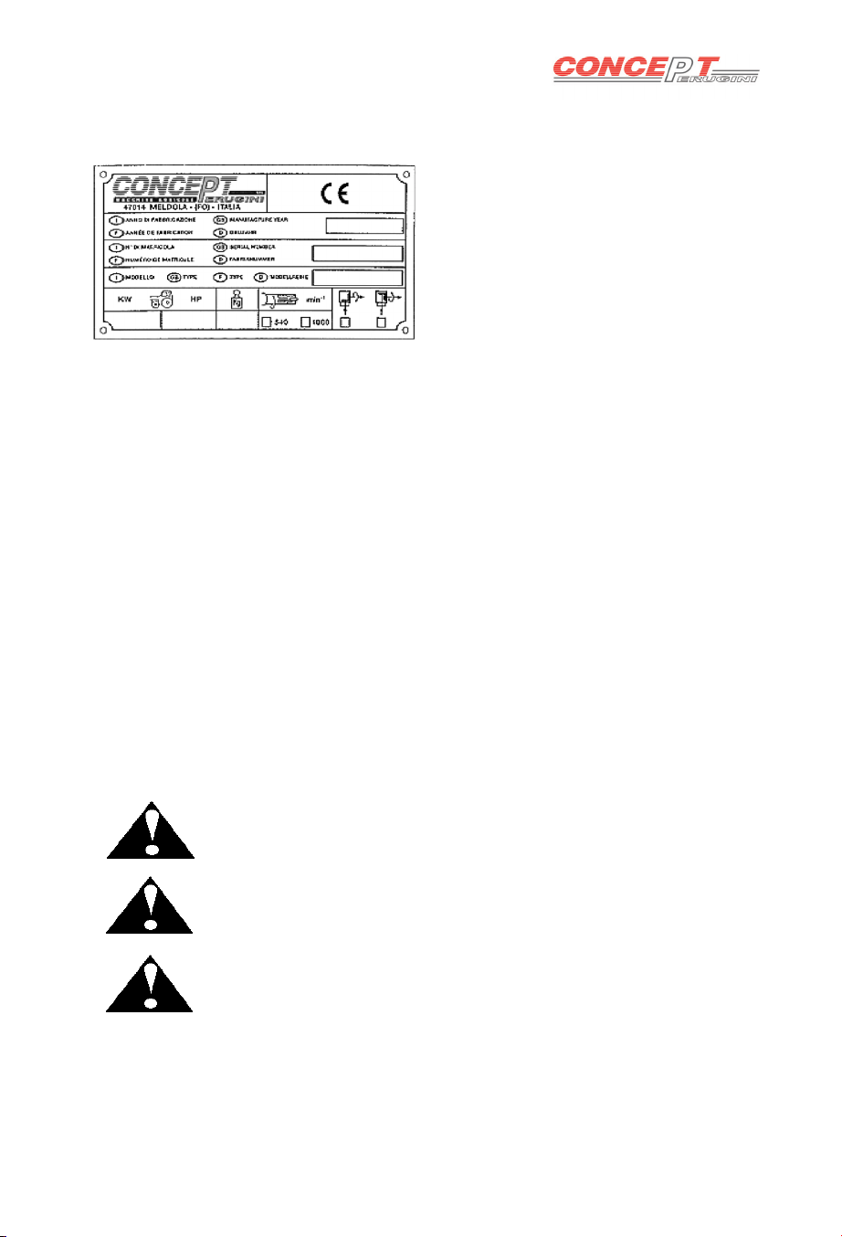
The identication plate, attached to the machine shows the following information:
• Manufacturer’s Name
• CE mark
• Year of production
• Serial number
• Recommended tractor horsepower
• Overall weight
• P.T.O. speed and direction of
rotation
These data are very important in order to check the compatibility between the
machine and the tractor and when ordering spare parts
Before operation
At the factory each machine is carefully inspected to guarantee proper
functioning. In addition, the dealer, before delivering the machine should have
carried out a pre delivery inspection. However as a precaution measure check:
• Oil level in the gearbox
• Grease all those components provided with grease nipples
• Air pressure in the tractor’s tyres, length of lift arms
• Tractor PTO speed to match the machine transmission speed
Safety
Symbols
In this booklet three dierent symbols are used to highlight danger levels or
important information
DANGER
To draw the operator’s attention to situations which could
endanger his or other people safety.
CAUTION
To draw the operator’s attention to situations which could aect
the machine performances but not his or other people safety.
IMPORTANT
To draw the operator’s attention to situations which do not aect
the machine performances and his or other people safety.
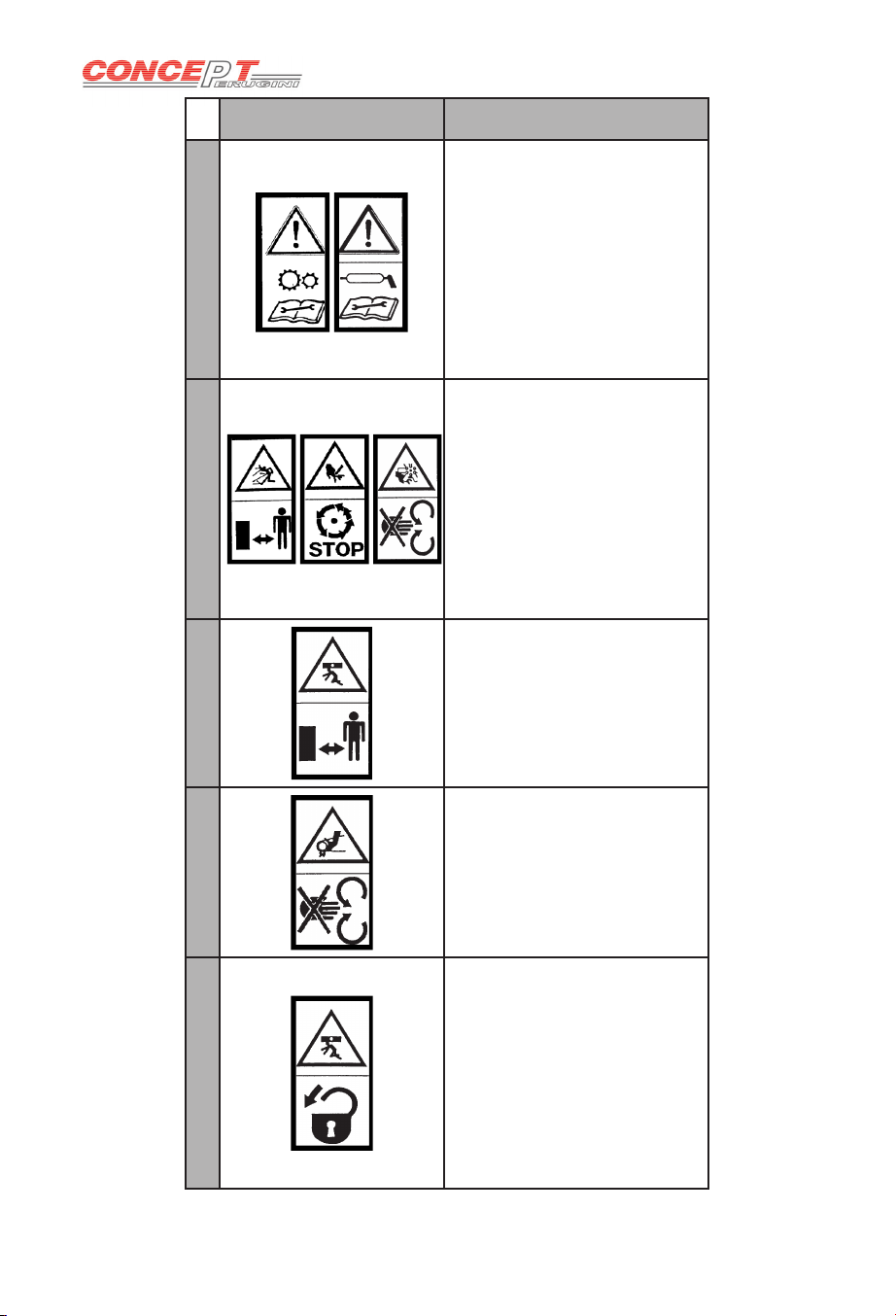
It is important to comply with the instructions given by the safety stickers, which
must always be on the machine. If new ones are required, contact your dealer.

6
SYMBOL DESCRIPTION
1
Before operation, adjusting
or servicing the machine,
it is important that each
operator carefully reads the
following instructions.
Servicing lubrication etc.
should be carried out with
the engine stopped, the
brakes applied and locked
and the starter key removed.
2
Anybody who is near the
machine when working,
must keep at a safe
distance.
During operation keep away
from rotating parts and PTO
shaft. Do not remove safety
guards whilst the machine
is working or with engine
running.
3
Danger of injury to lower
body parts. Anybody who
is near the machine when
working must keep a safe
distance at all times.
4
Danger of injury to limbs.
Anybody who is near moving
parts must be aware of
where his body is in relation
to the machine and keep
at a safe distance. Do not
remove safety guards.
5
Any servicing should be
carried out with the tractor
o and the correct parking
procedures should be
followed out as advised by
the manufacturer. Should
the machine need to be
raised it should be supported
securely.

7
General Safety Instruction
• During operation keep away from rotating parts and PTO shaft, do not
remove safety guards during operation or with the engine running.
• Servicing should be carried out with the engine stopped, the brakes applied
and locked and the started key removed. Once the machine is raised do not
work underneath unless supported securely.
• When travelling on the public road disconnect the PTO shaft and carefully
follow the trac regulations of your country.
• Always lift the machine from the lifting points.
• The operator should be experienced and in good health in order to avoid
injury to his person and others.
• The operator must wear the correct safety garments.
• Do not work when dark unless suitable lighting is available
Operator’s Prerequisites
To avoid danger to himself and others, the operator must be:
• Physically sound
• Mentally sound
• Trained
We advise that the operator read and understand this booklet before using
the machinery. If there are any doubts then contact your dealer or CONCEPT
PERUGINI S.R.L
Work Clothing
The operator must wear the following:
• Working gloves
• Overalls of appropriate size
• Working boots
• Protective glasses
• Protective helmet
When lifting the machine always use the appropriate lifting gear
and always use the lifting points indicated by the yellow and black
stickers as shown in picture.

8
Attaching the machine to the Tractor
Concept Perugini Flail toppers can be linked up to any tractor with a category 1
or 2 three point linkage.
Read the tractor’s instruction manual before attaching attempting to attach the
machine to the tractor.
• Adjust the width of the tractor arms to match the lower brackets on the
machine
• On a at surface reverse the tractor up to the machine
• Firstly attach the lower links and do the necessary adjustments to limit
sideways movement
• Lengthen and attach the top link in order to have the machine parallel to the
ground once attached
• Remember to t all the locking pins and that the machine is safely secured
to the tractor
ALWAYS MAKE SURE THE TRACTOR IS TURNED OFF, P.T.O
IS DISENGAGED AND MACHINE IS MADE SAFE
On the XS ES there is a hitch pin Aon the
headstock that must be removed once attatched
to the tractor. This pin keeps the headstock
locked in a vertical position when the machine is
parked and not linked to a tractor.

9
PTO Shaft
If necessary, cut the PTO shaft to the right length following the shaft
manufacturer instructions.
When attaching the PTO shaft to the machine and tractor make certain that if the
PTO shaft is tted with an overrun clutch this must be installed on the implement.
When connecting to the tractor verify that the locking pin is correctly located and
secure in place. Before use make sure all the chains and guards are correctly
tted.
The height of the machine from the ground is controlled by the rear roller, skids
and top link. Before using the ail mower make sure that the ails do not hit the
ground, this will result in extreme wear and will damage the rotor.
CS have the supports pictured in g.1 to alter the height of the roller simply
slacken bolt A, remove Cand reposition the support in B. Tighten all bolts.
XS model has the supports pictured in g.2. Slacken A remove C, reposition the
support in the desired height (B or C).
ES has the roller brackets shown in g.3. Undo bolts A move the plate to the
desired height and tighten bolts A. Depending on the width of the machine the
plates may be either on the inside of the chassis or the outside.
3
Working Depth
A
A
A
A
1
B
B
C
C
2

10
Hydraulics
The CS XS ES DS SS MS are hydraulic verge mowers following is the table with
all the movement information.
INTERNAL GEARBOX -D EXTERNAL GEARBOX -F

11
INTERNAL GEARBOX -D
MODEL A B C
CS 110 425 1550 1080
CS 135 425 1810 1080
XS-D 125 600 1890 1330
XS-D 140 600 2090 1330
XS-D 155 600 2220 1330
XS-D 165 600 2340 1330
ES-D 140 620 2100 1350
ES-D 160 620 2230 1350
ES-D 180 620 2490 1350
ES-D 200 620 2620 1350
EXTERNAL GEARBOX -F
MODEL A B C
XS-F 125 340 2150 1590
XS-F 140 340 2350 1590
XS-F 155 340 2480 1590
XS-F 165 340 2600 1590
ES-F 140 340 2380 1630
ES-F 160 340 2510 1630
ES-F 180 340 2770 1630
ES-F 200 340 2900 1630

12
To use your verge mower rstly connect the hydraulic hoses to the tractors
double acting spool valve.
Ram Adjustment
When the machine is connected
for the rst time to the tractor
the oil ow must be regulated
to get the desired movement
speed. The machine should
not move to quickly but must
move steadily to avoid hitting
obstacles and damages.
To adjust the oil ow undo the counter nut with a 13mm spanner and adjust the
centre screw with an allen key, tightening the centre screw will reduce oil ow
and loosening it will increase oil ow.
The tap on the machine ram must be opened during use and closed during
transport. This acts as a safety block, restricting oil ow and therefor locking the
implement in its position. During transportation the mower should never be in the
upright position.
N.B The ow restrictors should never be adjusted with the oil under pressure.
This wil lead to personal injury and damage the machinery. Always lift the
machine o the ground before using the hydraulic movements.

13
In the Field
Once the machine has been attached to the tractor, adjusted and inspected then
it can be operated in the eld.
• Lower the machine to approximately 10 cm from the ground.
• Engage the tractor PTO and slowly increase the speed to 540 rpm.
• Lower the machine to the ground, engage a forward moving gear and
commence forward motion.
Alwaysdriveinastraightline,whenturningliftthemachineotheground
to avoid straining the parts in contact with the ground.
Road Transport
When transporting the implement attached to a tractor on public roads ensure
that you comply with the relevant regulations.
• Class of roads permitted for travel may be restricted.
• Transport may be restricted to daylight or o peak trac hours.
• Signs indicating width may be required.
• Lights indicating vehicle width may be required for the hours of darkness.
• Disengage PTO when transporting.
• Ensure all hitch pins are correctly tted with retaining pins.
IF THE MACHINE IS PROVIDED WITH AN OPENING
TAILGATE, THIS CAN BE OPENED ONLY WITH THE
MACHINE STOPPED. FOR NO REASON CAN THE MACHINE
BE USED IN THE FIELD WITH THE TAILGATE OPEN.
NEVER START THE MACHINE WHEN AT 90°
ALWAYS ENGAGE PTO WHEN ROTOR IS PARALLEL TO THE
GROUND

14
Maintenance
The maintenance for the Concept Perugini ail mowers is very straight forward.
Lubrication
Every 10 working hours:
• Grease side shift sliding parts with Agip 33/FD or equivalent
Every 50 working hours:
• Check the gear box and side shaft oil level. If necessary top up with gear oil
EP90
Every 250 working hours or once a year:
• Change the oil in the gear box and the side shaft
• Grease the rear roller bearings. DO NOT OVER-GREASE the bearings, this
will lead to the seal braking causing dirt to enter the bearing and eventually
ceasing it.
To control the oil level in the gearbox use
tap Alocated behind the plastic guard.
The guard must be removed in order to
access tap A.
A
A

15
Rotor
Maintenance on the rotor is very important.
Before and After each use check to see if the rotor and ails are damaged. If
the rotor is damaged it will cause it to become unbalanced creating unwanted
vibrations which will lead to the supports breaking. If the rotor is damaged then
contact your local dealer.
Check the bolts for tightness and the ails for wear and breakages. Replace all
broken,bent or worn blades.
To replace the blades machine must be lifted and the blades replaced from
underneath, make sure the machine is properly supported and made safe.

16
Transmission
The transmission on all Concept Perugini ail
mowers is belt driven. After the rst 2/3 hours of
use check the tension in the belts via the slot on
the belt guard, there should be 5 mm play when
10kgf are applied.
Belt tension observation slot
Should the belts need tensioning or replacing,
the procedure is very simple.
INTERNAL GEARBOX
• Slacken the bolt C
• Slacken the bolts indicated A
• Adjust the tension by either tightening or
slackening bolt B, NB. Loosen the counter
nuts on Bbefore tightening or slackening
• When the belts are taught tighten the
counter nuts on Band tighten Aand C
EXTERNAL GEARBOX
• Slacken the 4 bolts indicated A
• Tighten or loosen bolt Bto reach the
optimum tension. NB loosen counter
nut on Bbefore either tightening or
slackening
• Once the tension has been made
tighten all bolts Band A
C
A
B
A
A
A
B

17
Stone Guards
The front stone guards are very important for the protection of the tractor driver.
Under no circumstances should the machine be used without the front stone
guards. If the guards are bent, worn or broken they should be immediately
replaced, failure to do so can result in severe injury and in certain cases can
cause death.
The picture shows the comparison between a used worn and bent stone guard
(top) and a new guard (bottom).
If the machine is properly set up, set at the correct height and the top tractor link
is adjusted accordingly then the stone guards should be able to hang freely and
not dig into the ground.
ALL MAINTENANCE MUST BE CARRIED OUT WITH THE TRACTOR
ENGINE OFF, P.T.O DISENGAGED AND THE MACHINE PROPERLY
SUPPORTED. FAILURE TO DO SO CAN RESULT IN SERIOUS INJURY
Storage
Before storing the ail mower after it’s seasonal use it is recommended that
a thorough check and clean is carried out. Remove all dirt and address any
severely worn parts or broken parts. Treat any areas of the machine where the
paint has worn o with a rust inhibitor and store in a dry place out of the elements
to insure a longer life span. Grease the P.T.O shaft following the manufacturers
recommendations.
Spare Parts
For the correct spare parts contact your local dealer and ensure that you have
the all of the identication data and correct codes of the parts required.
Always use genuine Concept spare parts
GENUINE PARTS

18
During the warranty period the appropriate maintenance should be carried failure
to do so will breach any cover necessary,
Concept Perugini S.R.L covers warranty with the exemption of wearing parts,
providing that the fault is due to defects in workmanship or material and is in
any way or to any extent not attributable to misuse, lack of reasonable care and
general wear or to the tting of spares, replacements or extra components which
are not supplied or approved by Concept Perugini S.R.L. failure to comply will
void warranty and should any problems a rise Concept Perugini S.R.L is not held
responsible and is not required to answer to any warranty claims.
Warranty
THE USE OF NON GENUINE PARTS WILL NULLIFY THE
WARRANTY
This manual suits for next models
14
Table of contents
Other Concept Perugini Farm Equipment manuals
Popular Farm Equipment manuals by other brands

Nutriculture
Nutriculture Amazon Aeroponic System Assembly and operating instruction

JF
JF 1600-AT S3 instruction manual

Tru-Test
Tru-Test WaterPro 2 user guide

Scheppach
Scheppach DP3000 Original instruction manual

Ziegler
Ziegler PKT 450 Operating instructions and spare parts list

GSi
GSi 40 Series Construction manual