Concept Perugini XT Series User manual

INSTRUCTION BOOK
Manufactured by
CONCEPT PERUGINI S.R.L.
Via Dell’Artigianato, 11-15
47014 Meldola (FC)
Italia
TEL.: +39 0543494602
FAX: +39 0543 494727
www.conceptagri.com
CONCEPT PERUGINI S.R.L. RESERVES THE RIGHT TO MODIFY THEIR
PRODUCTS WITHOUT PRIOR NOTICE AND THE COMMITMENT TO UPDATE
THIS MANUAL
FLAIL MOWERS
CONCEPT PERUGINI

INDEX
Introduction ......................................... 3
Instruction Manual.................................... 4
Identication ........................................ 5
Before operation ..................................... 5
Safety .............................................. 5
Symbols ............................................ 5
General Safety Instruction ............................. 7
Operator’s Prerequisites. . . . . . . . . . . . . . . . . . . . . . . . . . . . . . . 7
Work Clothing ....................................... 7
Attaching the machine to the Tractor .................... 8
PTO Shaft ........................................... 8
Working Depth ....................................... 8
Side Shift ........................................... 9
In the Field ......................................... 10
Road Transport ..................................... 10
Maintenance........................................ 10
CT Belt Adjustment .................................. 12
XT YT Belt Adjustment ............................... 12
Storage ............................................ 13
Spare Parts. . . . . . . . . . . . . . . . . . . . . . . . . . . . . . . . . . . . . . . . . 13
Warranty ........................................... 14

3
Introduction
Concept Perugini S.R.L would like to thank you for purchasing this Flail mower
and oer their support and assistance throughout its productive life.
We strongly recommend that this booklet is read and understood before using
your new machine, and that regular maintenance is carried out as described
further in the booklet. If any doubts arise then don’t hesitate to contact your local
dealer or the company via the options provided on the front page or via Facebook
@ Concept Perugini.
We recommend you take a moment to write down the Serial Number, Year of
Manufacture and Model, as this information will facilitate ordering spare parts.
Serial Number:
Year of Manufacture:
Model:

4
Instruction Manual
The aim of this manual is to help you (the user) understand how to use and how
to maintain the machinery. This booklet covers the following models : CT XT YT
XT
YT
CT

5
Identication
The identication plate, attached to the machine shows the following information:
• Manufacturer’s Name
• CE mark
• Year of production
• Serial number
• Recommended tractor horsepower
• Overall weight
• P.T.O. speed and direction of
rotation
These data are very important in order to check the compatibility between the
machine and the tractor and when ordering spare parts
Before operation
At the factory each machine is carefully inspected to guarantee proper
functioning. In addition, the dealer, before delivering the machine should have
carried out a pre delivery inspection. However as a precaution measure check:
• Oil level in the gearbox
• Grease all those components provided with grease nipples
• Air pressure in the tractor’s tyres, length of lift arms
• Tractor PTO speed to match the machine transmission speed
Safety
Symbols
In this booklet three dierent symbols are used to highlight danger levels or
important information
DANGER
To draw the operator’s attention to situations which could
endanger his or other people safety.
CAUTION
To draw the operator’s attention to situations which could aect
the machine performances but not his or other people safety.
IMPORTANT
To draw the operator’s attention to situations which do not aect
the machine performances and his or other people safety.
It is important to comply with the instructions given by the safety stickers, which
must always be on the machine. If new ones are required, contact your dealer.

6
SYMBOL DESCRIPTION
1
Before operation, adjusting
or servicing the machine,
it is important that each
operator carefully reads the
following instructions.
Servicing lubrication etc.
should be carried out with
the engine stopped, the
brakes applied and locked
and the starter key removed.
2
Anybody who is near the
machine when working,
must keep at a safe
distance.
During operation keep away
from rotating parts and PTO
shaft. Do not remove safety
guards whilst the machine
is working or with engine
running.
3
Danger of injury to lower
body parts. Anybody who
is near the machine when
working must keep a safe
distance at all times.
4
Danger of injury to limbs.
Anybody who is near moving
parts must be aware of
where his body is in relation
to the machine and keep
at a safe distance. Do not
remove safety guards.
5
Any servicing should be
carried out with the tractor
o and the correct parking
procedures should be
followed out as advised by
the manufacturer. Should
the machine need to be
raised it should be supported
securely.

7
General Safety Instruction
• During operation keep away from rotating parts and PTO shaft, do not
remove safety guards during operation or with the engine running.
• Servicing should be carried out with the engine stopped, the brakes applied
and locked and the started key removed. Once the machine is raised do not
work underneath unless supported securely.
• When travelling on the public road disconnect the PTO shaft and carefully
follow the trac regulations of your country.
• Always lift the machine from the lifting points.
• The operator should be experienced and in good health in order to avoid
injury to his person and others.
• The operator must wear the correct safety garments.
• Do not work when dark unless suitable lighting is available
Operator’s Prerequisites
To avoid danger to himself and others, the operator must be:
• Physically sound
• Mentally sound
• Trained
We advise that the operator read and understand this booklet before using
the machinery. If there are any doubts then contact your dealer or CONCEPT
PERUGINI S.R.L
Work Clothing
The operator must wear the following:
• Working gloves
• Overalls of appropriate size
• Working boots
• Protective glasses
• Protective helmet
When lifting the machine always use the appropriate lifting gear
and always use the lifting points indicated by the yellow and black
stickers as shown in picture.

8
Attaching the machine to the Tractor
Concept Perugini Flail toppers can be linked up to any tractor with a category 1
three point linkage.
Read the tractor’s instruction manual before attaching attempting to attach the
machine to the tractor.
• Adjust the width of the tractor arms to match the lower brackets on the
machine
• On a at surface reverse the tractor up to the machine
• Firstly attach the lower links and do the necessary adjustments to limit
sideways movement
• Lengthen and attach the top link in order to have the machine parallel to the
ground once attached
• Remember to t all the locking pins and that the machine is safely secured
to the tractor
ALWAYS MAKE SURE THE TRACTOR IS TURNED OFF, P.T.O
IS DISENGAGED AND MACHINE IS MADE SAFE
PTO Shaft
If necessary, cut the PTO shaft to the right length following the shaft
manufacturer instructions.
When attaching the PTO shaft to the machine and tractor make certain that if the
PTO shaft is tted with an overrun clutch this must be installed on the implement.
When connecting to the tractor verify that the locking pin is correctly located and
secure in place. Before use make sure all the chains and guards are correctly
tted.
The height of the machine from the ground is controlled by the rear roller, skids
and top link. Before using the ail mower make sure that the ails do not hit the
ground, this will result in extreme wear will damage the rotor.
Always adjust the top link to keep the machine parallel to the ground when
adjusting the height of the rear roller.
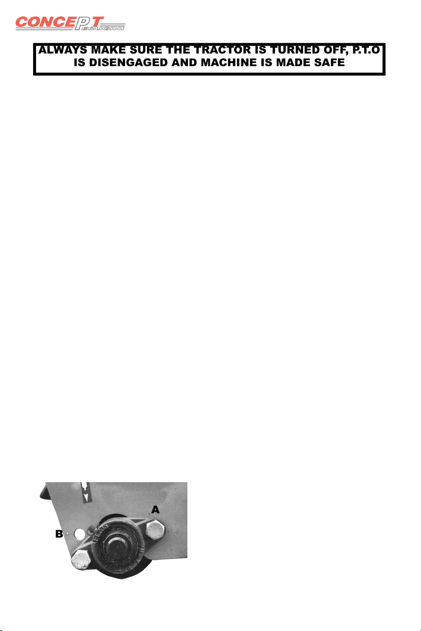
Working Depth
A
B
CT
The working depth is set by altering the
position of the rear roller support.
To do this:
• Slacken bolt A
• Remove and reposition the support in B
• Tighten all bolts
• Repeat for both sides

9
XT YT
The working depth is set by altering the
position of the rear roller supports.
• Slacken A
• Remove Band reposition the support
• Tighten all bolts
• Repeat for both sides
A
B
Side Shift
The YT comes with either mechanical or hydraulic side shift.
To use the hydraulic side shift connect the hoses to the double acting spool valve
on the tractor.
Keep all moving parts well lubricated to minimise wear.
When in the eld always lift the machine o the ground before operating the side
shift, to not do so will strain the machine and will cause breakage.

10
In the Field
Once the machine has been attached to the tractor, adjusted and inspected then
it can be operated in the eld.
• Lower the machine to approximately 10 cm from the ground.
• Engage the tractor PTO and slowly increase the speed to 540 rpm.
• Lower the machine to the ground, engage a forward moving gear and
commence forward motion.
Alwaysdriveinastraightline,whenturningliftthemachineotheground
to avoid straining the parts in contact with the ground.
IF THE MACHINE IS PROVIDED WITH AN OPENING
TAILGATE, THIS CAN BE OPENED ONLY WITH THE
MACHINE STOPPED. FOR NO REASON CAN THE MACHINE
BE USED IN THE FIELD WITH THE TAILGATE OPEN.
Road Transport
When transporting on the road make sure to disconnect the PTO, if the machine
is tted with wheels then fold them in by relocating the pin. Carefully follow the
trac regulations of your country.
Maintenance
The maintenance for the Concept Perugini ail mowers is very straight forward.

11
Lubrication
Every 10 working hours:
Grease the side shift sliding parts with Agip 33/FD or equivalent
Unless there are any leaks then the gearbox oil does not need to be changed or
topped up.
Transmission
The transmission on all Concept Perugini ail
mowers is belt driven. After the rst 2/3 hours of
use check the tension in the belts via the slots
on the belt guard, there should be 5 mm play
when 10kgf are applied.
Belt tension observation slot

12
CT Belt Adjustment
A
• To adjust the belt tension tighten or slacken the bolt A until the desired
tension has been made
• Undo counter bolts B and raise or lower the gearbox in order to make the
side shaft square with the side of the mower
• If the gearbox has been raised or lowered by quite a dierence then the side
shaft guard will need to be moved and made square. To do this slacken bolts
C and move the guard up or down and then tighten C
C
XT YT Belt Adjustment
A
B
C
• Slacken bolts Dwhich are situated inside the
side shaft guard
• Adjust bolt Bas desired in order to obtain the
correct tension
• Via bolts A move the gearbox so that the side
shaft is parallel to the ground and then tighten A
• Slacken C in order to manoeuvre the side shaft
guard so that this too is parallel with the ground,
then tighten Dand C
D
B
B

13
Stone Guards
The front stone guards are very important for
the protection of the tractor driver. Under no
circumstances should the machine be used without
the front stone guards. If the guards are bent, worn
or broken they should be immediately replaced,
failure to do so can result in severe injury and in
certain cases can cause death.
The picture shows the comparison between a used
worn and bent stone guard (top) and a new guard
(bottom).
If the machine is properly set up, set at the correct
height and the top tractor link is adjusted accordingly
then the stone guards should be able to hang freely
and not dig into the ground.
ALL MAINTENANCE MUST BE CARRIED OUT WITH THE TRACTOR
OFF, P.T.O DISENGAGED AND THE MACHINE PROPERLY
SUPPORTED. FAILURE TO DO SO CAN RESULT IN SERIOUS INJURY
Storage
Before storing the ail mower after it’s seasonal use it is recommended that
a thorough check and clean is carried out. Remove all dirt and address any
severely worn parts or broken parts. Treat any areas of the machine where the
paint has worn o with a rust inhibitor and store in a dry place out of the elements
to insure a longer life span. Grease the P.T.O shaft following the manufacturers
recommendations.
Spare Parts
For the correct spare parts contact your local dealer and ensure that you have
the all of the identication data and correct codes of the parts required.
Always use genuine Concept spare parts

14
GENUINE PARTS
THE USE OF NON GENUINE SPARE PARTS WILL NULLIFY THE WARRANTY
Warranty
During the warranty period the appropriate maintenance should be carried failure
to do so will breach any cover necessary,
Concept Perugini S.R.L covers warranty with the exemption of wearing parts,
providing that the fault is due to defects in workmanship or material and is in
any way or to any extent not attributable to misuse, lack of reasonable care and
general wear or to the tting of spares, replacements or extra components which
are not supplied or approved by Concept Perugini S.R.L. failure to comply will
void warranty and should any problems a rise Concept Perugini S.R.L is not held
responsible and is not required to answer to any warranty claims.

15
This manual suits for next models
12
Table of contents
Other Concept Perugini Farm Equipment manuals