Conceptronic CUPS1200 User manual

Multi Language Quick Guide
UPS
CUPS1200,CUPS2200
V1.0

English
Conceptronic CUPS1200,CUPS2200
1. Package contents
The following items are present in the package of the Conceptronic UPS:
•UPS
•Input Schuko power cable
•Output power cable (IEC-IEC)
•USB cable
•Multi language quick installation guide
2. Product overview
FRONT PANEL
Display
When LCD starts to work, it will display
all information for 3 seconds.
When in normal mode, it will display
as below.

English
When in AVR mode, it will display as
below. And the mark will flicker
every 1 second.
When in battery mode, it will display
as below. And the mark will
flicker every 1second.
Note: If I/P-V<40V,input voltage
will display “000”
When in off charging mode, it will
display as below.
Note: the output voltage always is
displayed as “000” in off charging mode.
When in fault mode, it will display as
below. “FAULT” character and “0”
character only.
Load level definition
Load level
Load bar Indication
0%~25%
25%~50%
50%~75%
75%~100%

English
Battery capacity definition
Battery Level
Battery bar Indication
Battery mode
Other mode
Battery voltage<22V
Battery voltage<25.4V
22V≤battery
voltage<23V
25.4V≤battery voltage<26.4V
23V≤battery
voltage<25V
26.4V≤battery voltage<27V
Battery voltage≥25V
Battery voltage≥27V
When over load, the mark will flicker every 1second.
When battery low, the mark will flicker every 1second.

English
REAR PANEL
CUPS1200 CUPS2200
AC input
6*IEC outlet
USB port
RJ45 LAN/Modem/phone line protection
❺Breaker

English
3. Installation & usage
Installation and Initial Startup
Before installation, please inspect the unit. Be sure that nothing is damaged.
I: Placement & Storage Conditions
Install the UPS in a protected area that is free of excessive dust and has
adequate air flow around the unit, and is free from excessive dust, corrosive
fumes and conductive contaminants. Please place the UPS away from other
units at least 20 cm to avoid interference. Do NOT operate the UPS where the
temperature exceeds 0-40°C and the humidity is over 0-90 % RH.

English
II: Connect to Utility and Charge
Plug in the AC input cord to the 2-pole, 3-wire grounded wall outlet. For the best
results, we suggest charging the battery at least 6 hours with no load (no
electrical devices such as computers, monitors, rtc.) connected before initial use.
The unit charges its battery while connecting to the utility.
III: Connect the Loads
Plug in the loads to output receptacles on the rear panel of the UPS. Simply turn
on the power switch of UPS unit, and devices connected to the UPS will be
protected by UPS unit.
Do not attach a power strip or surge suppressor to the UPS.
EN

English
IV: Connect LAN cable, Modem or Phone line for Surge Protection
Connect for example a single modem or phone line into surge-protected “IN”
outlet on the back panel of the UPS unit. Connect from “OUT” outlet to the
computer with another phone line cable.
V: Connect USB Cable
To monitor the UPS status, such as unattended UPS shutdown and start-up, by
using bundled software, please connect the UPS and PC with USB cable included.

English
VI: Turn On/Off the Unit
Turn on the UPS unit by pressing the power switch. Turn off the UPS unit by
pressing again the power switch.
Functions & Operation
I: DC Start Function
DC Start Function enables UPS to be started up when AC utility power is not
available and battery is fully charged. Just simply press the power switch to turn on
the UPS.
NEVER connect a laser printer or scanner to the UPS unit,
because in-rush current generated by motor’s devices may cause
the damage of the unit.

English
II: Green Power Function
These series are equipped with Green Power Function for saving power and
protecting battery. The feature of deep discharge protection is adoped on battery
mode. If no load is connected to the UPS, it will automatically shut down after 5
minutes for energy saving while running on battery mode. The UPS will restart
while AC recovery.
III: AVR (Automatic Voltage Regulation)
If the quality of the incoming mains is poor, the AVR boosts a low incoming voltage
or reduces a high one. The load receives a voltage within the normal range.
IV: Auto restart while AC recovery
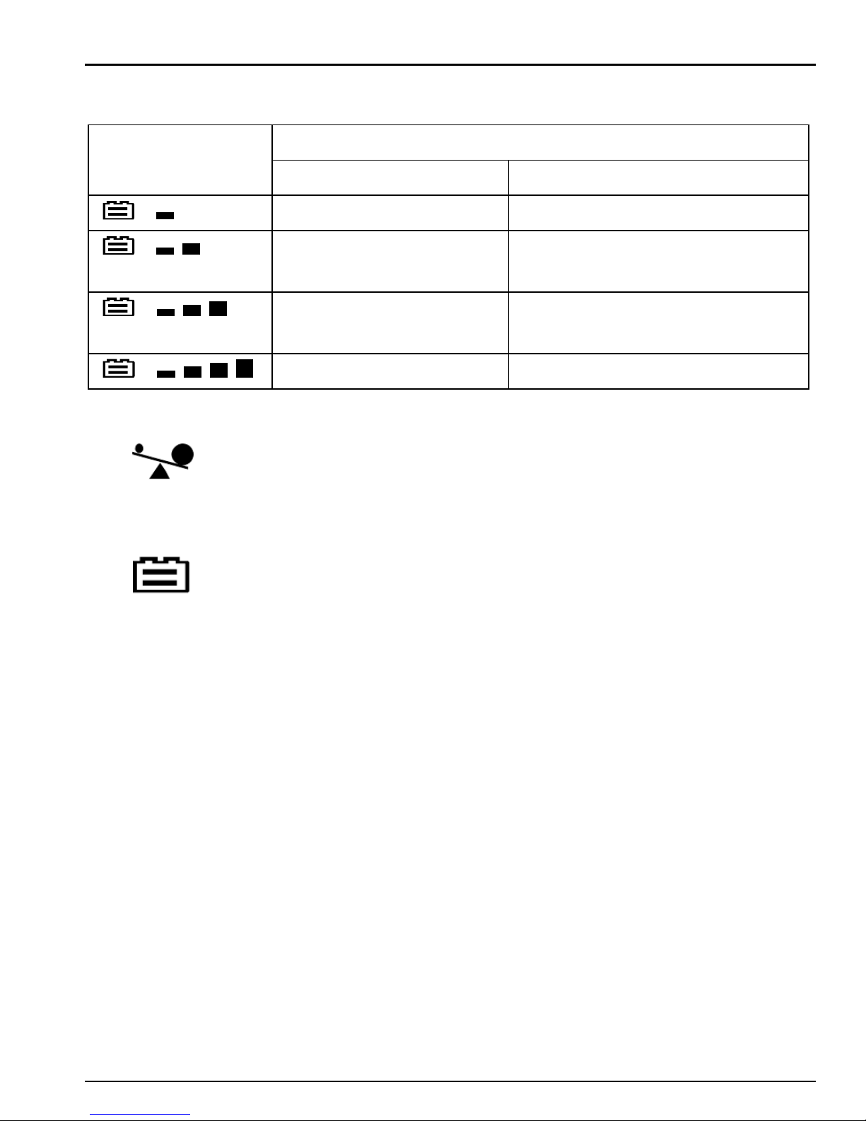
V: Audio Indicator
Audible Alarm
Situation
Sounding every 10 seconds
Battery Mode
Sounding every 1 second
Battery Low
Sounding every 0.5 seconds
Overload
continuous sounding
Faulty
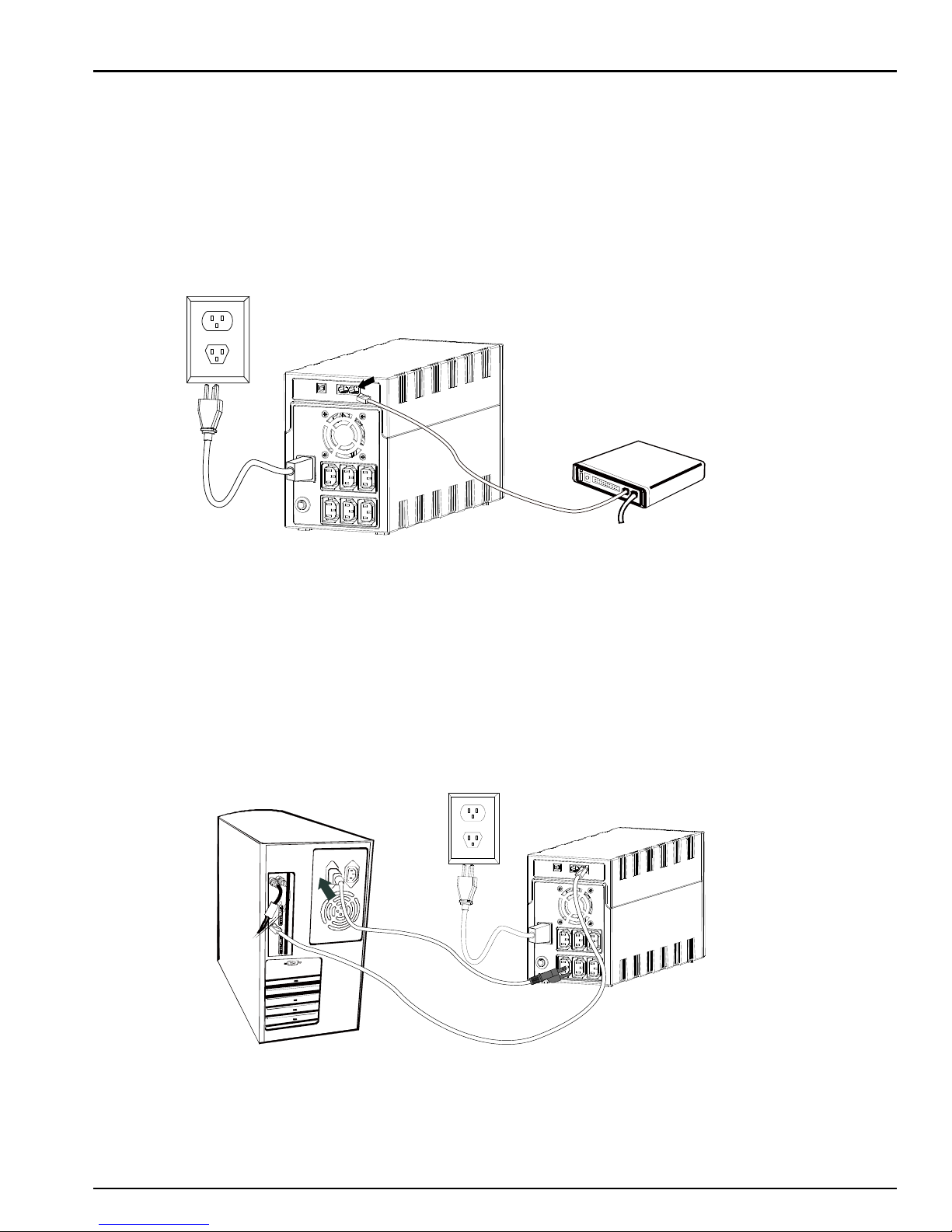
Software Installation on your PC
Connected by USB to a PC or notebook, the Software enables communication
between the UPS and the computer. The UPS software monitors the status of the
UPS, shuts down the system before the UPS is exhausted and can remotely
observe the UPS via the Network (enabling users to manage their system more
effectively). Upon AC failure or UPS battery low, UPS takes all necessary actions
without intervention from the system administrator. In addition to automatic file
saving and system shut-down functions, it can also send warning messages via
pager, e-mail etc.

English
Enter the following serial No. to install software: 511C1-01220-0100-478DF2A
After the software is successfully installed, the communication with UPS has
been established and a green icon will appear in the system tray.
Double-click the icon to use the monitor software (as above).
You can schedule UPS shutdown/start-up and monitor UPS status through PC.
Detail instructions please refer to the e-manual in the software.
Maintenance
I. General
The UPS is virtually maintenance free: take care of proper environmental
conditions and keep air inlets-outlets free of dust.
II. Fuses
If the AC input fuse is defect, be sure it is replaced by a compatible fuse from the
same make and type.
Never short circuit batteries. When working with batteries, remove watches, rings
and other metal objects, and only use insulated tools.
III. Batteries
When replacing the batteries, use batteries with exactly same specifications.
Read all safety rules before replacing the battery.
Check “DDC WEBSITE”from time to time to get the latest version of
monitoring software.

English
TROUBLE SHOOTING
Symptom
Possible Cause
Remedy
No LED display on
the front panel.
1. Battery weak.
1. Charge battery up to 8 hours.
2. Battery defect.
2. Replace with the same type of
battery.
3. Power switch is not pressed.
3. Press the power switch again.
Alarm buzzer beeps
continuously when
AC supply is normal.
Overload of the UPS.
Verify that the load matches the UPS
capability specified in the spec.
When power failure,
back-up time is
shorten.
1. Overload of the UPS.
1. Remove some noncritical load.
2. Battery voltage is too low.
2. Charge battery 8 hours or more.
3. Battery defect due to high
temperature operation
environment, or improper
operation to battery.
3. Replace with the same type of
battery.
Mains normal but
LED is flashing.
Power cord is loose.
Reconnect the power cord properly.
If any abnormal situations occur that are not listed above, please call service people immediately.
Enjoy the use of your Conceptronic UPS!

Deutsch
Conceptronic CUPS1200,CUPS2200
1. Packungsinhalt
Folgende Teile befinden sich in der Verpackung von Conceptronic
UPS:
•UPS
•Input Schuko power cable
•Output power cable (IEC-IEC)
•USB cable
•Multi language quick installation guide
2. Gerätekomponenten
Frontblende
Display
Wenn das LCD zu arbeiten beginnt, zeigt
es alle Informationen 3 Sekunden lang
an.
Im Normalmodus zeigt es wie
nachstehend dargestellt.

Deutsch
Im AVR-Modus erscheint die
nachstehend dargestellte Anzeige.
Zudem blinkt das Symbol alle 1
Sekunde.
Im Akkumodus erscheint die
nachstehend dargestellte Anzeige.
Zudem blinkt das Symbol alle
1 Sekunde.
Hinweis: Bei I/P - V < 40 V zeigt die
Eingangsspannung „000“
Im abgeschalteten Lademodus erscheint
die nachstehend dargestellte Anzeige.
Hinweis: Die Ausgangsspannung wird im
abgeschalteten Lademodus immer mit
„000“ angezeigt.
Im Fehlermodus erscheint die
nachstehend dargestellte Anzeige.
Nur „Fehler“- und „0“-Zeichen.
Laststufendefinition
Laststufe
Lastleistenindikation
0%~25%
25%~50%
50%~75%
75%~100%

Deutsch
Akkukapazitätsdefinition
Akkustand
Akkuleistenindikation
Akkumodus
Anderer Modus
Akkuspannung < 22 V
Akkuspannung < 25,4 V
22 V ≤ Akkuspannung
< 23 V
25,4 V ≤ Akkuspannung <
26,4 V
23 V ≤ Akkuspannung
< 25 V
26,4 V ≤ Akkuspannung < 27
V
Akkuspannung ≥ 25V
Akkuspannung ≥ 27 V
Bei Ü berlastung blinkt das Symbol alle 1 Sekunde.
Bei geringen Akkustand blinkt das Symbol alle 1 Sekunde.

Deutsch
Rückblende
CUPS1200 CUPS2200
Netzeingang
6 * IEC-Ausgang
USB-Port
RJ45-LAN-/Modem-/Telefonleitungsschutz
❺Trennschalter

Deutsch
3. Installation & Verwendung
Installation and Initial Startup
Before installation, please inspect the unit. Be sure that nothing is damaged.
I: Placement & Storage Conditions
Install the UPS in a protected area that is free of excessive dust and has
adequate air flow around the unit, and is free from excessive dust,
corrosive fumes and conductive contaminants. Please place the UPS away
from other units at least 20 cm to avoid interference. Do NOT operate the
UPS where the temperature exceeds 0-40°C and the humidity is over 0-90
% RH.

Deutsch
II: Connect to Utility and Charge
Plug in the AC input cord to the 2-pole, 3-wire grounded wall outlet. For the
best results, we suggest charging the battery at least 6 hours with no load (no
electrical devices such as computers, monitors, rtc.) connected before initial
use. The unit charges its battery while connecting to the utility.
III: Connect the Loads
Plug in the loads to output receptacles on the rear panel of the UPS. Simply
turn on the power switch of UPS unit, and devices connected to the UPS will
be protected by UPS unit.
Do not attach a power strip or surge suppressor to the UPS.
EN

Deutsch
IV: Connect LAN cable, Modem or Phone line for Surge Protection
Connect for example a single modem or phone line into surge-protected “IN”
outlet on the back panel of the UPS unit. Connect from “OUT” outlet to the
computer with another phone line cable.
V: Connect USB Cable
To monitor the UPS status, such as unattended UPS shutdown and start-up, by
using bundled software, please connect the UPS and PC with USB cable
included.

Deutsch
VI: Turn On/Off the Unit
Turn on the UPS unit by pressing the power switch. Turn off the UPS unit by
pressing again the power switch.
Functions & Operation
I: DC Start Function
DC Start Function enables UPS to be started up when AC utility power is not
available and battery is fully charged. Just simply press the power switch to
turn on the UPS.
II: Green Power Function
NEVER connect a laser printer or scanner to the UPS unit,
because in-rush current generated by motor’s devices may cause
the damage of the unit.
This manual suits for next models
1
Table of contents
Languages:
Other Conceptronic UPS manuals

Conceptronic
Conceptronic CUPS650 User manual

Conceptronic
Conceptronic ZEUS 05E User manual

Conceptronic
Conceptronic CUPS650 User manual

Conceptronic
Conceptronic ZEUS03EP User manual

Conceptronic
Conceptronic CUPS650US User manual

Conceptronic
Conceptronic ZEUS02ES User manual

Conceptronic
Conceptronic CUPS600 User manual

Conceptronic
Conceptronic ZEUS 01E User manual