Concoa IntelliSwitch 57 Series Technical specifications

ADI 9506
Medical
IntelliSwitch
Electronic
Switchover
MAINTENANCE INSTRUCTIONS
Carefully Read These Instructions Before Performing Any Maintenance
Carefully Read These
Controls Corporation of America
1501 Harpers Road • Virginia Beach, VA 23454
Telephone 1-800-225-0473 or 757-422-8330 • Fax 757-422-3125
www.concoa.com January 2008
Preliminary
TM

2
CAUTION!
Persons performing installation,
maintenance and repairs to a medical gas
pipeline system must adhere to NFPA-99
requirements in the design, installation,
testing, operation and maintenance
of their piped gas system.
This includes the incorporation of
CONCOA's Medical IntelliSwitch.
Adhering to the CONCOA’s ADI does not
constitute full compliance to NFPA-99
requirements - Refer to NFPA-99 for
complete requirements.
This manual is not intended to replace or
provide complete details of NFPA-99.

3
USER RESPONSIBILITY
Service to this product should only be performed by CONCOA or an authorized CONCOA agent. Requests for service may be made
through CONCOA CUSTOMER SERVICE at 1-800-225-0473. Written requests may be made using CONCOA’s FAX number at 1-
757-422-3125 or CONCOA’s E-MAIL at info@concoa.com
CONCOA accepts no responsibility for damage or injury if this product is modified in any way. CONCOA assumes/accepts no
liability or responsibility for damage to individuals or equipment that may occur when using this product.
SAFETY
THIS PRODUCT IS NOT INTENDED FOR USE WITH TOXIC GASES, FLAMMABLE GASES OR CORROSIVE GASES.
NOTICE
The Medical IntelliSwitch™ is intended for use in medical installations. This product meets NFPA-99
requirements for switchover systems. Compliance with NFPA-99 for a complete installation (ie Cylinders, piping,
alarms, etc.) are the responsibility of the installer. Refer to NFPA-99 for complete system requirements.
Basic safety precautions must be followed to reduce the risk of fire, electrical shock or injury.
•Connect the Medical IntelliSwitch™ to the correct line voltage. A label on the product identifies what voltage it is wired for.
CONNECTION TO AN INCORRECT VOLTAGE CAN CAUSE SERIOUS DAMAGE TO THE PRODUCT AND WILL
VOID ANY WARRANTY.
•While the Medical IntelliSwitch™ Switchover is dust and moisture resistant, it is NOT water-proof or completely sealed. It
should be installed where it will not be subjected to rain or high concentrations of dust. Never pour or spray liquids directly
onto the product.
•Install the Medical IntelliSwitch™ where the ambient temperature range is between 0° F and 140° F.
•Do not install this product in a hazardous environment.
•If product appears damaged in any way, do not use and request service from CONCOA.
•Consult the cylinder distributor for the proper use of cylinders and for any restrictions on their use (such as flow rate and
temperature requirements).
•Store cylinders with valve caps screwed on, and chain cylinders to a supporting wall or column.
•Handle cylinders carefully and only with valve caps screwed on. The cap will reduce the chance that the cylinder valve will
break off if the cylinder is accidentally dropped or falls over. The cap also protects the cylinder valve from damage to screw
threads, which could cause leaky connections.
•No smoking should be permitted near oxygen, nitrous oxide, any other oxidizer, flammable gases, or flammable mixtures, or
in areas where cylinders are stored.
•Where an oxidizer (such as nitrous oxide or oxygen) is used, the manifold and cylinders must be kept clean. No oil, grease, or
combustible substances should come in contact with oxygen or nitrous oxide storage or handling equipment. Such materials
in contact with oxygen or nitrous oxide are readily ignitable and, when ignited, will burn intensely.
•Never lift gas cylinders with a magnetic lifting device.
•Never use an open flame when leak testing.
•Always open valves slowly when high-pressure gases are being used.
•Always be sure that a cylinder contains the correct gas before connecting it to any manifold.
•Always leak-test any manifold or distribution pipeline before using.
•Always be sure that the gas in a pipeline is the correct gas for the intended use.
•Always close all cylinder valves before disconnecting cylinders from a manifold.
•Always remove all empty cylinders from a manifold before connecting full cylinders.
•Always test cylinders to be sure the cylinders are full before connecting to a manifold.

4
DESCRIPTION OF PRODUCT
The Medical IntelliSwitch™ is a device used to monitor, control and switch the flow of gas from cryogenic or high pressure cylinders
from either of two independent sources to either of two independently controlled and isolated delivery regulators. In turn these
regulators are connected to a single point of use output.
It consists of two electronically controlled inlet valves controlling the flow of gas into two electronically controlled valves that in turn
direct the flow of gas into one of two delivery regulators.
Pressure coming into the Medical IntelliSwitch™ is monitored and displayed on two independent 4-digit displays. The outlet pressure
of the system is monitored and displayed on a 3-digit display. Outlet pressure adjustment is available using an adjusting screw on the
delivery regulators inside the cabinet.
A series of indicator lights show the status of the system at any given time.
The status of the Medical IntelliSwitch™ may be monitored remotely via a serial port or optional Ethernet port. In addition, the
Medical IntelliSwitch™ can interface with a CONCOA Remote Alarm.
OPERATING THE MEDICAL INTELLISWITCH™
For a detailed explanation on the proper operation of the Medical IntelliSwitch™, refer to the CONCOA instruction manual ADI
9504.
IN-SERVICE REPAIR VS REPAIR CLASSIFICATION
Some repairs and adjustments can be made to the Medical IntelliSwitch™ while it is delivering gas to downstream users – these are
refered to as in-service repairs. Others require that the Medical IntelliSwitch™ be turned off in order to perform the necessary repairs.
Throughout this manual, each section will indicate either ‘IN-SERVICE REPAIR’ or ‘REPAIR’
CAUTION: When a REPAIR is needed and the unit must be turned off to complete the necessary repairs, actions must be taken to be
able to provide gas to the downstream users.

5
Figure 1

6
IN-SERVICE ADJUSTMENTS
Resetting Inlet Regulator Pressure---------------------------------------------------------------------------------------------------------------Page 9
Resetting Delivery Regulator Pressure -------------------------------------------------------------------------------------------------------- Page 10
Performing Self Test----------------------------------------------------------------------------------------------------------------------------- Page 14
IN-SERVICE REPAIR PARTS
DELIVERY REGULATORS FOR N2O AND CO2 SERVICE:
8056763-41 ------Regulator, 55 psi delivery pressure (with Chloroprene Seat) --------------------------------------------------------- Page 33
8056767-41 ------Regulator, 100 psi delivery pressure (with Chloroprene Seat)-------------------------------------------------------- Page 33
8056769-41 ------Regulator, 180 psi delivery pressure (with Chloroprene Seat)-------------------------------------------------------- Page 33
DELIVERY REGULATORS FOR OXYGEN, HELIUM, AND NITROGEN SERVICE:
8056762-41 ------Regulator, 55 psi delivery pressure (with Viton® Seat) --------------------------------------------------------------- Page 33
8056766-41 ------Regulator, 100 psi delivery pressure (with Viton® Seat)-------------------------------------------------------------- Page 33
8056768-41 ------Regulator, 180 psi delivery pressure (with Viton® Seat)-------------------------------------------------------------- Page 33
ALARM WIRING CONNECTOR AND CABLE ASSEMBLIES:
8309170-17 ------Wiring connector for Alarm plug in bottom of the Medical IntelliSwitch® ---------------------------------------- Page 12
5295316-3--------Alarm Connector Cable Assembly, 6pin x 6pin, 3ft long
5295316-10 ------Alarm Connector Cable Assembly, 6pin x 6pin, 10ft long
5295316-25 ------Alarm Connector Cable Assembly, 6pin x 6pin, 25ft long
5295316-50 ------Alarm Connector Cable Assembly, 6pin x 6pin, 50ft long
5295316-100-----Alarm Connector Cable Assembly, 6pin x 6pin, 100ft long
SERIAL PORT WIRING CONNECTOR AND CABLE ASSEMBLY:
5295321 ----------Serial Connector Cable Assembly, 9pin x D9(female), 10ft long
GASKETS:
8350234 ----------Gasket, Inside Door - Note: Each unit requires 2 door gaskets, 570 Series
8350235 ----------Gasket, Inside Door - Note: Each unit requires 2 door gaskets, 571 Series
WIRE ROUTING COMPONENTS:
8309240-27 ------Clip, Self Adhesive Cable Routing, 1/2" Square
8309240-28 ------Clip, Self Adhesive Cable Routing, 3/4" Square
8309240-23 ------Clip, Self Adhesive Cable Routing, 1" Square
8309240-4--------Tie Wrap for 1/2" Square Clip
8309240-30 ------Tie Wrap for 3/4" Square Clip
8309240-29 ------Tie Wrap for 1" Square Clip

7
REPAIR ADJUSTMENTS
Resetting Switchover Pressure ----------------------------------------------------------------------------------------------------------------- Page 19
Resetting Delivery Regulator Pressure Tolerance ------------------------------------------------------------------------------------------- Page 21
Resetting Units of Measure --------------------------------------------------------------------------------------------------------------------- Page 22
Resetting Keypad Security Lockout ----------------------------------------------------------------------------------------------------------- Page 23
Resetting Remote Alarm Outputs-------------------------------------------------------------------------------------------------------------- Page 24
Enabling Remote Setup-------------------------------------------------------------------------------------------------------------------------- Page 26
Changing AC Input Power---------------------------------------------------------------------------------------------------------------------- Page 27
Setting Communication Mode------------------------------------------------------------------------------------------------------------------ Page 29
REPAIR PARTS (REPAIR)
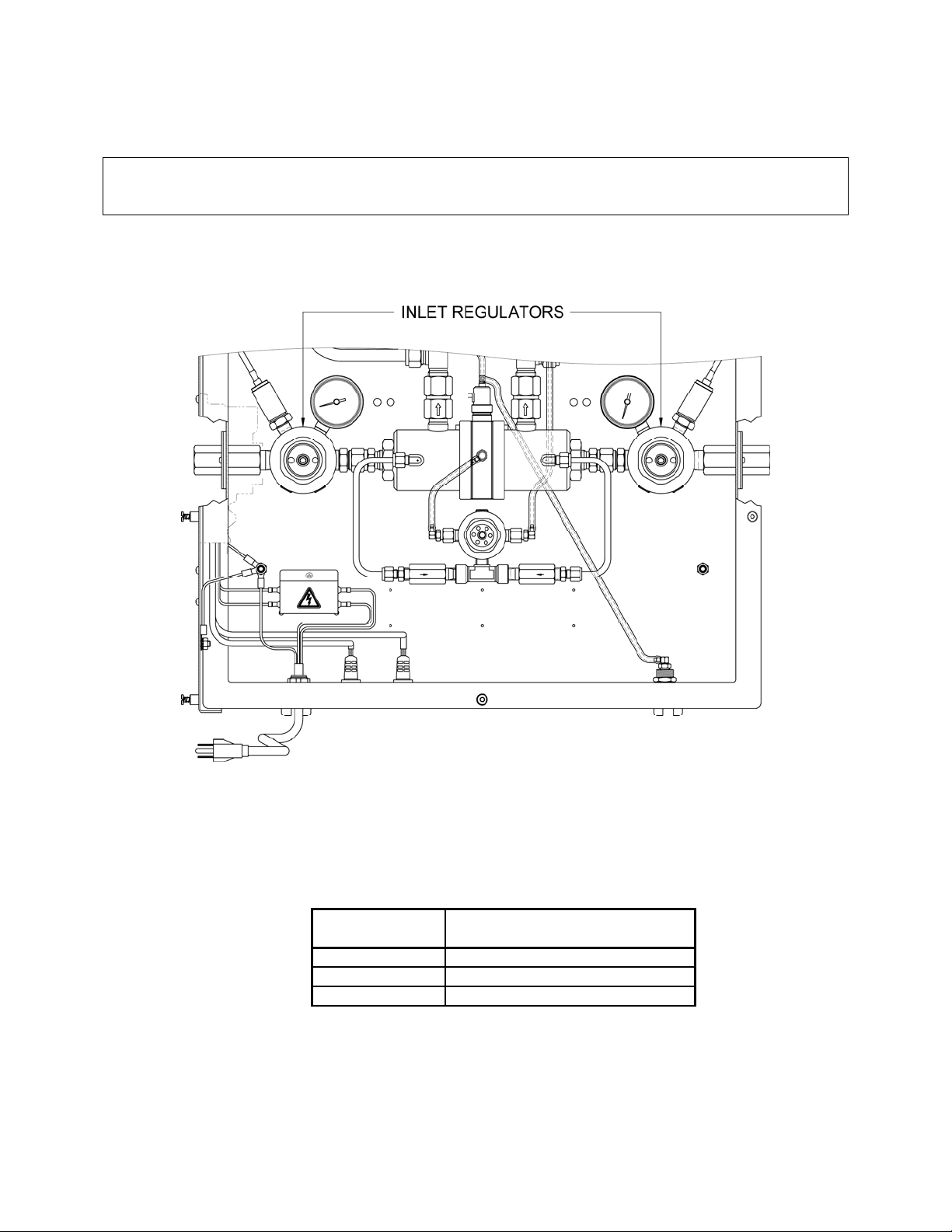
INLET REGULATORS FOR N2O AND CO2 SERVICE:
8056761-41 ------Regulator, for 55 psi delivery pressure units (with Chloroprene Seat)----------------------------------------------- Page 31
8056765-41 ------Regulator, for 100 psi and 180 psi delivery pressure units (with Chloroprene Seat)------------------------------- Page 31
INLET REGULATORS FOR OXYGEN, HELIUM, AND NITROGEN SERVICE:
8056760-41 ------Regulator, for 55 psi delivery pressure units (with Viton® Seat) ---------------------------------------------------- Page 31
8056764-41 ------Regulator, for 100 psi and 180 psi delivery pressure units (with Viton® Seat) ------------------------------------ Page 31
INTERNAL CABLE ASSEMBLIES:--------------------------------------------------------------------------------------------------------- Page 37
8355031 ----------Power Cord Assembly ----------------------------------------------------------------------------------------------------- Page 39
8355028 ----------Remote Alarm--------------------------------------------------------------------------------------------------------------- Page 41
8355027 ----------Serial Port-------------------------------------------------------------------------------------------------------------------- Page 42
8355030 ----------Power Cable (between fuse block and circuit board) ------------------------------------------------------------------ Page 43
8355032 ----------Ground Strap ---------------------------------------------------------------------------------------------------------------- Page 44
8355024 ----------Left Inlet Pressure Transducer, 570 series Medical IntelliSwitch®-------------------------------------------------- Page 45
8355025 ----------Right Inlet Pressure Transducer, 570 series Medical IntelliSwitch® ------------------------------------------------ Page 45
8355026 ----------Delivery Pressure Transducer, 570 series Medical IntelliSwitch®--------------------------------------------------- Page 45
8355034 ----------Left Inlet Pressure Transducer, 571 series Medical IntelliSwitch®-------------------------------------------------- Page 45
8355035 ----------Right Inlet Pressure Transducer, 571 series Medical IntelliSwitch® ------------------------------------------------ Page 45
8355036 ----------Delivery Pressure Transducer, 571 series Medical IntelliSwitch®--------------------------------------------------- Page 45
8309140-11 ------Solenoid Valves------------------------------------------------------------------------------------------------------------- Page 46
8355022 ----------Solenoid Valve Connector Cable, Delivery Regulator Valve (upper), 570 Series Only--------------------------- Page 47
8355023 ----------Solenoid Valve Connector Cable, Switch Valve (lower)-------------------------------------------------------------- Page 47
CIRCUIT BOARDS:
8355005 ----------Control Board, 570 series Medical IntelliSwitch®-------------------------------------------------------- Contact CONCOA
8355029 ----------Display Board, 570 series Medical IntelliSwitch® ------------------------------------------------------- Contact CONCOA
8355003 ----------Control Board, 571 series Medical IntelliSwitch® ------------------------------------------------------- Contact CONCOA
8355009 ----------Display Board, 571 series Medical IntelliSwitch® ------------------------------------------------------- Contact CONCOA
FUSE COMPONENTS:
8309200-2--------Fuse – Note: Each unit requires 2 fuses --------------------------------------------------------------------------------- Page 28
8309200-12 ------Fuse Holder
8309245-12 ------Screws for Fuse Holder - Note: Each unit requires 2
8309828 ----------Fuse Cover Plate
8309245-12 ------Screw for Cover Plate
8307270 ----------Label, Electrical Warning Symbol

8
REPAIR PARTS (REPAIR) - Continued
ASSORTED COMPONENTS:
8309765-7--------Gasket, Solenoid Vent Bulkhead
8309765-2--------Gasket, Anti-Spin Plate - Note: Each unit requires 4
8350008 ----------Anti-Spin Plate - Note: Each unit requires 4
8309245-20 ------Screws, Anti-Spin Plate – Note: Each unit requires 8
8309170-47 ------Port Cap for Serial and Alarm Ports on bottom of unit – Note: Each unit requires 2
8350019 ----------Outlet and Relief Valve Bulkheads – Note: Each unit requires 2
835XXX----------Inlet Bulkhead / Inlet Filter Assemblies – Note: Each unit requires 2
8350094 ----------Relief Valve for 55 psi delivery pressure
8350095 ----------Relief Valve for 100 and 180 psi delivery pressure models
8305369 ----------Check Valve for N2O and CO2, 1/4", Pilot Regulator – Note: Each unit requires 2
8305383 ----------Check Valve for O2, He and N2, 1/4", Pilot Regulator – Note: Each unit requires 2
5500205 ----------Gauge, Inlet Regulator Dial
90800022---------Tubing, Red
8350282 ----------Grips, Yellow Plastic for 1/4-turn valves
8306619 ----------Tube Fitting, 1/2 NPT male x 1/2 Tube, 90° Elbow, for Delivery Regulators
5802041 ----------Relief Valve, Prior to Delivery Regulators
8350006 ----------Magnet
8350007 ----------Hex Key
8350280 ----------Label, Regulator Status
8350281 ----------Label, Valve Status
835XXXX--------Door Tether
8309246-27 ------Nut, KEPS for Door Tether – Note: Each unit requires 2
8355032 ----------Ground Strap
8309246-27 ------Nut, KEPS for Ground Strap – Note: Each unit requires 2

9
RESETTING INLET REGULATOR PRESSURE (IN-SERVICE)
The Inlet Regulator Pressure is factory set based on the model purchased. If it is necessary to change the pressure of the regulators
after installation perform the following steps:
CAUTION:
Adjustment of the inlet regulators could result in reduced flow performance and malfunction of the reserve inlet
(optional) for the Medical IntelliSwitch.
1. Open door by loosening the four screws holding it to the cabinet.
2. Locate the Allen wrench attached to the inside panel.
Figure 2
3. Starting with the inlet regulator that is currently in use, place the Allen wrench into the set screw and adjust the pressure to
the desired value. The delivery pressure of the inlet regulator can be seen on the internal pressure gauges. Turning the set
screw clockwise increases pressure. Counterclockwise decreases pressure. The system will not decrease in pressure if there
is no flow. See Figure 2 for the location of the regulators.
Default Factory Settings:
Model Number
I
n
l
e
t
R
egu
l
a
t
or
S
e
t
P
o
i
n
t
(while flowing gas)
57X2XXX 155-160 PSIG
57X3XXX 240-250 PSIG
57X7XXX 240-250 PSIG
4. After setting the first inlet regulator, press the bank select button on the front panel to switch to the other bank. Repeat step 3
to set the second inlet regulator. For best performance, both inlet regulators should be set to the same pressure.

10
RESETTING DELIVERY REGULATOR PRESSURE (IN-SERVICE)
The Delivery Regulator Pressure is factory set based on the model purchased. If it is necessary to change the pressure of the
regulators after installation perform the following steps:
CAUTION: Adjustment of the delivery regulators should be performed while the Medical IntelliSwitch is flowing gas. Adjustment in
a static condition (not flowing) will effect the available pressure during max flow conditions.
1. Open door by loosening the four screws holding it to the cabinet.
2. Using Figure 3, locate DIP switch SW4 at the bottom of the electronic circuit board on the door. Move SW4-4 to the
ON position. The front panel display will show a screen similar to Figure 4 indicating the system is in CALIBRATE
mode. The front panel display will show the inlet pressure from the side that it is currently drawing from.
Figure 3
3. Locate the Allen wrench attached to the inside panel.
4. There is a green light to the left or right of the delivery display that indicates which delivery regulator is in use. If the
left light is ON, the pressure being displayed in the delivery display is the output pressure of the left regulator. Similarly,
if the right green light is ON the pressure being displayed is from the right regulator.
5. Locate the Allen wrench attached to the inside panel. Starting with the delivery regulator that is currently in use, place
the Allen wrench into the set screw and adjust the pressure to the desired value. Turning the set screw clockwise
increases pressure. Counterclockwise decreases pressure. The system will not decrease in pressure if there is no flow.
See Figure 5 for the location of the regulators.
Default Factory Settings:
Model Number
D
e
li
very
R
egu
l
a
t
or
S
e
t
P
o
i
n
t
(while flowing gas)
57X2XXX 54-57 PSIG
57X3XXX 98-102 PSIG
57X7XXX 178-182 PSIG
6. After the pressure is set to the desired value, press the Output Source Pushbutton on the front panel to switch to the other
delivery regulator.
7. Place the Allen wrench into the set screw of the second regulator and adjust the pressure to the desired value.

11
Figure 4
It is possible to switch back to the other delivery regulator and change its pressure by pushing the Output Source PB again.
The delivery pressure for both regulators should be the same to within 1-2 PSI for best performance.
8. When the desired delivery pressure for both regulators is set, turn OFF SW4-4 on the control board. See Figure 4.
9. Locate SW5 on the control board (Figure 3) and press it once. The system should go back to normal operation showing
inlet pressures on both inlet displays.
10. Calibration is complete. Close door and re-attach screws.
Figure 5

12
CONNECTING TO A REMOTE ALARM (IN-SERVICE)
The Medical IntelliSwitch™ is capable of interfacing to CONCOA’s Advantium Rx Remote Alarm. The 6-pin remote alarm interface
connector is located at the bottom of the Medical IntelliSwitch™ cabinet (See Figure 1). There are two ways to connect the product to
an alarm. Ready made cable assemblies for connecting the Medical IntelliSwitch™ to an Advantium Rx Alarm are available from the
factory. Contact your local CONCOA Distributor or call 1-800-225-0473 for information. The other option is to build your own
cable assembly to connect the two devices. For convenience, a mating 6-pin connector is provided to use in building this cable
assembly. The Advantium Rx Alarm comes with a mating connector that is used to attach to the remote alarm side of the cable
assembly. The recommended cable for this assembly is 22 AWG, 6-conductor stranded wire (Alpha # 1176C or equivalent). The
length of this cable should be limited to 1500 feet.
Cut the 6-conductor cable to length. Remove the outer jacket of the cable to expose approximately 3/4 inch of the internal conductors
on both sides of the cable. Strip away 1/4-inch of the insulation on each of the conductors.
On the 6-pin connector, slide the protective cover, cable retainer, and locking nut over the end of the cable as shown in Figure 6.
Figure 6
Figure 7

13
Using the pin assignments shown in Table 1 and the connector views in Figure 6 and Figure 7, solder the wires to the appropriate pins.
After soldering is complete, slide the locking nut over the connector body. Snap the cable retainer into the body and then slide the
protective cover over the cable retainer.
Table 1— Remote Alarm Pin Assignments
Medical IntelliSwitch™
Pin Number
529-5136 Alarm
Pin Number Function
1 1 Left Inlet Alarm
2 2 Delivery Regulator Alarm.
3 3 +12v (provided by the remote alarm)
4 4 Right Inlet Alarm Status
5 5 Auxiliary Gas Supply Alarm.
6 6 Ground (provided by the remote alarm)
Wire terminations to the Alarm side of the cable are done in the same fashion as the Medical IntelliSwitch™ connector.
Slide the protective cover, cable retainer, and locking nut over the end of the cable as shown in Figure 6.
Figure 8
Using the pin assignments shown in Table 1 and the connector views in Figure 6 and Figure 8, solder the wires to the
appropriate pins. After soldering is complete, slide the locking nut over the connector body. Snap the cable retainer into
the body and then slide the protective cover over the cable retainer.

14
PERFORMING SELF TEST (IN-SERVICE)
Through the use of the Reset button on the front panel, a number of items can be observed or analyzed. A number 1 - 21 which is
displayed on the output pressure display identifies each test. To enter Test Mode press and hold the Reset button for 4 seconds. The
system will beep 3 times and then enter Test Mode. A description of the tests follows.
Test 1 –Display Test
This test exercises all segments of the displays and all status
lights except the power and remote alarm indication. If serial
communication is selected, the system will output a code
indicating that a self-test is being performed.
Test 2 - Date of Manufacturing
This test shows the year, month and day the product was
manufactured
Test 3 - Software Revision
This is the revision of the software running the product.
Test 4 – Analog Channel Check
This checks the circuitry that is used to read the pressure
transducers. It should display a value between 475 to 525 to
be working properly.
Test 5 - Display Switchover Pressure
The number on the display is the switchover (changeover)
pressure value that is internally set for product operation. The
value is in the units of measure selected for the product (PSI,
BAR, etc.)

15
Test 6 – Auxiliary Settings
Displays settings for Units of Measure, Communication
setting, Keypad lockout, allow remote settings enable,
Auxiliary Gas source enable.
Refer to Table 9 to determine what is enabled
Test 7 – Delivery Regulator Pressure Tolerance
This number represents the value added or subtracted to the
nominal delivery pressure of the product. It is used to
determine the allowable range of operation before a delivery
regulator fault condition is declared.
Test 8 – Look Back Time
This value is the number of minutes the system waits before
looking back.
Test 9 – Switch Back Time
This is the value, in minutes, used by the system to determine
when a cylinder is truly empty and incapable of supplying
sufficient gas.
Test 10 – Hysteresis
This is a pressure value used to prevent the system from
inadvertently switching back and forth between inlet sides
unnecessarily.

16
Test 11 – Offset Values
These numbers (factory set) are used to calibrate the left and
right inlet pressures.
Test 12 – Calibration Values
These numbers are used to calibrate the inlet channels at zero
PSI.
Test 13 – Test Left Inlet Valve
This test turns ON the left inlet valve allowing gas to flow
from that side while turning OFF the right inlet valve.
Test 14 – Test Right Inlet Valve
This test turns ON the right inlet valve allowing gas to flow
from that side while turning OFF the left inlet valve.
Test 15 – Test Left Delivery Regulator
This test turns ON the left delivery regulator while turning
OFF the right delivery regulator.

17
Test 16 – Test Right Delivery Regulator
This test turns ON the right delivery regulator while turning
OFF the left delivery regulator.
Test 17 – Test Left Inlet Alarm
This test activates the left inlet alarm relay contact.
Test 18 – Test Right Inlet Alarm
This test activates the right inlet alarm relay contact.
Test 19 – Test Regulator Alarm
This test activates the delivery regulator alarm relay contact.
Test 20 – Test Reserve Gas Supply Alarm
This test activates the reserve gas supply alarm relay contact.

18
Test 21 – Keypad test
This test allows the testing of each function button on the front
control panel and also indicates the status of the two toggle
switches used to indicate the presence of the delivery
regulators.
When a button is pressed, a segment will light on one of the
displays.
Table 2 (for Test 6)
Display Value.
Allow Remote
Keypad Lockout
MPA
BAR
PSI
Auxiliary
Ethernet
RS485
RS232
Display Value
Allow Remote
Keypad Lockout
MPA
BAR
PSI
Auxiliary
Ethernet
RS485
RS232
1 OFF OFF OFF OFF ON OFF OFF OFF ON 129 ON OFF OFF OFF ON OFF OFF OFF ON
2 OFF OFF OFF OFF ON OFF OFF ON OFF 130 ON OFF OFF OFF ON OFF OFF ON OFF
4 OFF OFF OFF OFF ON OFF ON OFF OFF 132 ON OFF OFF OFF ON OFF ON OFF OFF
8 OFF OFF OFF OFF ON ON OFF OFF OFF 136 ON OFF OFF OFF ON ON OFF OFF OFF
17 OFF OFF OFF ON OFF OFF OFF OFF ON 145 ON OFF OFF ON OFF
OFF OFF OFF ON
18 OFF OFF OFF ON OFF OFF OFF ON OFF 146 ON OFF OFF ON OFF
OFF OFF ON OFF
20 OFF OFF OFF ON OFF OFF ON OFF OFF 148 ON OFF OFF ON OFF
OFF ON OFF OFF
24 OFF OFF OFF ON OFF ON OFF OFF OFF 152 ON OFF OFF ON OFF ON OFF OFF OFF
33 OFF OFF ON OFF OFF OFF OFF OFF ON 161 ON OFF ON OFF OFF OFF OFF OFF ON
34 OFF OFF ON OFF OFF OFF OFF ON OFF 162 ON OFF ON OFF OFF OFF OFF ON OFF
36 OFF OFF ON OFF OFF OFF ON OFF OFF 164 ON OFF ON OFF OFF OFF ON OFF OFF
40 OFF OFF ON OFF OFF ON OFF OFF OFF 168 ON OFF ON OFF OFF ON OFF OFF OFF
65 OFF ON OFF OFF ON OFF OFF OFF ON 193 ON ON OFF OFF ON OFF OFF OFF ON
66 OFF ON OFF OFF ON OFF OFF ON OFF 194 ON ON OFF OFF ON OFF OFF ON OFF
68 OFF ON OFF OFF ON OFF ON OFF OFF 196 ON ON OFF OFF ON OFF ON OFF OFF
72 OFF ON OFF OFF ON ON OFF OFF OFF 200 ON ON OFF OFF ON ON OFF OFF OFF
81 OFF ON OFF ON OFF OFF OFF OFF ON 209 ON ON OFF ON OFF OFF OFF OFF ON
82 OFF ON OFF ON OFF OFF OFF ON OFF 210 ON ON OFF ON OFF OFF OFF ON OFF
84 OFF ON OFF ON OFF OFF ON OFF OFF 212 ON ON OFF ON OFF OFF ON OFF OFF
88 OFF ON OFF ON OFF ON OFF OFF OFF 216 ON ON OFF ON OFF ON OFF OFF OFF
97 OFF ON ON OFF OFF OFF OFF OFF ON 225 ON ON ON OFF OFF
OFF OFF OFF ON
98 OFF ON ON OFF OFF OFF OFF ON OFF 226 ON ON ON OFF OFF
OFF OFF ON OFF
100 OFF ON ON OFF OFF OFF ON OFF OFF 228 ON ON ON OFF OFF
OFF ON OFF OFF
104 OFF ON ON OFF OFF ON OFF OFF OFF 232 ON ON ON OFF OFF ON OFF OFF OFF

19
RESETTING SWITCHOVER PRESSURE (REPAIR)
The Medical IntelliSwitch™ can be configured to switch at pressures ranging from 100 to 500 PSI. This value is factory set but can be
changed in the field. Each system has a specific switchover pressure set at the factory based on the delivery pressure ordered. To
change the switchover pressure from the factory set value, perform the following steps:
Default Factory Settings:
Model Number
S
witchover Pressure
57X2XXX 155 PSIG
57X3XXX 240 PSIG
57X7XXX 240 PSIG
1. Turn power OFF to the system.
2. Open door by loosening the four screws holding it to the cabinet.
3. Using Figure 9, locate DIP switch SW1 at the bottom of the electronic circuit board on the door.
Figure 9
4. Using Table 3 or Table 4, set the desired switchover pressure.
5. Close system door and tighten 4 screws holding door to cabinet.
6. Turn power back ON. The new switchover pressure will take effect on power ON.
Table 3 — DIP Switch Settings
SWITCH VALUE
SW1-1 1
SW1-2 2
SW1-3 4
SW1-4 8
SW1-5 16
SW1-6 32
SW1-7 64
SW1-8 128
SW1-9 256
Note:
The values shown in the table are
additive. Example: To set switchover
pressure to 130 PSI, turn on SW1-8
(128) and SW1-2 (2). These added
together equal 130 PSI.

20
Note: Tables 3 & 4 show values in PSI. If operating in BAR or MPA it will be necessary to convert the PSI units to the units
being used in order to use the tables. To convert values to BAR divide the PSI value by 14.5. To convert the values to
MPA divide the Phe PSI value by 145.
Table 4 — Typical Switchover Pressure DIP Switch Settings
PSI SW1-1 SW1-2 SW1-3 SW1-4 SW1-5 SW1-6 SW1-7 SW1-8 SW1-9
75 ON ON
OFF ON OFF OFF ON OFF OFF
100 OFF OFF ON OFF OFF ON ON
OFF OFF
125 ON OFF ON ON ON ON ON
OFF OFF
135 ON ON ON
OFF OFF OFF OFF ON OFF
150 OFF ON ON
OFF ON OFF OFF ON OFF
175 ON ON ON ON
OFF ON OFF ON OFF
200 OFF OFF OFF ON OFF OFF ON ON
OFF
225 ON OFF OFF OFF OFF ON ON ON
OFF
250 OFF ON OFF ON ON ON ON ON
OFF
275 ON ON
OFF OFF ON OFF OFF OFF ON
300 OFF OFF ON ON
OFF ON OFF OFF ON
325 ON OFF ON OFF OFF OFF ON OFF ON
350 OFF ON ON ON ON
OFF ON OFF ON
375 ON ON ON
OFF ON ON ON
OFF ON
400 OFF OFF OFF OFF ON OFF OFF ON ON
425 ON OFF OFF ON OFF ON OFF ON ON
450 OFF ON OFF OFF OFF OFF ON ON ON
475 ON ON
OFF ON ON
OFF ON ON ON
500 OFF OFF ON OFF ON ON ON ON ON
Table of contents
Other Concoa Medical Equipment manuals